Warranty
Warranty malfunctions occurring under conditions of normal use in
conformity with the Instruction Manual and Product Precautionary
Markings will be repaired free of charge. This warranty is valid for a
period of one (1) year from the date of purchase. Please contact the
distributor from which you purchased the product for further informa-
tion on warranty provisions.
Introduction
Thank you for purchasing the HIOKI 9290-10 CLAMP ON ADAPTER.
To obtain maximum performance from the product, please read this
manual first, and keep it handy for future reference.
Overview
The Model 9290-10 is a clamp-on adapter rated for 1500A AC, with a
10:1 CT ratio.
In addition to the larger clamping capability, broad frequency character-
istics and good phase characteristics reliably provide clamp-on Power
HiTesters with expanded range and large current measurements.
Initial Inspection
When you receive the product, inspect it carefully to ensure that no
damage occurred during shipping. If damage is evident, or if it fails to
operate according to the specifications, contact your dealer or Hioki
representative.
Maintenance and Service
• To clean the product, wipe it gently with a soft cloth moistened with
water or mild detergent. Never use solvents such as benzene, alco-
hol, acetone, ether, ketones, thinners or gasoline, as they can
deform and discolor the case.
• If the product seems to be malfunctioning, contact your dealer or
Hioki representative. Pack the product carefully so that it will not be
damaged during shipment, and include a detailed written description
of the problem. Hioki cannot be responsible for damage that occurs
during shipment.
Follow these precautions to ensure safe operation and to obtain the
full benefits of the various functions.
Safety Symbol
The following symbols in this manual indicate the relative
of cautions and warnings.
Indicates that incorrect operation presents an
that could result in serious injury or death to the user.
Indicates that incorrect operation presents a significa
ard that could result in serious injury or death to the user.
Indicates that incorrect operation presents a possib
injury to the user or damage to the product.
Advisory items related to performance or correct operation
the product.
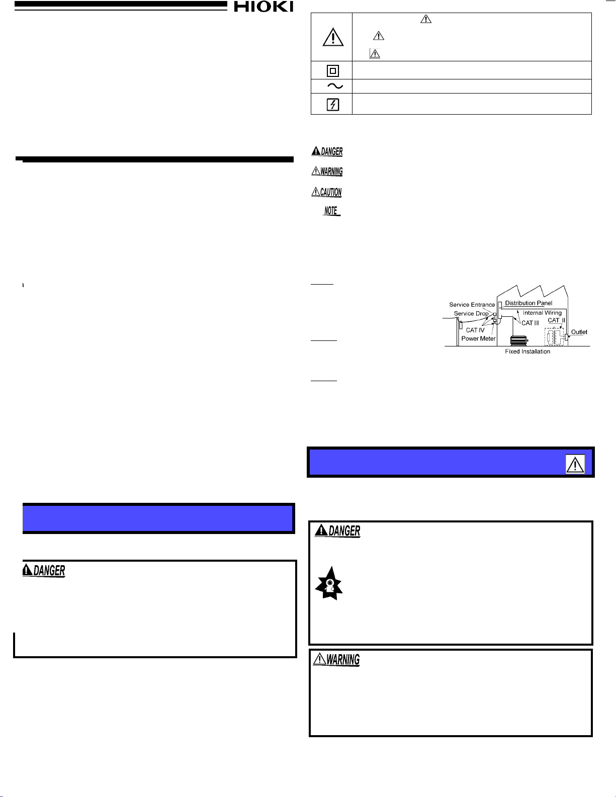
Measurement categories
This product complies with CAT III safety requirements.To ensure safe
tion of measurement products, IEC 61010 establishes safety standards f
ious electrical environments, categorized as CAT II to CAT IV, and
measurement categories.
CAT II: Primary electrical circuits in
equipment connected to an AC
electrical outlet by a power cord
(portable tools, household appli-
ances, etc.)
CAT II covers directly measuring
electrical outlet receptacles.
CAT III: Primary electrical circuits
of heavy equipment (fixed installa-
tions) connected directly to the dis-
tribution panel, and feeders from
the distribution panel to outlets.
CAT IV: The circuit from the service drop to the service entrance, an
power meter and primary overcurrent protection device (distribution panel).
Using a measurement product in an environment designated with
numbered category than that for which the product is rated could result
severe accident, and must be carefully avoided.
Use of a measurement instrument that is not CAT-rated in CAT II to CAT
measurement applications could result in a severe accident, a
fully avoided.
This manual contains information and warnings essential for
operation of the product and for maintaining it in safe operating
tion. Before using the product, be sure to carefully read the
safety notes.
Accurate measurement may be impossible in the presence of strong magnetic
fields, such as near transformers and high-current conductors, or in the pres-
ence of strong electromagnetic fields such as near radio transmitters.
Preliminary Checks
Before using the product the first time, verify that it operates normally
to ensure that the no damage occurred during storage or shipping. If
you find any damage, contact your dealer or Hioki representative.
rdg.:reading value (The value currently being measured and indicated on the
measuring product)
The clamp sensor and secondary coil are marked to indicate the direc-
tion of current flow, to ensure that the measurement current and out-
put current have the same phase.
Attach the clamp around only one conductor. Single-phase (2-wire) or
three-phase (3-wire) cables clamped together will not produce any reading.
The effect of conductor positioning of the clamp sensor clamped to the
secondary coil should be considered. Please verify the specifications
of the clamp sensor being used.
Safety
This product is designed to conform to IEC 61010 Safety Stan-
dards, and has been thoroughly tested for safety prior to ship-
ment. However, mishandling during use could result in injury or
death, as well as damage to the product. Be certain that you
understand the instructions and precautions in the manual
before use. We disclaim any responsibility for accidents or inju-
ries not resulting directly from product defects.
9290-10
CLAMP ON ADAPTER
Instruction Manual
September 2013 Revised edition 5 Printed in Japan
9290B980-05 13-09H
In the manual, the symbol indicates particularly import
mation that the user should read before using the product.
The symbol printed on the product indicates that the user
should refer to a corresponding topic in the manual (marke
the symbol) before using the relevant function.
Indicates a double-insulated device.
Indicates AC (Alternating Current).
Indicates that the instrument may be connected to
from a live circuit.
Usage Notes
• To avoid short circuits and potent
hazards, never attach the product to a circuit that
ates at more than the 600V.
• This product should only be connected to the
ondary side of a breaker, so the breaker can
an accident if a short circuit occurs
should never be made to the primary sid
breaker, because unrestricted current flow
cause a serious accident if a short circuit occur
• To avoid electric shock, do not touch the
beyond the protective barrier during use.
• To avoid electric shock, do not allow the product to ge
and do not use it when your hands are wet.
• To avoid electric shock when measuring live lin
appropriate protective gear, such as insulated rubber
boots and a safety helmet.
• Note that the product may be damaged if curre
the selected measurement range is applied for a long time.
• Do not store or use the product where it could be exposed to direct
sunlight, high temperature or humidity, or condensation. Under
such conditions, the product may be damaged and insulation may
deteriorate so that it no longer meets specifications.
• Be careful to avoid dropping the product or otherwise subjecting
them to mechanical shock, which could damage the mating surfac-
es of the core and adversely affect measurement.
• Keep the clamp jaws and core slits free from foreign objects, which
could interfere with clamping action.
• Keep the clamp closed when not in use, to avoid accumulating dust
or dirt on the mating core surfaces, which could interfere with clamp
performance.
• Avoid stepping on or pinching the cable, which could damage the
cable insulation.
• To avoid damaging the cables, do not bend or pull the cables.
Before using the product, make sure that the insulation on the
cables is undamaged and that no bare conductors are improp-
erly exposed. Using the product in such conditions could cause
an electric shock, so contact your dealer or Hioki representative
for repair.
Specifications
Rated primary current 1500 A AC
CT ratio 10 : 1
Operating tempera-
ture and humidity for
guaranteed accuracy
Period of guaranteed
accuracy
23±5
°C (73
±
41°F)
, 80%RH or less (non-condensating)
1 year
Amplitude accuracy
±
1.5% rdg. (at 45 - 66 Hz)
Amplitude frequency
characteristics Within ±2% rdg. at 20 Hz - 5 kHz (deviation from accu-
racy)
Phase accuracy Within ±1.0
°
(at 45 - 66 Hz)
Phase frequency
characteristics Within ±1.0
°
at 20 Hz - 5 kHz (deviation from accuracy)
Effect of conductor
position Within ±1.5% (deviation from center)
Effect of external
electromagnetic field 1 A equivalent or less
(in an AC electromagnetic field of 400 A/m)
Maximum input current1000 A continuous, 1500 A AC (5 minutes)
Temperature coeffi-
cient 0.02%rdg./
°C
OperatingTemperature
&Humidity 0 to 50
°C (32 - 122°F)
, 80%RH or less
(non-condensating)
Storage Temperature
&Humidity -10 to 60
°C (14 - 140°F)
, 80%RH or less
(non-condensating)
Operating EnvironmentIndoors, <2000 m (6562-ft.) ASL
Dielectric strength 5312 V AC rms for 15 seconds (between case and
core)
Maximum rated volt-
age to earth 600 V AC rms or less
Standards applying Safety
EN61010
Type A current sensor
Measurement Category III, Pollution Degree
2
(Anticipated Transient Overvoltage: 6000 V)
Measurable conductor
diameter 55 mm (2.17”) or less
80 X 20 mm, Buss bars
Secondary coil inside
diameter Approx. 27 mm X 27 mm (1.06” X 1.06”)
Cable length Approx. 3 m (118.11”)
Size Approx. 99.5W X 188H X 42D mm
(3.92”WX7.40”HX1.65”D)
(excluding protrusions)
Weight Approx. 580 g (20.5 oz.)
Accessory Instruction Manual (1), Mark band (6, 3 sets)
Parts Names
Measurement Procedures
Lever
Clamp jaws
Cable
Barrier
Secondary coil
OK
1. Open the clamp sensor,
align the current direction
indicator arrow toward the
load side, and clamp around
one conductor.
2. Make sure the clamp sensor
jaws are firmly closed.
Clamp the smaller clamp
sensor through the opening
of the secondary coil.
3. In this case, be sure to align
the current direction indica-
tor arrow on the secondary
coil with the indicator on the
clamp sensor.
4. Remember that the actual
current in the circuit being
measured is ten times that
indicated by the measuring
instrument.
9290-10 9290-10
9660
9290-10
3127-10
9661
Example of Combining Clamp Sensors or Clamp Meters
Position the clamp with the current direc-
tion indicator pointing toward the load side.
(If installed in the opposite direction,the
phase deviates 180 degrees.)
LOAD
SOURCE
Clamp the conductor.
Electric
conductor
indicator
Current direction
www.GlobalTestSupply.com
Find Quality Products Online at: sales@GlobalTestSupply.com