Dillon AFG Series User manual

1
Thank you for choosing the Dillon Advanced Force
Gauge (AFG) or Advanced Force/Torque Indicator
(AFTI II) instrument. With correct use and regular
recalibration it will give many years of accurate and
reliable service.
The Dillon AFG is the latest in a series of highly
adaptable display units. By using the latest inte-
grated circuit technology it has been possible to
produce a truly universal display which can be used
to measure force, torque or weight when com-
bined with suitable transducers.
Upon receiving the unit please check for obvious
physical damage to the packaging material and the
instrument itself. If any damage is evident please
notify your Dillon distributor immediately.
We strongly recommend you keep all packaging for
future shipping requirements.
The most commonly used features such as force or
torque display, peak detection and the changing of
displayed units, can all be done with just one key
press per function on the front panel.
Operation
Introduction

2
As shown in Figure 1, the control panel has eight
keys.
Figure 1
AFG front panel
To power up the unit, press the green ON key. A
short self test runs during which the display will
show the software version number, revision date
and the instrument’s capacity in newtons.
After the self test and providing no load has been
applied to the instrument the display will show all
zeroes. This is because the unit rezeroes itself
during the self-test routine.
Please note that an
instrument with an
integral transducer
(AFG) measuring very
low forces may not
show zero if it is
moved during the self
test routine. Once the
unit is properly
mounted and zeroed
the reading will be
stable.
Powering Up
the Unit
The Nicad battery in
the AFG has been
charged prior to
delivery but for
maximum battery life
we recommend that
you charge the
battery for at least
20 hours before
operating.
You can use the AFG
while it is charging.

3
The instrument is now in the display mode. This is
the most commonly used mode. The display is
showing the actual force that is being applied to the
unit.
If a force is carefully applied via the sensing probe
(hole at bottom of AFG, only) the reading on the
display will register this applied force.
Do not overload the transducer as this will cause
irreparable damage. In this display mode, forces or
torques greater than 120% of full scale will produce
a constant sound warning coupled with an OL
symbol on the display. The instrument keeps a
record of all overloads that are applied. This can
only be cleared by trained Dillon staff or represen-
tatives.
Tensile forces on the AFG are displayed as positive
numbers and compressive forces as negative
numbers, the minus sign appearing to the left of the
digits when shown. See Figure 2.
Figure 2
Display of tension and compression
Display of
Tension/
Compression

4
The display also has symbols located at the left
which directly relate to this sign (two triangular
arrows pointing away from each other for tension
and two triangular arrows pointing toward each
other for compression).
The display is equipped with rotating arrow
symbols which will appear when the unit is config-
ured for torque. See Figure 3. Clockwise torques
are displayed as positive numbers and counter-
clockwise torques as negative numbers. The
arrows directly relate to the sign just like the
tension and compression symbols described above.
Figure 3
Torque display
During the operation of the unit it is often neces-
sary to zero the display. Do this by pressing the
ZERO key. When the instrument is actually
zeroing itself, the top and bottom row of display
segments will alternately blink once. The display
should then read all zeroes. See Figure 4.
Display of
Torque
Zeroing
the AFG

5
You can choose among the following units of
measure: pounds, ounces, Newtons, kilograms, and
grams.
On torque based instruments you can choose from
kilogram.centimeters, pound.feet, pound.inches and
Newton.meters. The actual units available will vary
depending on the range of the instrument. The
most suitable set of units is automatically selected
within the instrument’s operating program accord-
ing to its range and type.
To change the display units press the UNITS key.
The newly selected units will be shown at the
bottom of the display, as shown in Figure 5. Each
successive key press will select the next available
units until the instrument returns to the original.
Figure 5
Changing unit of measure
Changing Unit
of Measure
Figure 4
Zeroing the AFG

6
The instrument detects and stores maximum
(peak) force or torque in both directions. Press the
MAX key. The display will show the word MAX
and the highest tensile/clockwise load detected
along with the appropriate symbol for tension or
torque. See Figure 6.
Figure 6
Max (Peak) tension
Press the MAX key again and the display will show
the maximum compressive/counterclockwise load
detected along with the appropriate symbol for
compression or torque. See Figure 7.
Figure 7
Max (Peak) compression
Press the RESET key to clear both maximum
registers and prepare for detecting the next
maximum readings or, for maximum accuracy,
rezero the instrument by pressing the ZERO key.
This zeroes the instrument as well as resets it.
Max (Peak)
Readings
The instrument deals
with force and torque
in exactly the same
manner except for
the symbols dis-
played.Consequently,
force will be used for
all further references
in this manual.

7
The AFG has the following modes of operation in
addition to the main display mode:
ALARM In this mode alarm points can be
set and other features pertaining
to the alarms can be configured.
COM COM stands for COMMUNICA-
TIONS. In this mode you config-
ure serial RS-232 and
MITUTOYO outputs. You can
also configure the internal storage
of readings and their transmission
in this mode.
EXTRA The EXTRA mode allows all
other instrument characteristics
not previously covered to be
configured.
Follow these steps to select one of the operation
modes:
1. With the instrument
in the display mode,
press and hold the
MODE key for two
seconds. . . The current mode
symbol (in this case
DISPLAY) will flash.
Other Modes of Operation
Selecting a
Mode
of Operation
To return to the
main display mode
from any other mode,
press the MODE
key twice.

8
2. Press one of the
mode keys. Their
names appear above
or below the keys.
They are ALARM,
COM or EXTRA. . . The selected mode will
now be entered.
To move from one non-
display mode to
another, briefly press
the MODE key then
the key with the mode
label you want to enter.
You do not have to
press and hold the
MODE key for two
seconds.
The descriptions of the modes in the following
sections assume that the instrument is in its factory
default state (see APPENDIX A). If the mode has
been previously viewed, the display will show the
last parameter viewed. Press the MORE key to
scroll through the list of parameters until you see
the one you want. The MODE FLOW CHARTS in
APPENDIX B are very helpful when moving around
the modes.
Once you have entered a mode, set the param-
eters to fit your needs by following the instructions
in the following sections.

9
The alarm feature operates by setting a band
comprising of two force points, an upper and a
lower, which you select. You configure the alarm
so that a buzzer sounds and/or a light changes from
green to red to signify whether the test force has
gone in or out of the selected band.
The ALARM mode can be entered as described
above in the section entitled Selecting a Mode of
Operation. The alarm is set to operate by configur-
ing the lower and upper alarm points.
1. Upon entering the
ALARM mode the
first point is
displayed, shown by
a 1at the top of the
display next to the
ALARM symbol.
2. To change the value
press the UP or
DOWN arrow
keys. . . Single key presses
increment or decre-
ment the displayed
value by one display
count, i.e. 1/5000th of
the full scale range in
whichever units are
currently being dis-
played.
Hold the key down for
0.5 seconds to activate
an auto repeat feature.
The value will incre-
ment or decrement
Alarm Mode
Setting the Lower
and Upper Alarm
Points
Point 1 or 2 can be
either the lower or
upper limit. It does
not matter which is
which.
If the mode has been
previously viewed, the
display will show the
last parameter
viewed. Press the
MORE key to scroll
through the list of
parameters until you
see the one you
want.

10
slowly at first, and then
for as long as the key
remains pressed the
rate will increase.
3. When the desired
value is shown, press
the MORE key. . . The first point is
entered into memory
and 2is displayed at the
top of the display.
4. Repeat step 2 to set
the second limit.
5. When the desired
value is shown, press
the MORE key. . . Current setting for
alarm output is shown.
6. Press the UP or
DOWN arrow keys
to scroll through the
options for alarm
output. Choose from
the following:
OFF No alarm output
Audio The buzzer only
LEd The LED output only
both The buzzer and LED
outputs will operate
simultaneously.
You can change the
unit of measure while
in the ALARM mode.
Press the UNITS
key to change the
unit of measure. The
newly selected unit of
measure will be in
effect when you
return to the display
mode.
You can also
transmit each alarm
point via RS-232 by
pressing the TXD
key. This is useful for
downloading
tolerance values into
data logging comput-
ers/software and
other suitable
peripherals.
Alarm Output

11
7. When the option you
want is displayed,
press the MORE
key. . . The choice is entered
into memory and the
unit displays the current
alarm band setting.
8. To change the choice
between outbd (out
of band) and inbd (in
band), press the UP
or DOWN arrow
keys until your
choice is displayed
and press the MORE
key. . . Your choice is entered
into memory and the
current value of the
audio option is dis-
played.
If you choose outbd, any displayed force falling
outside the lower and upper band points will
activate the alarm as you have configured it. If the
LED output is selected the red LED will illuminate
if the displayed force falls outside the band. When
the displayed force falls inside the band the green
LED will illuminate.
If you choose inbd, any displayed force now falling
inside the selected lower and upper band points
will activate the alarm as configured. If the LED
output has been selected in the previous mode,
then the red LED will illuminate if the displayed
force falls inside the band. When the displayed
force falls outside the band the green LED will
illuminate.
Alarm Band

12
9, Press the UP or DOWN arrow
to display one of the following
options:
FAIL The buzzer will output a
constant tone along with
the red (FAIL) LED.
PASS The buzzer will output a
constant tone along with
the green (PASS) LED.
PULSE The buzzer will output a
short beep whenever an
alarm band point is
crossed from either
direction.
Press the MORE key
when your choice is
displayed. . . The display shows the
first alarm point.
10. You can review all
your choices by
pressing the MORE
key repeatedly or
enter another mode
or return to the main
display mode.
11. Press the MODE key
twice to return to the
main display mode or
press the MODE key
then COM key to
enter the
communications mode
explained in the next
section.
Audio Only
Options

13
The communications mode allows you to set the
options pertaining to the RS-232 and MITUTOYO
ports and also the choice of sending displayed
readings to either port, or to the internal memory
store.
Access the COM mode by following the steps in
the section Selecting a Mode of Operation. After
entering the COM mode, the current baud rate
setting will be displayed.
1. With the baud rate setting
displayed, press the UP or
DOWN key to display one of the
following baud rates:
1200
9600
19200
57600
With the baud rate
you want displayed,
press the MORE
key. . . The baud rate is
entered into memory
and the current format
choice is displayed.
2. Press the UP or
DOWN key to
display one of the
following formats
in which values can
be transmitted:
PLAIN The value is transmitted
as a numeric string with
no units.
Communica-
tions Mode
Format
Baud Rate
The baud rate only
applies to the RS-
232 port and the
same rate is used for
both transmit and
receive lines.
If the mode has been
previously viewed, the
display will show the
last parameter
viewed. Press the
MORE key to scroll
through the list of
parameters until you
see the one you
want.

14
UNItS The value is transmitted
as a numeric string with
the current display units
appended.
16bit The value is transmitted
as a 2s complement 16
bit calibrated unscaled
binary number. This is a
special output for
advanced software
applications.
When the format you
want is displayed,
press the MORE
key. . . The format is entered
into memory and the
current setting of the
termination character
parameter is displayed.
3. Press the UP or DOWN arrow
keys to display one of the following
options for the termination
character:
NULL No characters are
transmitted at the end of
a reading.
Cr A carriage return
character is transmitted
after each reading.
LF A line feed character is
transmitted after each
reading.
Certain printers need
to receive a carriage
return (Cr) or line
feed (LF) character
or both in order to
print the required
resultssuccessfully.
Check the operations
manual for your
printer or other
peripheral in order to
ascertain what is
required. This setting
only applies to the
RS-232 port.
Termination
Characters

15
CrLF A carriage return and
line feed character is
transmitted after each
reading.
With the termination
character you want
displayed, press the
MORE key. . . The character is
entered into memory
and the current setting
of the byte delay
parameter is displayed.
4. Press the UP or
DOWN arrow keys
to display one of the
following values in
milliseconds:
0= No delay.
1, 5, 10, 50 = indicated millisecond(s) delay.
When the delay you
want is displayed,
press the MORE
key. . . The delay is entered
into memory and the
line delay value is
displayed.
5. Press the UP or
DOWN key to
display one of
following delays in
seconds:
0= No delay.
1, 5, 10, 50 = indicated second(s) delay.
Byte Delay
Certain peripherals
may need a delay
between each byte of
the string in order to
operate.Some
printers that have
small or no data
buffers may require
this feature.
The actual delay may
in some cases have
to be ascertained
using trial and error
techniques. This
delay only applies to
the RS-232 port.
Line Delay

16
With certain
peripherals it is often
necessary to insert a
delay between each
line or reading. This
is especially true of
most small
MITUTOYO
printers.
With the line delay
you want displayed,
press the MORE
key. . . The line delay is
entered into memory
and the current setting
of the transmit mode is
displayed.
6. This option allows
the user to choose
whether displayed
readings are
transmitted
immediately to an
external peripheral,
or stored in the
instruments internal
memory for later
transmission.
In the main display
mode, when readings
are transmitted using
the TXD key, both
RS-232 and
MITUTOYO readings
are sent to their
respectiveports
consecutively.
This line delay is
executed after the
whole transmission
sequence. The delay
is usually only needed
when the instrument
is sending multiple
readings to a
peripheral, e.g. when
transmitting all
storedmemory
readings.
Transmit Mode
A single reading can
be requested from
the instrument by
sending a ? character
to the RS-232 input.
This will send a
reading to the RS-
232 port only. A
single MITUTOYO
reading can also be
requested if the
peripheral being used
is equipped with the
standard MITUTOYO
REQ output.

17
Press the UP or
DOWN key to
display one of
following transmit
modes:
Port When the TXD key is
pressed in the main display
mode, the displayed reading
is sent to both RS-232 and
MITUTOYO ports as
described above.
FILE When the TXD key is
pressed in the main display
mode, the displayed reading
is sent to the current
internal memory location,
the display shows how
many locations have been
used each time a reading
is stored.
In the main display mode when the FILE option is
selected, the TXD and RESET keys both have
second functions.
Press and hold the TXD key for two seconds. All
internal memory readings stored so far will be sent
to both the RS-232 and MITUTOYO ports as
described above. The display shows t-ALL during
this transmission. Once running, the process can be
aborted by pressing any key.
Press and hold the RESET key for two seconds.
The internal memory will be cleared and the display
shows St100 indicating that there are 100 memory
locations now available for storage.
An RS-232 remote control feature is also imple-
mented for computer control of the instrument.

18
This is achieved by sending special key code
characters that represent the five main instrument
keys to the RS-232 input. For details of these
special codes see the Quick reference chart
(APPENDIX A) at the end of this manual.
Press the MODE key twice to return to the main
display mode or press the EXTRA key to enter
the Extra mode which is described in the next
section.
In the EXTRA mode you can set many general
aspects of the instrument’s operation as well as
advanced features such as average reading over
time, freeze reading input, first peak detection and
test stand control.
Enter the EXTRA mode as described in the section
entitled Selecting a Mode of Operation. Follow the
steps below to set the EXTRA mode parameters.
1. Set this parameter to
enable or disable the
automatic power
down of the
instrument after ten
minutes without a
key press.
Upon entering the
EXTRA mode the left
side of the display
will show Ao and the
current setting. See
the illustration at
right. Ao stands for
auto off.
Extra Mode
If the mode has been
previously viewed, the
display will show the
last parameter
viewed. Press the
MORE key to scroll
through the list of
parameters until you
see the one you
want.
Auto Off

19
Press the UP or
DOWN arrow
key to display YES
or NO.
NO Provided the LOW
BATTERY symbol is not
showing, the instrument
will not power off
automatically.
YES Provided the LOW
BATTERY symbol is not
showing, the instrument
will power off after ten
minutes of no key activity.
With the choice you
want displayed, press
the MORE key. . . The choice is entered
into memory and the
next parameter is
displayed.

20
The instrument has two foot switch input pins on
the communication connector that allows any two
of the five keys to be remotely actuated by exter-
nal switches. Each foot switch can be assigned to
one of the five main keys.
2. After step 1 the
display shows the
following:
Ft1 stands for Foot 1.
The 4 is the current
value for this parameter.
Press the UP or
DOWN key to
display the following
choices:
1The TXD key
2The UNITS key
3The MAX key
4The RESET key
5The ZERO key
When the value you
want is displayed,
press the MORE
key. . . The choice is entered
into memory and the
following is displayed:
This is the display for
Foot Switch 1 & 2
This manual suits for next models
9
Table of contents
Other Dillon Measuring Instrument manuals

Dillon
Dillon AP User manual

Dillon
Dillon EDXtreme User manual

Dillon
Dillon AP User manual
Dillon
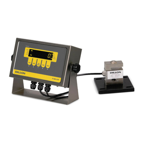
Dillon FI-80 LCD User manual
Dillon
Dillon Quick Balance User manual
Dillon
Dillon FI-90 User manual

Dillon
Dillon ED-2000plus User manual
Dillon
Dillon GTX-Plus Series User manual

Dillon
Dillon AP Dynamometer User manual

Dillon
Dillon EDXtreme EDX-1T User manual
Popular Measuring Instrument manuals by other brands
Camlogic
Camlogic PFG-LP Installation and Maintenance
Oakton
Oakton 35630-00 operating instructions

PCB Piezotronics
PCB Piezotronics ICP 138A25 Installation and operating manual

HP
HP MC68360 user guide
SRS Labs
SRS Labs SXMCMTU64 installation instructions
Extech Instruments
Extech Instruments 407730 user guide

