FunctionFunction
10 isoES425_D00214_00_M_XXEN/01.2019
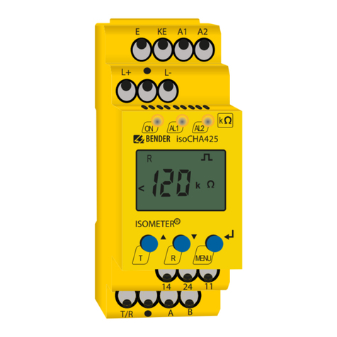
Automatic self test
The device runs a self test after connecting the supply voltage Usand afterwards every 24
hours (selectable at “"t" menu” auf Seite 18 : off, 1h, 24 h).
Manual self test
A self test is initiated by pressing the test button for more than 1.5 s. While pressing the
internal test button "T", all display elements available for this device are shown.
3.2.4 Connection monitoring
The connection monitoring activated by the self test checks the connections of the ter-
minals "E" and "KE" to the protective earth conductor PE. When an error is detected, the
message device error (Err) will be signalled and the error code "E.01" appears on the dis-
play.
The system connection monitoring is used to check the connections of terminals "L1/+"
and "L2/-" to the system to be monitored. When an interruption or a high-resistance con-
nection between L1/+ and L2/- is detected via the internal resistance of the system, the
device error ("Err") is signalled and the error code "E.02" appears on the display. Since a
test of the system connection may take considerable time due to system disturbances or
may even provide incorrect results, the system connection monitoring can be discon-
nected using the parameter "nEt" in the "SEt" menu.
3.2.5 Malfunction
In addition to the described self test, several functions in the insulation monitoring de-
vice are continuously checked during operation. If a fault is detected, the device error
(Err) will be signalled. The error code E.xx appears on the display as an identifier for the
error type xx and the LEDs "ON"/"AL1"/"AL2" flash.
If the error occurs again after restarting the device or after restoring the factory settings,
please contact Bender service.
3.2.6 Alarm assignment of the alarm relays "K1"/"K2"
The messages "device error", "insulation fault", "undervoltage/overvoltage fault", "device
test" and "device start with alarm" can be assigned to the alarm relays via the "out" menu.
An insulation fault is indicated by the messages "+R1", "-R1", "+R2" and "-R2". Messages
"+R1" and "+R2" indicate an insulation fault assigned to conductor L1/+, and messages "-
R1" and "-R2" indicate an insulation fault assigned to conductor L2/-.
The message "test" indicates a self test.
The message "S.AL" indicates a so-called "device start with alarm". After connecting to the
supply voltage Usand setting the parameter value to "S.AL = on", the ISOMETER® starts
with the insulation measured value RF= 0 and sets all activated alarms. The alarms will
only be cleared when the measured values are up-to-date and no thresholds are exceed-
ed. When set to "S.AL = off" (factory setting), the ISOMETER® starts without an alarm. It is
recommended that the "S.AL" parameter value is set identically for both relays.
3.2.7 Measuring and response times
The measuring time is the period essential for the detection of the measuring value. The
measuring time is reflected in the operating time tae . For the insulation resistance meas-
ured value, it is mainly determined by the necessary measuring pulse duration, which de-
pends on the insulation resistance RFand the system leakage capacitance Ceof the
system to be monitored. The measuring pulse is produced by the measuring pulse gen-
erator integrated in the ISOMETER®. The measuring times for Ce, UL1e, UL2e and R% are
synchronous. System disturbances may lead to extended measuring times. In contrast,
the time for the nominal system voltage measurement Unis independent and consider-
ably shorter.
Total response time tan
The total response time tan is the sum of the operating time tae and the response delay
time ton.
Operating time tae
The operating time tae is the time required by the ISOMETER® to determine the insulation
resistance measured value. It depends on the insulation resistance RFand the system
leakage capacitance Ce.
Response delay ton
The response delay ton is set uniformly for all messages in the "t" menu using the param-
eter "ton", whereby each alarm message specified in the alarm assignment hast its own
timer for ton. This delay time can be used for interference suppression in the case of short
measuring times.
An alarm will only be signalled when a threshold value of the respective measuring value
is violated for the period of ton without interruption. Every time the threshold value is vi-
olated within the time ton, the response delay "ton" restarts once again.
Delay on release toff
The delay on release toff can be set uniformly for all messages in the "t" menu using the
parameter "toff", whereby each alarm message specified in the alarm assignment has its
own timer for toff. An alarm will continuously be signalled until the threshold value of the
respective measured value is not violated (including hysteresis) for the period toff without
interruption. Each time the threshold value is not violated for the period toff, the delay on
release "toff" restarts once again.


