AEV Roof Rack User manual

INSTALLATION GUIDE
Roof Rack
AEV30209AC
Last Updated: 07/02/18

PLEASE READ BEFORE YOU START
TO GUARANTEE A QUALITY INSTALLATION, WE RECOMMEND READING THESE INSTRUCTIONS
THOROUGHLY BEFORE BEGINNING ANY WORK. THESE INSTRUCTIONS ASSUME A CERTAIN
AMOUNT OF MECHANICAL ABILITY AND ARE NOT WRITTEN NOR INTENDED FOR SOMEONE NOT
FAMILIAR WITH AUTO REPAIR.
ii
This product is covered under the AEV Parts Limited Warranty, a copy of which can be found at aev-conversions.com/warranty.
INCLUDED PARTS QTY REQUIRED TOOLS
Aluminum Planks 5Basic hand tools
Right Side Rail 1Rivet gun
Left Side Rail 1
End Rails 2
Corners 4
Corner Closeout Plate 4
Corner End Rail Connectors 4
Aluminum Crossbars 5
Roll Bar Brackets 4
Satellite Antenna Bracket 1
Stantion Assemblies 4
AEV logo Decal 4
Alcohol Swab 1
Hardware
NOTE: roof rack may degrade satellite radio reception
Note: The included parts shown below are not necessary
for this application and may be discarded.
1
part i. Platform assembly
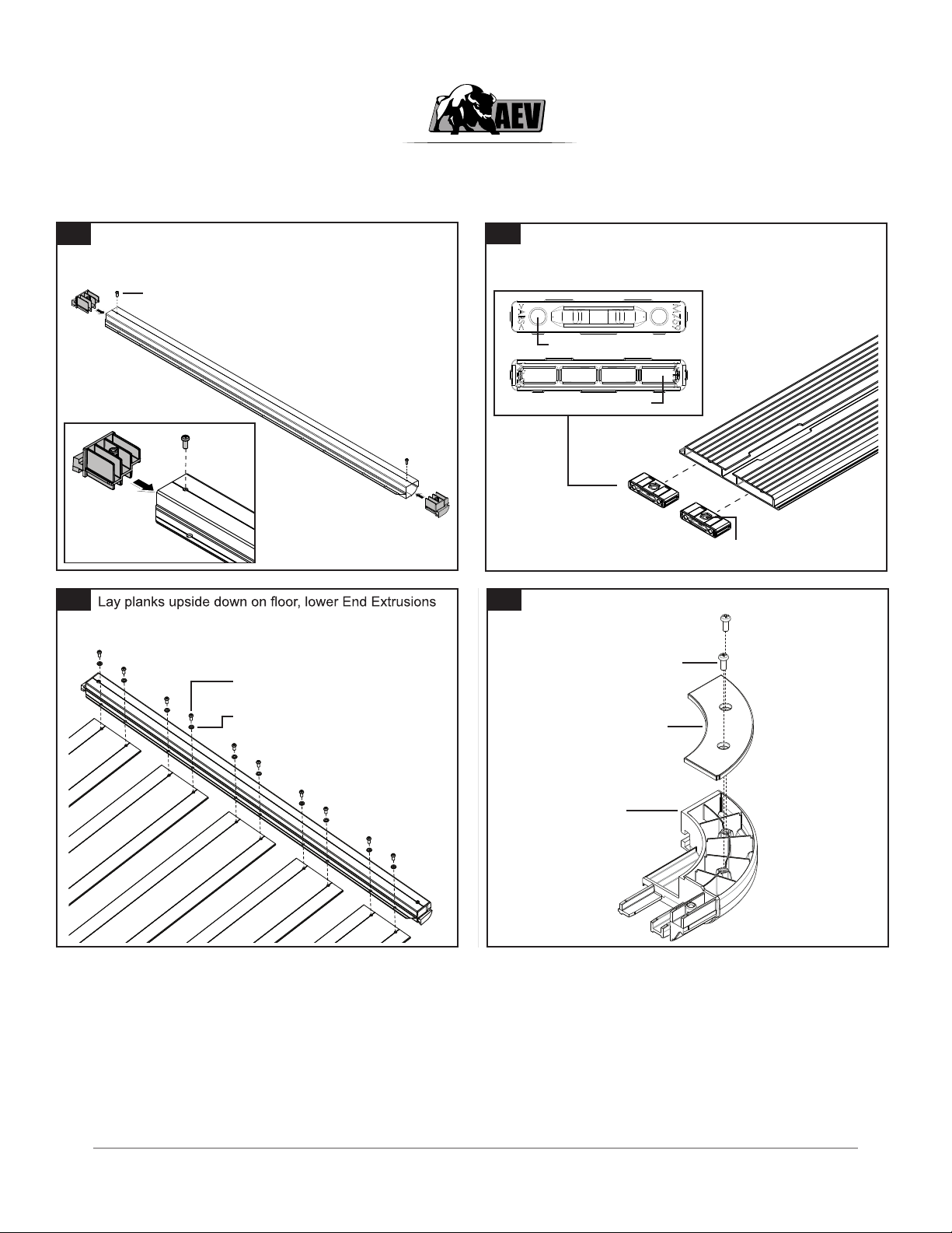
1Fit Corner T Mouldings to the Frame End extrusions. A
rubber mallet can be used to carefully tap the Moulding
in place.
M5x16mm Plastite Screws.
Fit the Plank Inserts into end of plank at both ends.
Orientation of inserts is critical. Carefully tap the Inserts
into place with a rubber mallet.
2
Nyloc Nuts must face up.
Holes face out.
Faces into Plank.
onto planks and fasten together using hardware supplied.
Do the same for the other end.
5
4
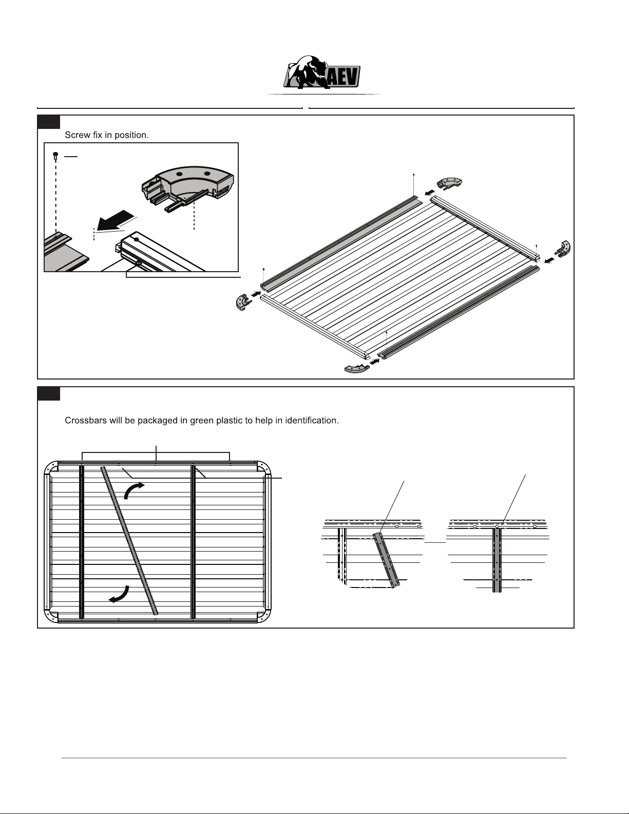
Place side extrusions upside down in position, slide corner mouldings onto T moulding and into extrusion simultaneously.
3
Fit all four cover plates to corner mouldings as shown.
M6x16mm Dome Socket
Head Screw.
M6 OD 12.5mm Flat Washer.
Corner Moulding.
Corner Moulding Cover.
M5x16mm Plastite Screw.
M5x16mm Plastite Screws.
6With the assembly still upside down, place the Crossbars in at an angle and rotate under the lip of the Frame Side
Extrusions. Note: Be sure to use the correct order of Crossbars for the installation as seen bellow ( the AEV Type 1
Before Rotation After Rotation
Cut corners
facing outside
of tray
Crossbar sitting
under bottom lip and
aligned with slot.
Crossbar Type 1 (clear bag)
Crossbar
Type 2
(green bag)
onto planks and fasten together using hardware supplied.
Do the same for the other end.
5
4
Place side extrusions upside down in position, slide corner mouldings onto T moulding and into extrusion simultaneously.
3
Fit all four cover plates to corner mouldings as shown.
M6x16mm Dome Socket
Head Screw.
M6 OD 12.5mm Flat Washer.
Corner Moulding.
Corner Moulding Cover.
M5x16mm Plastite Screw.
M5x16mm Plastite Screws.
6With the assembly still upside down, place the Crossbars in at an angle and rotate under the lip of the Frame Side
Extrusions. Note: Be sure to use the correct order of Crossbars for the installation as seen bellow ( the AEV Type 1
Before Rotation After Rotation
Cut corners
facing outside
of tray
Crossbar sitting
under bottom lip and
aligned with slot.
Crossbar Type 1 (clear bag)
Crossbar
Type 2
(green bag)
2
onto planks and fasten together using hardware supplied.
Do the same for the other end.
5
4
Place side extrusions upside down in position, slide corner mouldings onto T moulding and into extrusion simultaneously.
3Fit all four cover plates to corner mouldings as shown.
M6x16mm Dome Socket
Head Screw.
M6 OD 12.5mm Flat Washer.
Corner Moulding.
Corner Moulding Cover.
M5x16mm Plastite Screw.
M5x16mm Plastite Screws.
6With the assembly still upside down, place the Crossbars in at an angle and rotate under the lip of the Frame Side
Extrusions. Note: Be sure to use the correct order of Crossbars for the installation as seen bellow ( the AEV Type 1
Before Rotation After Rotation
Cut corners
facing outside
of tray
Crossbar sitting
under bottom lip and
aligned with slot.
Crossbar Type 1 (clear bag)
Crossbar
Type 2
(green bag)

3
7
8
9
Place channel nut within the crossbar as shown below and rotate 90 degrees. Place M8x15mm Flat Wahers on top of the
but do not tighten at this stage. Repeat this process for both ends of each crossbars.
M8 x15mm Flat Washer.
M8x20mm Dome Head Screw.
M8 Spring Washer.
M8 Flat Washer OD17.
M8 Channel Nut.
Align crossbars so that the washer sits centred over the slot, you may need to tap the crossbar into position with a rubber
mallet. Once the crossbar is in position tighten bolt with allen key provided.
Washer aligned with slot.
Install the Alloy Locking Tabs. Be aware of the orientation of the of the Single Alloy Tabs on the sides of the Platform.
M6x20mm Security Head Screw.
M6 Spring Washer.
M6 OD 16mm
Flat Washer.
Locking Alloy Tab
Single.
Locking Alloy Tab.
Note the orientations of the Single Locking Alloy Tabs.
Table of contents
Other AEV Automobile Accessories manuals


Popular Automobile Accessories manuals by other brands


ULTIMATE SPEED
ULTIMATE SPEED 279746 Assembly and Safety Advice

SSV Works
SSV Works DF-F65 manual

ULTIMATE SPEED
ULTIMATE SPEED CARBON Assembly and Safety Advice

Witter
Witter F174 Fitting instructions

WeatherTech
WeatherTech No-Drill installation instructions

TAUBENREUTHER
TAUBENREUTHER 1-336050 Installation instruction