AFFINIS GROUP SaniServ AccuFreeze User manual
“Reliability from the team that Serves the Best”
Operation Manual
AccuFreeze Shake Dispensers
SaniServ®
An AFFINIS GROUP Company

Distributor Name: ______________________________________________________
Address: _____________________________________________________________
Phone: _______________________________________________________________
Date of Installation: ____________________________________________________
Model Number: ________________________________________________________
Serial Number: _________________________________________________________
Installer/Service Technician: _____________________________________________
SERVICE: Always contact your SaniServ dealer or
distributor for service questions or service agency
referral. If your SaniServ dealer or distributor cannot
satisfy your service requirements, he is authorized to
contact the factory for resolution.
PARTS: Always order parts from your SaniServ dealer
or distributor. When ordering replacement parts,
specify the part numbers, give the description of the
part, the model number and the serial number of the
machine.
WARRANTY: Remove the Check Test Start (CTS)
form and fill it out in its entirety. Return the original
(white) copy to SaniServ. Dealer/Distributor retain
second (yellow) copy and Owner/Operator retain third
(pink) copy.
The Manufacturer's Limited Warranty is printed on the
reverse side of the Owner/Operator copy.
TO VALIDATE THE WARRANTY, THE CTS FORM
MUST BE COMPLETED AND RETURNED TO THE
FACTORY WITHIN 30 DAYS OF INSTALLATION.
Note: The Check Test Start function must be
performed by a qualified technician.
WARRANTY INFORMATION
I
IMPORTANT

II
Table of Contents
Illustrations
TABLE OF CONTENTS
Installation ......................................................................................................................................................................... 1
Installer’s Preoperational Check........................................................................................................................................ 2
Disassembly and Cleaning ................................................................................................................................................3
Assembly and Lubrication ................................................................................................................................................. 6
Sanitizing ........................................................................................................................................................................... 9
Operation...........................................................................................................................................................................9
Helpful Hints .................................................................................................................................................................... 11
Routine Maintenance....................................................................................................................................................... 12
Consistency Control System ...........................................................................................................................................14
Troubleshooting............................................................................................................................................................... 15
Fig. 1 Leg Installation ................................................................................................................................................... 1
Fig. 2 Control Switch .................................................................................................................................................... 2
Fig. 3 Carburetor Tube ................................................................................................................................................. 3
Fig. 4 Dispensing Product ............................................................................................................................................3
Fig. 5 Front Plate Assembly ......................................................................................................................................... 4
Fig. 6 O-Ring Removal.................................................................................................................................................4
Fig. 7 Carburetor Assembly.......................................................................................................................................... 4
Fig. 8 Dasher Assembly ............................................................................................................................................... 4
Fig. 9a Scraper Blade Removal ..................................................................................................................................... 5
Fig. 9b Scraper Blade Removal ..................................................................................................................................... 5
Fig. 10 Mix Pan Components......................................................................................................................................... 5
Fig. 11 Drip Tray Assembly............................................................................................................................................5
Fig. 12 Stator Rod and Dasher Lubrication .................................................................................................................... 6
Fig. 13 Dasher Assembly ...............................................................................................................................................6
Fig. 14 Scraper Blade Installation and Wear Mark.........................................................................................................6
Fig. 15 Dasher Installation.............................................................................................................................................. 7
Fig. 16 Dasher Installation.............................................................................................................................................. 7
Fig. 17 Dasher (Front View) ...........................................................................................................................................7
Fig. 18 Spigot Plunger Lubrication ................................................................................................................................. 7
Fig. 19 Front Plate Assembly .........................................................................................................................................8
Fig. 20 Mix Pan Assembly..............................................................................................................................................8
Fig. 21 Drip Tray Assembly............................................................................................................................................8
Fig. 22 Carburetor Tube Assembly ................................................................................................................................ 8
Fig. 23 Dispensing Product ............................................................................................................................................ 9
Fig. 24 Control Switch .................................................................................................................................................. 10
Fig. 25 Mix Pan Agitator ...............................................................................................................................................10
Fig. 26 Water Cooled Condenser Valve.......................................................................................................................11
Fig. 27 Scraper Blade Wear Mark ................................................................................................................................ 12
Fig. 28 Drip Chute ........................................................................................................................................................12
Fig. 29 Clean Sharp Condenser Fins........................................................................................................................... 12
Fig. 30 Consistency Adjustment Wiring Box ................................................................................................................ 14
Fig. 31 Consistency Hardness Control.........................................................................................................................14

INTRODUCTION and INSTALLATION
ALWAYS USE A SUFFICIENT NUMBER OF PEOPLE
OR MECHANICAL LIFTING EQUIPMENT TO
PROTECT ALL PERSONNEL FROM PERSONAL
INJURY DURING THE REMAINING STEPS.
1. Raise the machine to install the four legs packed in
the mix pan or the four casters packed in a box on the
skid or on the front mounted drip tray. Be certain all
four are tight! Thread lock is suggested.
2. Carefully lower the machine to the floor and place it
where it will be installed.
3. Level the unit by turning the bottom part of each leg
clockwise or counterclockwise (Fig. 1). The machine
MUST be level to operate properly.
A MINIMUM 6” (152 MM) CLEARANCE MUST BE
MAINTAINED AT THE REAR AND SIDES OF THE
MACHINE FOR ADEQUATE VENTILATION.
ALWAYS CHECK ELECTRICAL SPECIFlCATIONS
ON THE DATA PLATE OF THE MACHINE. THE
DATA PLATE SPECIFICATIONS WILL ALWAYS
SUPERSEDE THE INFORMATION IN THIS MANUAL.
4. Electrical and refrigeration specifications are
located on the data plate on the rear panel of the
individual machines. Consult local authorities for
information regarding plumbing and electrical codes in
your area. Remove the left and right side panels for
power hook-up.
Note: All SaniServ machines should have their
own dedicated circuits to prevent low voltage
conditions caused by other operating equipment.
5. The water line connections on water-cooled
machines is located on the back side of the
machine. The IN/OUT lines are clearly marked and
equipped with 3/4” garden hose fittings.
FAILURE TO PROVIDE FOR PROPER EARTH
GROUND ACCORDING TO LOCAL ELECTRICAL
CODES COULD RESULT IN SERIOUS ELECTRICAL
SHOCK OR DEATH. DO NOT USE EXTENSION
CORDS. INSTALL THE PROPER SIZE WIRE FOR
THE REQUIRED MACHINE AMPS. BE CERTAIN TO
OBSERVE LOCAL CODES IN SELECTING WIRE OR
CORD SIZE AND TYPE.
DO NOT TURN MACHINE
ON UNTIL THE
INSTALLER’S PRE-
OPERATIONAL
CHECK SECTION IS
COMPLETE.
Installation
Fig. 1
Minimum
Clearance
4”(102 mm) for
This manual provides a general system description of the SaniServ AccuFreeze Shake Dispensers. It has been
prepared to assist in the training of personnel on the proper installation, operation, and maintenance of the machines.
Read and fully understand the instructions in this manual before attempting
to install, operate, or perform routine maintenance on the machines.
The following sections of the manual must be performed in sequence:
1. Installation 4. Assembly & Lubrication
2. Installer's Preoperational Check 5. Sanitizing & Operation
3. Disassembly & Cleaning 6. Consistency Adjustment
Introduction
PAGE 1
WARNING
WARNING
IMPORTANT

Installer’s Preoperational Check
THE FOLLOWING ITEMS MUST BE PERFORMED BEFORE ATTEMPTING TO OPERATE THE EQUIPMENT:
INSTALLERS PREOPERATIONAL CHECK PAGE 2
Fig. 2
Control Switch
AUTO
CLEANOUT
O
F
F
O
F
F
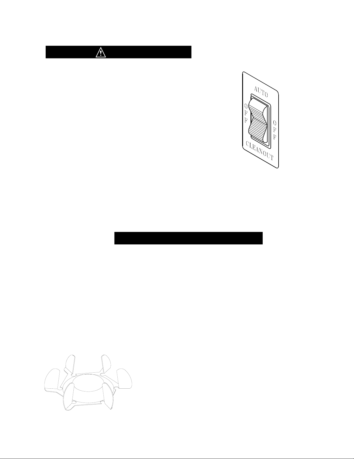
1. Make certain that proper electrical connections have
been made. Plug power cord into power outlet.
2. Set each control switch (Fig. 2) to the “CLEANOUT”
position momentarily to verify the direction of rotation of
the dasher. Looking at the front of the machine, the
dasher should rotate counter-clockwise.
3. Set each control switch to the “OFF” position.
In the event the dasher turns clockwise, STOP and
do not proceed any further
WARNING
UNDER NO CIRCUMSTANCES SHOULD THE UNIT
BE OPERATED IN THE “AUTO” POSITION FOR MORE
THAN THREE MINUTES WITH EMPTY FREEZING
CYLINDERS . DOING SO WILL RESULT IN DAMAGE
TO THE MACHINE.
CAUTION

Emptying Machine
Prior to the disassembly and cleaning of parts, the
machine must be emptied of product. Use the following
procedures (Steps 1 through 3). If this is first time
operation, disregard these steps.
DO NOT INSERT ANY OBJECTS OR TOOLS INTO
THE MIX INLET HOLE, CARBURETOR TUBE HOLE,
OR FRONT PLATE DISPENSING HOLE WHILE THE
MACHINE IS RUNNING. DAMAGE TO THE
MACHINE OR PERSONAL INJURY MAY RESULT.
1. Remove the carburetor tube (Fig. 3) from the mix
inlet hole and lay in the bottom of the mix pan.
2. Set the control switch to the “CLEANOUT” position
and dispense all product from the freezing cylinder by
pulling downward on the spigot handle (Fig. 4) to empty
the machine.
3. Set the control switch to the “OFF” (center) position.
Close the spigot handle before proceeding to cleaning.
Disassembly and Cleaning Procedure
1. Fill the machine with cold water and set the control
switch to the “CLEANOUT” position. DO NOT use
hot water which could damage the machine. Let the
machine agitate briefly and drain the water by pulling
downward on the spigot handle. After the machine is
empty, set the control switch to the “OFF” position.
Repeat the above procedure as necessary to make
certain that all product is removed from the machine.
2. Prepare a suitable detergent and water solution at a
temperature of 125°to 130°F. DO NOT use an
abrasive detergent on any part of the dispenser.
DO NOT USE HOT WATER
DOING SO COULD DAMAGE YOUR MACHINE
3. Fill the mix pan with the cleaning solution. Make
certain that the machine is “OFF”. Clean the mix pan
thoroughly with a brush as the solution drains into the
freezing cylinder. Clean the mix inlet tube and the
carburetor tube holes with the brush provided.
Disassembly & Cleaning
CONSULT YOUR LOCAL HEALTH AGENCY FOR CLEANING AND SANITIZING REQUIREMENTS.
This unit does not come presanitized from the factory. Before serving product, the dispenser must be disassembled,
cleaned, lubricated, and sanitized. These instructions are general guidelines only. Cleaning and sanitizing procedures
must conform to local health agency requirements.
WARNING
DISASSEMBLY & CLEANING
Fig. 3
Carburetor Tube
Fig. 4
Dispensing Product
PAGE 3
IMPORTANT

4. Set the control switch to the “CLEANOUT” position
and agitate for approximately 1 - 2 minutes and then
drain the water by opening the spigot. After the unit is
empty, set the control switch to the “OFF” position.
5. Remove the front plate by turning the black plastic
knobs in a counterclockwise direction (Fig. 5).
Disassemble the front plate in the following manner:
DO NOT USE ANY TOOLS OR SHARP OBJECTS TO
REMOVE ANY O-RINGS FROM THIS MACHINE.
SHARP OBJECTS WILL DAMAGE THE O-RINGS.
a. Remove the faspin and spigot handle.
b. Remove the front plate o-ring.
c. With the spigot handle removed, push the spigot
plunger out the top of the front plate.
d. Remove the o-rings from the spigot plunger by
grasping the part with one hand and with a dry
cloth in the other hand, squeeze the o-ring upward.
When a loop is formed, grasp the o-ring with the
other hand and roll it out of its groove and off the
part (Fig. 6).
6. Remove the carburetor tube (Fig. 7) from the mix
pan. Disassemble and clean in the following manner:
a. Remove the o-ring from the bottom of the carb tube.
b. Clean the inside of the tube with the brush.
7. Remove the dasher assembly (Fig. 8) being careful
not to damage the scraper blades, then disassemble
in the following manner:
a. Remove and take apart the rear seal assembly.
b. Remove the stator rod from the dasher.
C. Remove the blades from the dasher (Fig. 9a)
by first rotating blade upward (Fig. 9b) and then
unsnapping one end from the support rod.
BLADES MUST BE REMOVED FOR CLEANING.
IMPORTANT
DISASSEMBLY & CLEANING
Fig. 5
Face Plate Assembly
Spigot Plunger
Faspin
Spigot
Handle
Front Plate
Front Plate O-ring
DO NOT LUBRICATE
Spigot Plunger
O-rings
Front Plate
Knobs
Fig. 6
O-Ring Removal
Fig. 7
Carburetor Tube Assembly
Scraper
Blade
Rear Seal
Stator Rod
Rear Bearing
Dasher
Fig. 8
Dasher Assembly
PAGE 4
O-ring
Mix
Inlet
Hole
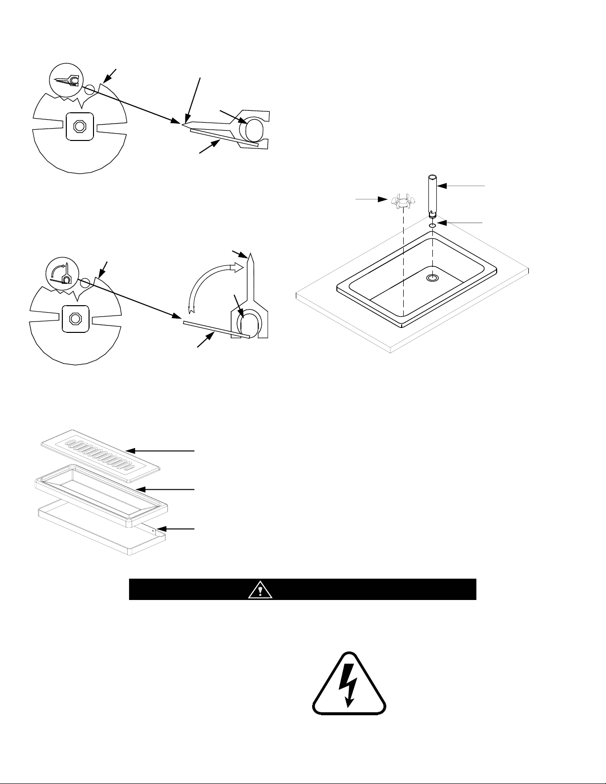
9. Use the small diameter brush to clean all holes and
ports in the parts. DO NOT use an abrasive detergent.
10. After thoroughly washing the parts in the detergent
solution, rinse them in the rinse water. Place the parts
in the sanitizing solution for five (5) minutes and then
air dry to prepare for assembly and lubrication.
DO NOT wipe dry.
11. The remainder of the machine including the mix
pan and freezing cylinder must be cleaned in place
using a mild detergent solution. Clean the exterior with
a damp cloth. DO NOT use an abrasive cleaner on
exterior panels.
Dasher Front
View Scraper Blade
Blade Support
Tab
Support
Rod
Blade Support
Tab
Support
Rod
Dasher Front
View
Scraper Blade
WARNING
DISASSEMBLY & CLEANING
Drip
Drip Tray
Drip Tray
Support
ELECTRICAL
SHOCK HAZARD
Fig. 9a
Scraper Blade Removal
Fig. 9b
Scraper Blade Removal
PAGE 5
WHEN CLEANING THE MACHINE, DO NOT ALLOW EXCESSIVE
AMOUNTS OF WATER AROUND ANY ELECTRICALLY OPERATED COM-
PONENTS OF THE MACHINE. ELECTRICAL SHOCK OR DAMAGE TO
THE MACHINE MAY RESULT.
8. Apply a small amount of SaniGel to the bottom of the
mix pan agitator. Place the lubricated mix pan agitator
into the right front corner of the mix pan. Position the
mix pan agitator until you feel the magnets of the agitator
engage the magnets of the drive system beneath the mix
pan. DO NOT apply lubrication to the Mixout probe
located in the mix pan.
Mix Pan
Agitator
Carburetor
Tube
Carburetor
Tube O-ring
Fig. 10
Mix Pan Components
Fig. 11
Drip Tray
Assembly
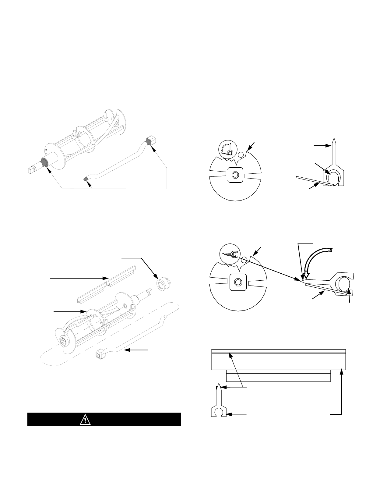
1. Lubricate and assemble the dasher assembly in the
following manner:
a. Apply a generous amount of lubricant to the shoulder
of the dasher and the area of the shaft where the white
plastic portion of the assembled rear seal contacts the
shaft (Fig. 12). This is easily performed by running a 1/4”
bead of lubricant around the shoulder of the dasher.
b. Lubricate the two areas of the stator rod (Fig. 12)
and slide the stator rod into the dasher (Fig. 13). Be
certain that the end of the stator rod is inserted into the
hole at the rear of the dasher.
C. Assemble and install the rear seal with the rubber
portion toward the rear of the freezing cylinder as
indicated in Fig. 13.
DO NOT LUBRICATE THE BACK SIDE OF THE
RUBBER PORTION OF THE SEAL ASSEMBLY.
MACHINE COULD BE DAMAGED.
d. Install the scraper blades on the dasher assembly
by holding the blade perpendicular to the tabs
(Fig. 14a) and then snapping them over the flat area of
the support rod. Then rotate the blade downward in a
counterclockwise direction as viewed from the front of
the dasher (Fig. 14b).
Note: Reverse the blades at each cleaning to maintain
sharpness. In addition, the blades are equipped
with a wear mark (Fig. 14c). When the blade is
worn to this wear mark, they must be replaced.
Assembly & Lubrication
Use only food approved lubricants. Haynes Lubri-Filml (SaniServ part number 1150 is recommended and is available
from your local authorized SaniServ dealer or distributor. Lubrication must be performed daily.
Blade Support
Tab
Support Rod
Dasher Front View
Scraper Blade
Dasher Front
View
Blade Support
Tab Support Rod
Scraper Blade
Rotate Down
Counter
Clockwise
Scraper Blade Wear Mark
End
View
Side
View
ASSEMBLY & LUBRICATION
Lubricate
Shaded
Areas
PAGE 6
Fig. 14c
Scraper Blade Wear Mark
Fig. 14a
Scraper Blade Installation
Fig. 14b
Scraper Blade Installation
Fig. 12
Stator Rod and Dasher Lubrication
CAUTION
Scraper
Blade
Dasher
Stator Rod
Rear Seal and Bearing (Assembled)
Fig. 13
Dasher Assembly
e. Insert the dasher assembly into the freezing cylinder
as far as possible (Fig. 15) being careful not to damage
the scraper blades. Damage will occur to the scraper
blades and the dispenser will not operate properly if the
scraper blades are installed facing in a clockwise
direction (Fig. 16).
Fig. 15
Dasher Installation
Fig. 16
Dasher Installation
Note: The stator rod has been deleted from Fig. 15
and Fig. 16 for clarity only. They must be installed
for proper machine operation.
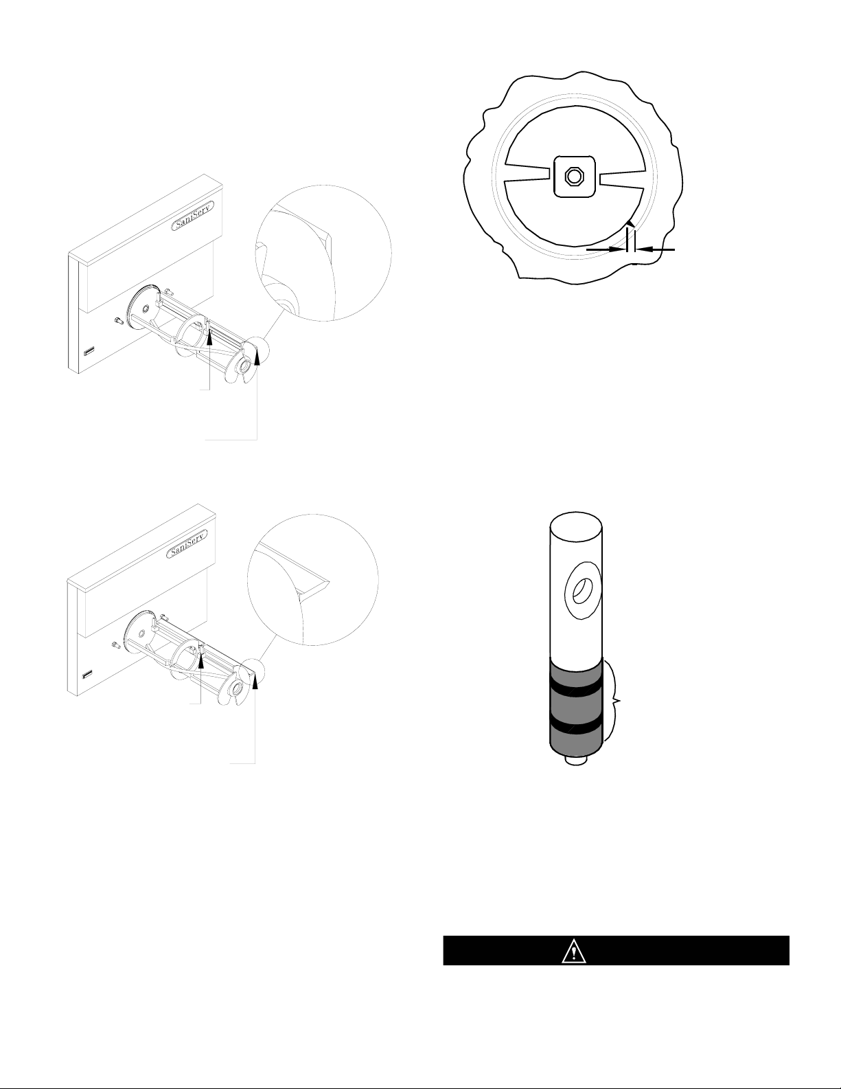
f. While maintaining force against the dasher, rotate it
slowly until the tongue of the dasher engages the
groove in the drive system at the rear of the cylinder.
The outer most portion of the dasher should be
recessed approximately 1/4” to 3/8” inside the freezing
cylinder. No part of the dasher should extend outside
the cylinder. Scraper blades should be visible (Fig. 17)
extending approximately 1/8” beyond the dasher.
.
CORRECT
Blades
Resting On Tabs
Blades Pointing In A
Counterclockwise
Direction
Fig. 17
Dasher with Blade (Front View)
2. Lubricate and assemble the front plate assembly in
the following manner:
a. Install the two o-rings on the spigot plunger by
rolling them onto the plunger. Seat the o-rings in
the grooves. Make certain that they are not twisted.
Smooth the lubricant into the grooves and over
the sides of the plunger assembly (Fig. 18).
Fig. 18
Spigot Plunger Lubrication
b. Slide the lubricated spigot plunger into the front
plate (Fig. 19) Align the spigot handle slot to the front.
c. Insert the spigot handle and secure with the faspin.
d. Install the front plate o-ring.
DO NOT LUBRICATE THE FRONT PLATE O-RING
LUBRICANT WILL MAKE THE FRONT PLATE LEAK
ASSEMBLY & LUBRICATION
Lubricate
Shaded Area
Approximately
1/8” Exposed
Blades Should
Rest On Tabs
Blades Should Not Point
In A Clockwise Direction
INCORRECT
PAGE 7
CAUTION

Fig. 19
Front Plate Assembly
e. Align the front plate to the freezing cylinder, place
the square pocket on the back side of the front plate
over the end of the stator rod, and secure the front
plate assembly to the machine with the two plastic
knobs. Turn both of the knobs in a clockwise direction
simultaneously. Tighten the knobs evenly. DO NOT
tighten one knob all the way down and then the other.
Doing so may result in front plate breakage. Only
moderate force is required. DO NOT over tighten. Set
the spigot plunger to the closed position.
3. DO NOT apply lubrication to the Mix out probe
located in the mix pan - see Fig. 20.
4. Install the drip tray and drip tray insert (Fig. 21).
Fig. 21
Drip Tray Assembly
5. Install the o-ring on the shake carburetor assembly
(Fig. 22). Apply lubricant sparingly over the o-rings.
Place the carburetor tube in the bottom of the mix pan
for sanitizing. Lubricant MUST NOT BLOCK the mix
inlet hole on the carburetor tube.
Fig. 22
Carburetor Tube Assembly
ASSEMBLY & LUBRICATION
Spigot Plunger
Faspin
Spigot
Handle
Front Plate
Front Plate O-ring
DO NOT LUBRICATE
Spigot Plunger
O-rings
Front Plate
Knobs
Drip Tray
Insert
Drip Tray
Drip Tray
Support
Remains
Attached to
Machine
PAGE 8
O-ring
Mix
Inlet
Hole
IMPORTANT
Mixout Probe
Fig. 20
Mix Pan Assembly
6. Proceed directly to the “Sanitizing” section.
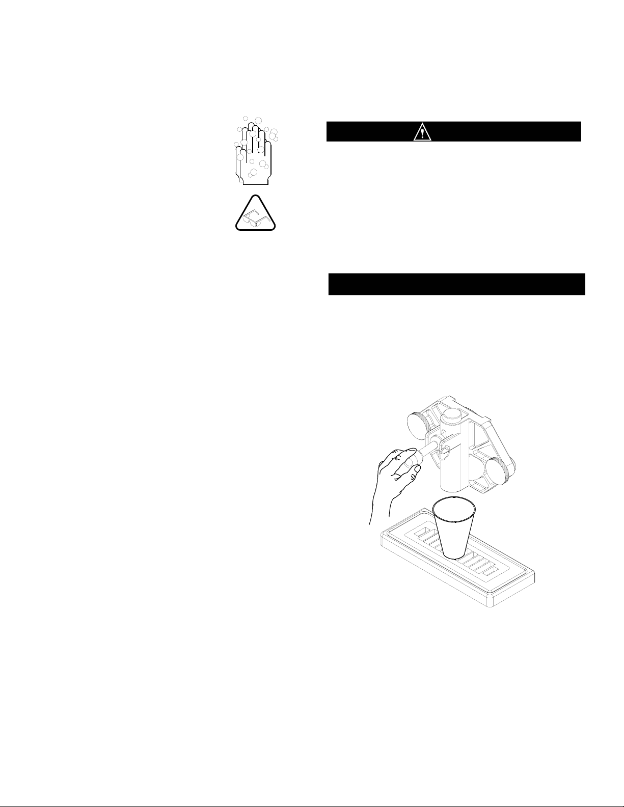
1. Wear eye protection. Wash hands with
a suitable antibacterial soap.
2. Prepare 2 to 3 gallons of sanitizing
solution equivalent to 200 ppm chlorine
residual - check local requirements.
3. Pour the solution into the mix pan.
4. Using a sanitary brush, wipe the
solution onto the sides of the mix pan,
over the mix out probe, and the underside of the lid.
5. Set the control switch to the “CLEANOUT” position
and let the unit agitate for approximately 3 to 5 minutes.
NOTE: DO NOT set the control switch to the “AUTO”
position. Doing so would freeze the sanitizing
DO NOT INSERT ANY TOOLS OR OBJECTS INTO
THE MIX INLET HOLE, CARBURETOR TUBE HOLE,
OR THE DISPENSING HOLE IN THE FRONT PLATE.
DAMAGE TO THE MACHINE OR PERSONAL INJURY
MAY RESULT.
6. Set the control switch to the “OFF” position and
drain the solution from the machine. Proceed directly
to the “Operation” section of this manual.
DO NOT RINSE OUT THE MACHINE
Sanitizing
Prior to operation, the machine must be sanitized. The unit must have already been cleaned and lubricated.
Note: Sanitize immediately before use, not several hours before or the previous evening.
WARNING
IMPORTANT
Operation
Always start with a cleaned and sanitized dispenser as per previous instructions. Use only fresh mix when charging the
units. Following these instructions is critical to the maximum operating efficiency of the machine.
1. Remove the carburetor tube from the bottom of the
mix pan and set aside in a sanitary location.
2. Place a 16 oz. Cup under the spigot and open the
spigot handle. Pour approximately one quart of fresh
product mix into the mix pan. (This will chase the
sanitizing solution from the mix pan and freezing
cylinder.) Close the spigot handle when the sanitizer
is purged from the system. (Fig. 23).
3. Once the sanitizer solution has been purged from
the machine, fill the mix pan full of product mix.
(carburetor tube is not installed). Bubbling is normal.
NOTE: DO NOT POUR SHAKE PRODUCT MIX
DIRECTLY ONTO THE MIX PAN AGITATOR WHEN
YOU FILL THE MACHINE.
Fig. 23
Dispensing Product
PAGE 9
SANITIZING & OPERATION
Prior to proceeding, make sure that the carburetor
tube holes are clean and free of old product debris
or lubricant. A blocked carburetor tube will cause
incorrect product consistency and/or damage the
machine if product should freeze too thick.
4. Once mix pan is at least one-half full, and bubbling
has ceased, install the carburetor tube into the hole in
the mix pan with a gentle twisting motion.
5. Move the control switch to the “AUTO” position
and the unit will start in 3-5 seconds.
6. Allow the compressor to cycle 3-4 times dispensing
a sample of the product after each cycle to check for
consistency. If the machine is not dispensing the
product at the desired consistency after four full cycles,
refer to the Consistency Control Section of this manual.
Initial pull-down time is 10-15 minutes, but may vary
due to product mix and ambient conditions.
8. Replace the mix pan lid and always operate the
machine with the lid on the mix pan reservoir.
There must be product in the mix pan for machine
to start.
NOTE: WHEN REFILLING THE MIX PAN DURING
DAILY OPERATION, DO NOT POUR SHAKE OR
SOFT SERVE MIX DIRECTLY ONTO THE MIX PAN
AGITATOR.
If the agitator stops turning during machine operation,
a. turn off the machine
b. reposition the agitator with a sanitized utensil - see
sanitizing instructions for sanitizing procedure
c. follow the instructions for starting the machine.
PAGE 10
IMPORTANT
Fig. 24
Control Switch
CAUTION
OPERATION
Fig. 25
Mix Pan Agitator

Helpful Hints
HELPFUL HINTS
PAGE 11
Front Plate: This component is the plastic device from
which the product is dispensed. It is designed and
manufactured for strength and durability. However,
through improper use, the front plate can be damaged.
Use the following information for proper care:
a. Do not over tighten the knobs.
b. Always tighten knobs evenly. Do not attempt to
turn one knob all the way down and then one of
the other three knobs. Doing so will bind the front
plate and could result in breakage.
c. Improper installation of the stator rods can cause
breakage. The stator rods must be properly
seated in the dasher before installing the front
plate. If the stator rods are improperly installed,
subsequent tightening of the knobs will break the
front plate.
d. DO NOT attempt to wash the front plate or any
other components in a dishwasher.
Mix Out Light: When the mix out light comes on, the
mix pan is low on mix. The mix pan must be filled with
fresh product mix immediately to prevent air from
entering the freezing cylinder starving the machine and
causing freeze-up and vibration. If this condition occurs,
set the selector switch to the “OFF” position. Remove
the carburetor tube and add mix to the low mix pan until
the freezing cylinder stops bubbling. Replace the
carburetor tube with a gentle twist, then return the
control switch to the “AUTO” position.
Filling: Always fill the machine with fresh product at the
start of each day.
Drip Tray: This should be removed daily and cleaned
to remove residue.
Mix Pan Lid: Be certain to leave the lid in place on top
of the machine to prevent any foreign materials from
contaminating the mix.
Mixing: Make certain that the product mix is prepared
according to label instructions.
Sanitizing: Do not soak plastic parts in sanitizer
overnight. Doing so can cause the plastic parts to
become brittle and lead to premature failure.
Mix Pan Agitator: If the mix pan agitator stops turning
during operation of the machine, turn off the machine,
reposition the agitator with a sanitized utensil, and
follow the instructions for starting the machine.
DO NOT POUR PRODUCT MIX DIRECTLY ONTO
THE AGITATOR WHEN YOU FILL THE MACHINE.
Treat the mix pan agitators as any other small parts
such as the scraper blades. Follow the same cleaning
and sanitizing instructions.
Winter Storage: To protect the unit during seasonal
shut-down, it is important that the dispenser be stored
in the proper manner. Use the following procedures:
1. Turn off ALL power to the machine.
2. Wash all parts that come in contact with the mix
with a warm mild detergent solution. Rinse in clear
water and dry parts thoroughly.
3. Store the loose parts such as the mix pan
components, front plate parts, and the dasher
assembly parts outside of the machine.
4. Do not lay heavy objects on the plastic or rubber
parts.
5. Cover the machine and all loose parts to protect
them from dust or other contaminants while in
storage. Place the machine in a dry location.
6. On water-cooled units, disconnect the water
lines. Use compressed air to blow out all
remaining water in the condenser. Insert a
screwdriver (Fig. 26) to open the water valve.
Note: Failure to purge the machine of water
can result in severe damage to the cooling
system. This task should be performed by a
qualified service technician.
Fig. 26
Water-Cooled
Condenser Valve

Routine Maintenance (Trained Service Technician)
Routine Maintenance (Owner-Operator)
ROUTINE MAINTENANCE
Scraper Blade Wear Mark
End
View
Side
View
Fig. 27
Scraper Blade Wear Mark
CONDENSER FINS ARE VERY SHARP
USE EXTREME CAUTION WHEN CLEANING
Quarterly: Thoroughly clean the condenser fins on all
air-cooled machines. Remove all lint and dust with a
vacuum cleaner or compressed air (Fig. 29) to clean
fins. A dirty condenser greatly reduces refrigeration
capacity and efficiency. When using compressed air,
place a damp cloth on the opposite side of the
condenser to catch the flying dirt or lint.
Annually: Check the belts for signs of wear or cracking.
Remove panels and clean all parts inside of the machine
including the base, side panels, fan blades, condensers,
etc.
Fig. 28
Drip Chute
DISCONNECT THE MACHINE FROM ITS POWER
SOURCE(S) BEFORE PERFORMING ANY ROUTINE
MAINTENANCE. PERSONAL INJURY OR DAMAGE
TO THE MACHINE COULD RESULT IF THIS
PRACTICE IS NOT OBSERVED.
Daily: Inspect the machine for signs of product leaks
past seals and gaskets. If proper assembly does not
stop leaks around gaskets or seals, check for improper
lubrication and worn or damaged parts. Replace parts
as needed.
Periodically: Inspect the scraper blades (Fig. 27) to
see that they are straight and sharp. If worn, damaged
or warped, the blades will not scrape the cylinder walls
correctly and the freezing capacity will be reduced.
Clean the drip chute assembly (Fig. 28) with warm water
and detergent solution.
Fig. 29
Clean Sharp Condenser Fins
WARNING
WARNING
PAGE 12

This page intentionally blank
PAGE 13
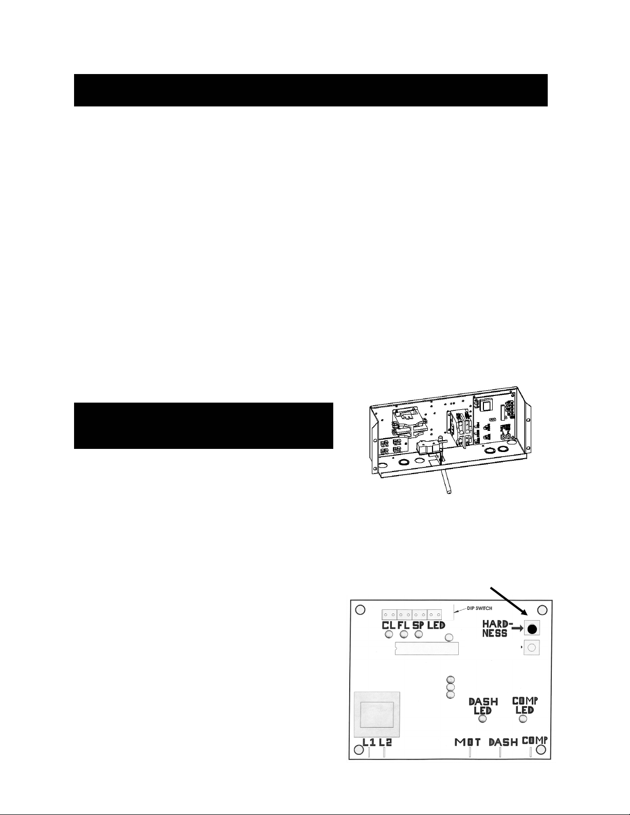
Consistency Adjustment
Consistency adjustment is done by adjusting the
potentiometer on the electronic control board (ECB).
The ECB is located behind the front wiring box cover
above the front dispensing plate.
1. Remove two Phillips screws on the underneath
side of the wiring box cover. The ECB is located
on the left side of the wiring box as show in Fig. 30.
2. Locate the black potentiometer labeled
HARDNESS as shown in Fig. 31. By turning the
potentiometer to the right (clockwise) it will
increase the thickness and lower the product
temperature. Turning the potentiometer to the left
(counter clockwise) will decrease the thickness and
raise the temperature.
3. Reinstall the wiring box cover and reconnect the
power.
4. Run the unit with product and allow the
refrigeration system to cycle TWO times.
5. Draw product from the machine and check for
desired consistency.
6. Repeat procedure if required.
NOTE: ONLY TURN THE POTENTIOMETER IN
SMALL INCREAMENTS.
If you cannot adjust the product consistency to your
desired thickness, contact your local Certified
SaniServ Service Provider.
CONSISTENCY ADJUSTMENT
Fig. 31
Hardness Control
CAUTION
BEFORE PROCEEDING
DISCONNECT THE POWER
Electronic Consistency Control
This machine is designed with an electronic control board to manufacture Frozen Shake Beverage
Only! Do not attempt to operate the machine with other type products. Operating unit with non-
shake products will damage the machine and factory warranty will be voided.
DO NOT ADJUST THE MACHINE!
Improper consistency is due to improperly mixed product
This equipment has been tested at the factory with shake product and has been shipped with FACTORY
PRE-SETS. Shake product temperature will range from 25-28 degrees. If you feel a consistency adjust-
ment is needed, check the temperature of the dispensed product before making an adjustment. If your
product is within these temperature ranges and the consistency is incorrect, you may have improperly
mixed product.
ADJUSTING THE MACHINE TO COMPENSATE FOR IMPROPERLY MIXED PRODUCT MAY CAUSE
PRE-MATURE COMPONENT FAILURE AND MAY VOID WARRANTY.
CAUTION !
PAGE 14
Fig. 30
Wiring Box
SH

TROUBLESHOOTING GUIDE
PAGE 15
Please make these simple checks prior to contacting you service provider. Because adjustments to the machine are not covered
under the terms of warranty, these tips can save you time and money. If you feel you are not comfortable performing trouble-shooting
su
gg
estions
,
p
lease contact
y
our local certified service
p
rovider.
Machine will
not start
Make sure electrical cord is correctly seated in the electrical receptacle.
Check circuit breaker in electrical panel.
Product is
Soft
Do not make a consistency adjustment at this point. Always check product temperature first. Should be
between 25-28 degrees. If using a soft serve product and temperature is lower than listed, product is
broken down. See Product Breakdown in glossary section. Replace with fresh product.
Check for properly mixed product. Replace as necessary
If using Re-run product, remove product and add fresh mix.
Confirm that the carbtube has been installed. Product will not thicken without carbtube.
Check for dull scraper blades. Blades should be sharp. Replace every 6 months.
Check Condenser for dirt or obstructions. See Quarterly Maintenance
Confirm that the condenser fan is running.
Confirm 6” of airflow on all both sides and back of machine.
High ambient temperature. Recommended machine ambient temperature not to exceed 82 degrees.
Product is too
Thick
Check for properly mixed product.
Confirm freezing cylinder is not starved of product. See glossary (Starved Cylinder)
Check product temperature. Should be betwee 25-28 degrees.
Check for missing scraper blade or stator rod. Check dasher assemblies.
Check for sticking spigot lever and or switch. If stuck in the up position, will cause unit to run continually.
Front Plate
Leaking
Confirm front plate o-ring is not ripped or torn. Replace if necessary. Replace seals and o-rings every six
months.
Do not lubricate front plate o-ring.
Confirm spigot plunger o-rings are not ripped or torn. Replace if necessary. Replace every six months.
Confirm spigot plunger o-rings are lubricated daily.
Tighten front plate knobs evenly.
Confirm stator rod is not worn or grooved.
Product
leaking from
the drip chute
and or drip
tube.
Rear Seal is worn. Replace. Note: Replace seals, o-rings and gaskets every six months.
Do Not Lubricate the rubber portion of the rear seal
The shaft of the dasher where the rear seal is installed must be lubricated daily.
Confirm stator rod is not worn or grooved.
Front plate knobs loose.
Squeaking ,
chirping
noises and or
vibration
heard.
Use properly mixed product. Replace as necessary.
Confirm freezing cylinder is not starved of product. See glossary (Starved Cylinder)
Check lubrication
Confirm all panel screws are installed and tightened
Adjust width of drip tray bracket.
Check for dull scraper blades. Blades should be sharp. Replace every 6 months.
Product in
mix-pan too
warm. (soft
serve /shake
machines)
Refrigerate product prior to use.
Confirm storage source of product at 40 degrees or below.
Maintain product level of ½ to ¾ full in mix-pan reservoir.
Confirm magnetic agitator is installed and turning.
Mix-pan lid must be installed at all times to prevent foreign materials contaminating product and to insulate
product in the mix-pan .
Who to
contact for
service and
parts
If you do not have a local service and parts provider, contact your SaniServ Dealer/Distributor. Visit
www.saniserv.com to locate a Distributor (Sales Section) or a Service Agent (Technical Support Section).
Note: Refer to
g
lossar
y
for those items selected in bold.
Standard Units

TROUBLESHOOTING GLOSSARY
Troubleshooting Glossary
Ambient Temperature. The temperature of the air in the immediate vicinity of the operating machine. High am-
bient temperature can reduce the capacity with an air-cooled condenser.
Capacity. The total capacity of frozen product that a freezer can produce in a given period usually stated in gal-
lons per hour (G.P.H.).
Carbtube. Flow control device that allows product and air to be blended together. The air added to the product is
labeled as over-run. The over-run helps provide a thick and rich product. If the carbtube is not used the product
will be heavy, wet, grainy, will not thicken and product temperatures will be lower than the specified 18-21 degrees
soft serve and 25-28 degrees shake. Carbtubes are not used in frozen beverage machines.
Condenser. The part of the refrigeration mechanism that receives hot, high-pressure refrigeration gas from the
compressor and cools gaseous refrigerant until it returns to a liquid state.
Consistency. The viscosity or thickness of the product in the freezing cylinder.
Consistency Control. A control that senses the thickness or viscosity of the product in the freezing cylinder.
Dasher. The part of the freezer that scrapes frozen product off the inside of the freezing cylinder and blends the
product. In a gravity freezer, this assembly also moves the product forward to be dispensed.
Front Plate. Seals the front of the freezing cylinder and provides a means for dispensing the product. On gravity
fed freezers, the front plate indirectly holds the dasher in place via the stator rod. It also provides compression for
the rear seal.
Freezing Cylinder. The part of the refrigeration mechanism in which the refrigerant vaporizes and absorbs heat.
This is the part of the freezer where the liquid product is frozen.
Magnetic Agitator. Installed in the mix-pan reservoir and used to maintain product temperatures and prevent
product separation. The bottom of the agitator must be lubricated.
Mix-pan. Is the top container that product is poured into. It is used as storage until product is needed for the
freezing cylinder. Soft Serve and Shake machines have refrigerated mix-pans to prevent bacteria from forming.
Mixing Product / Product Temperatures. If your using a product that has to be mixed with water or other ingre-
dients, it is imperative the product is mixed consistently everyday. If not, the machine will not run consistent and
could possibly damage components. This is very important with frozen (slush) beverages. Always mix to the
product manufactures recommendations. The machine is designed to operate with a frozen product that falls
within these temperatures (soft serve 18-21 degrees, yogurt 17-20 degrees, shake 25-28 degrees, non-alcoholic
frozen beverage 25-28 degrees and alcoholic frozen beverage 18-22 degrees).
Overrun. The volumetric increase of product from the liquid to the solid state due to the incorporation of air into
the frozen product. Overrun is states as a percentage.
Product Breakdown. The decline in frozen product quality resulting from excess agitation or temperature varia-
tions of product that has been in the freezing cylinder too long. Product, which has broken down, may be grainy,
wet and or heavy. Product breakdown is easily detected by taking the temperature of the dispensed product.
Temperatures will always be lower than recommended product temperatures.
PAGE 16

TROUBLESHOOTING GLOSSARY
Troubleshooting Glossary
Rear Seal. This part is stationary during operation and must not move. When installed and lubed properly, seals
mix in cylinder. When installed and lubed improperly, it causes main shafted bearing failure.
Rerun. The reuse of previously frozen product after it has melted to a liquid. Rerun is obtained when emptying a
freezer for periodic cleaning. Use caution when using rerun as it may contain high bacteria or Coli count, which
could contaminate the fresh mix with which it is combined. Freezers should never be started with rerun. If used at
all, it should be blended with fresh mix at a ratio of seven parts new mix with three parts old mix, after initial
freeze-down with fresh mix.
Scraper Blades. The component that scrapes the frozen product from the freezing cylinder surface. Blades must
be sharp, as dull blades will leave product on the freezing cylinder, insulating the mix from the refrigerant.
Spinner Assembly. An externally installed or internally installed component used to blend a base product with
flavoring or other particulate.
Spigot Plunger. The mechanism on the front plate through which the product is dispensed.
Starved Cylinder. A starved cylinder is often mistaken for a freeze up or product too thick. A starved cylinder
(starving) is created when a larger percentage of frozen product is dispensed from the freezing cylinder than the
percentage of liquid product entering the freezing cylinder from the mix-pan. There are several causes of starving.
1. Overdrawing: Dispensing more product from the machine than it’s designed to do. This would occur if a ma-
chine were undersized for its application.
2. Inserting the carbtube prior to pouring the initial product into the mix-pan at the start of each day. This forms a
vacuum and traps a large percentage of air in the cylinder; therefore the cylinder will not fill with product.
3. When carbtube hole setting is not set on the correct hole size for the amount of product being drawn. Exam-
ple, if several customer dispense product from the machine with the carbtube set on the small hole, it will not
allow the freezing cylinder to be replenished with product in a timely manner. Change carbtube setting to a
larger hole.
4. Carbtube not being cleaned, thus allowing product build-up in the carbtube holes. This restricts product from
entering the freezing cylinder.
5. Mix out light not working therefore not alerting operator the need to add product.
6. Pouring frozen or semi frozen product into the mix-pan reservoir. This will form a blockage in the carbtube
hole and not allow liquid product to flow into the cylinder.
7. Mix-pan too cold, allowing product to freeze in mix-pan and restricting product flow.
Stator Rod. Acts as a bearing surface. Helps enfold air for overrun. Transmits compression to the rear seal.
Helps mechanical torque system sense torque. Be sure to lubricate.
PAGE 17
Table of contents
Other AFFINIS GROUP Dispenser manuals

Popular Dispenser manuals by other brands

Sureshot Dispensing Systems
Sureshot Dispensing Systems AC2-GP Operation manual

Hatco
Hatco ATMOSPHERIC AWD-12 Series Installation and operating manual

Georgia Pacific
Georgia Pacific 54010 reference guide

Toto
Toto TS125R quick start guide

BOWMAN
BOWMAN Signature BD111-0033 Installation

Metasys
Metasys META TOUCH Instructions for use


