AFFINIS GROUP SanisServ 500 Series User manual

Operation Manual
500 Series
Soft Serve Twist Dispensers
SaniServ®
An AFFINIS GROUP Company
“Reliability from the team that Serves the Best”
Total Restaurant Supply - https://totalsupply1.com - Toll Free 1-800-944-9304 - Local 507-288-9454
2940 Hwy 14 W, Rochester, MN 55901
Distributor Name: _______________________________________________________
Address: ______________________________________________________________
Phone: _______________________________________________________________
Date of Installation: _____________________________________________________
Model Number: ________________________________________________________
Serial Number: _________________________________________________________
Installer/Service Technician: _____________________________________________
SERVICE: Always contact your SaniServ dealer or
distributor for service questions or service agency
referral. If your SaniServ dealer or distributor cannot
satisfy your service requirements, he is authorized to
contact the factory for resolution.
PARTS: Always order parts from your SaniServ dealer
or distributor. When ordering replacement parts, specify
the part numbers, give the description of the part, the
model number and the serial number of the machine.
WARRANTY: Remove the Check Test Start (CTS) form
and fill it out in its entirety. Return the original (white)
copy to SaniServ. The Dealer/Distributor retains the
second (yellow) copy and the Owner/Operator retains the
third (pink) copy.
The Manufacturer's Limited Warranty is printed on the
reverse side of the Owner/Operator copy.
TO VALIDATE THE WARRANTY, THE CTS FORM
MUST BE COMPLETED AND RETURNED TO THE
FACTORY WITHIN 30 DAYS OF INSTALLATION.
Note: The Check Test Start function must be performed
by a qualified technician.
WARRANTY INFORMATION
I
IMPORTANT
Total Restaurant Supply - https://totalsupply1.com - Toll Free 1-800-944-9304 - Local 507-288-9454
2940 Hwy 14 W, Rochester, MN 55901
Introduction........................................................................................................................................................................1
Installation..........................................................................................................................................................................1
Installer’s Preoperational Check........................................................................................................................................2
Disassembly and Cleaning................................................................................................................................................3
Assembly and Lubrication .................................................................................................................................................7
Sanitizing & Operation.....................................................................................................................................................10
Consistency Adjustment..................................................................................................................................................12
Routine Maintenance.......................................................................................................................................................13
Helpful Hints ....................................................................................................................................................................14
Troubleshooting...............................................................................................................................................................15
Service Record................................................................................................................................................................16
Fig. 1 Leg Installation...................................................................................................................................................1
Fig. 2 Control Switch....................................................................................................................................................2
Fig. 5 Carburetor Tube ................................................................................................................................................3
Fig. 6 Dispensing Product............................................................................................................................................3
Fig. 7 Front Plate Assembly.........................................................................................................................................4
Fig. 8 Front Plate Gasket Removal..............................................................................................................................4
Fig. 9 Spigot Plunger O-ring Removal..........................................................................................................................4
Fig. 10 Dasher Assemblies ............................................................................................................................................5
Fig. 11 Carburetor Tube ................................................................................................................................................5
Fig. 12 Mix Pan Reservoir Agitator.................................................................................................................................6
Fig. 13 Drip Tray Assembly............................................................................................................................................6
Fig. 14 Front Plate Assembly.........................................................................................................................................6
Fig. 15 Stator Rod and Dasher Lubrication....................................................................................................................7
Fig. 16 Stator Rod and Dasher Assemblies...................................................................................................................7
Fig. 17 Scraper Blade Assembly....................................................................................................................................8
Fig. 18 Dasher (Front View)...........................................................................................................................................8
Fig. 19 Spigot Plunger Lubrication.................................................................................................................................8
Fig. 20 Front Plate Assembly.........................................................................................................................................8
Fig. 21 Front Plate Gasket Installation...........................................................................................................................9
Fig. 22 Front Plate Assembly.........................................................................................................................................9
Fig. 23 Carburetor Tube ................................................................................................................................................9
Fig. 24 Mix Pan Components.........................................................................................................................................9
Fig. 25 Mix Pan Reservoir Mixout Probe.....................................................................................................................10
Fig. 26 Control Switch..................................................................................................................................................10
Fig. 27 Dispensing Product..........................................................................................................................................10
Fig. 29 Control Switch..................................................................................................................................................11
Fig. 30 Electronic Consistency Control Board..............................................................................................................12
Fig. 31 Spring Adjustment Mechanism.........................................................................................................................13
Fig. 32 Water-Cooled Condenser Flow Control Valve .................................................................................................14
Illustrations
Table of Contents
II
TABLE OF CONTENTS
Total Restaurant Supply - https://totalsupply1.com - Toll Free 1-800-944-9304 - Local 507-288-9454
2940 Hwy 14 W, Rochester, MN 55901
Introduction
ALWAYS CHECK ELECTRICAL SPECIFlCATIONS
ON THE DATA PLATE OF THE MACHINE. THE DATA
PLATE SPECIFICATIONS WILL ALWAYS
SUPERSEDE THE INFORMATION IN THIS MANUAL.
4. Electrical and refrigeration specifications are
located on the data plate on the rear panel of the
individual machines. Consult local authorities for
information regarding plumbing and electrical codes in
your area. Model 522 has two power hook-ups, 30
amps for single phase or 20 amps for three phase per
side. When operating only the right side on 522 models,
power must be applied to the left side for the cooling
fans to operate. Remove the left and right side panels
for power hook-up.
Note: All SaniServ machines should have their own
dedicated circuits to prevent low voltage conditions
caused by other operating equipment.
5. The water line connections on water-cooled
machines are located on the back side of the machine.
The IN/OUT lines are clearly marked and equipped
with 3/4” garden hose fittings.
Note: These water lines are installed on water-cooled
machines only.
FAILURE TO PROVIDE FOR PROPER EARTH
GROUND ACCORDING TO LOCAL ELECTRICAL
CODES COULD RESULT IN SERIOUS
ELECTRICAL SHOCK OR DEATH.
DO NOT USE EXTENSION CORDS
DO NOT TURN MACHINE ON
INTRODUCTION & INSTALLATION
This manual provides a general system description of the SaniServ Soft Serve Twist Dispensers. It has been prepared to
assist in the training of personnel on the proper installation, operation, and maintenance of the machines.
Please read and fully understand the instructions in this manual before attempting to install, operate, or perform routine
maintenance on the machines.
The following sections of the manual must be performed in sequence:
1. Installation 4. Assembly & Lubrication
2. Installer's Preoperational Check 5. Sanitizing & Operation
3. Disassembly & Cleaning 6. Consistency Adjustment
PAGE 1
IMPORTANT
WARNING
Installation
ALWAYS USE A SUFFICIENT NUMBER OF PEOPLE
OR MECHANICAL LIFTING EQUIPMENT TO
PROTECT ALL PERSONNEL FROM PERSONAL
INJURY DURING THE REMAINING STEPS.
1. Raise the machine to install the four legs packed in
the mix pan or the four casters packed in a box on the
skid or on the front mounted drip tray. Be certain all
four are tight! Thread lock is suggested.
2. Carefully lower the machine to the floor and place it
where it will be installed.
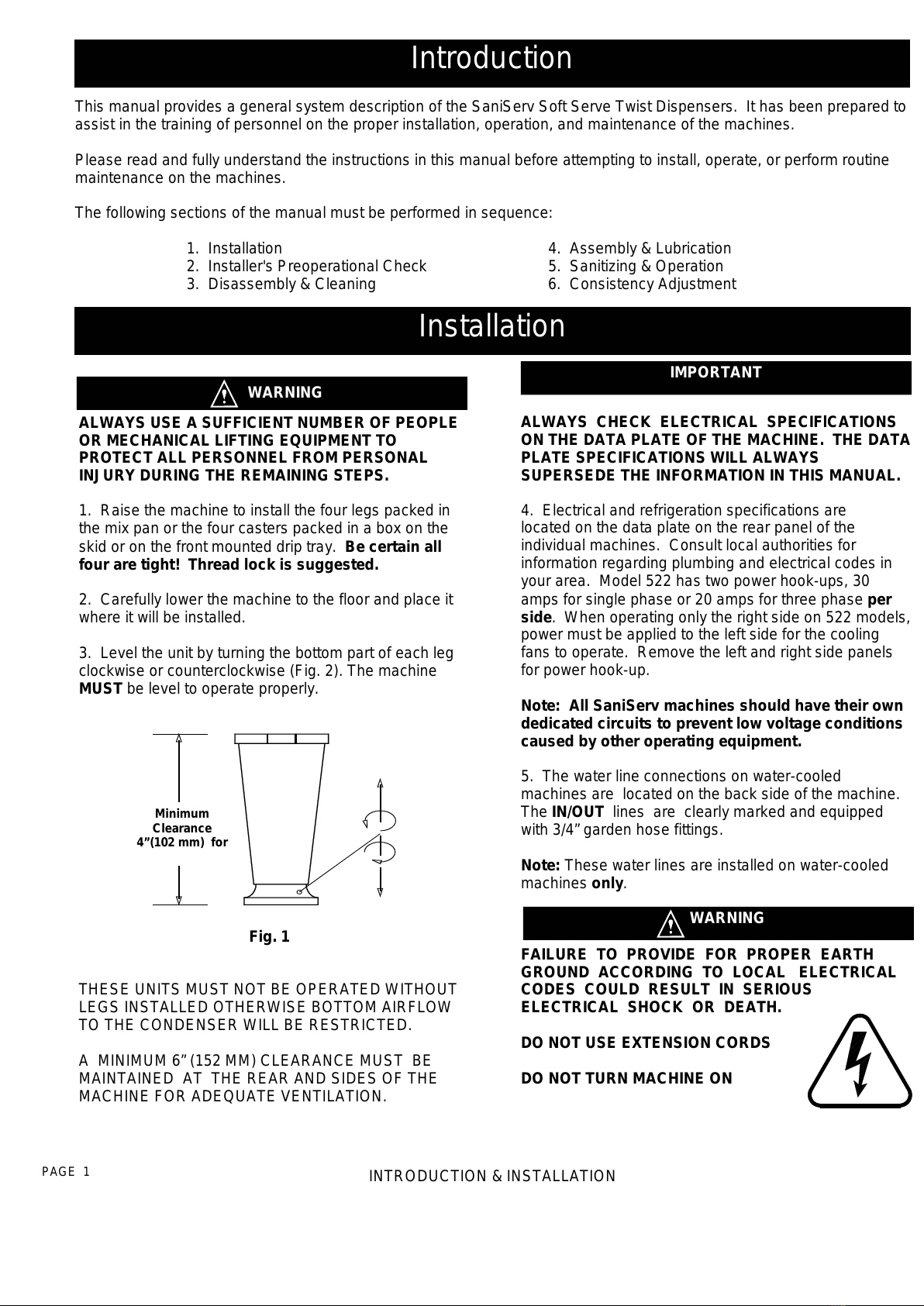
3. Level the unit by turning the bottom part of each leg
clockwise or counterclockwise (Fig. 2). The machine
MUST be level to operate properly.
THESE UNITS MUST NOT BE OPERATED WITHOUT
LEGS INSTALLED OTHERWISE BOTTOM AIRFLOW
TO THE CONDENSER WILL BE RESTRICTED.
A MINIMUM 6” (152 MM) CLEARANCE MUST BE
MAINTAINED AT THE REAR AND SIDES OF THE
MACHINE FOR ADEQUATE VENTILATION.
Fig. 1
Minimum
Clearance
4”(102 mm) for
WARNING
Total Restaurant Supply - https://totalsupply1.com - Toll Free 1-800-944-9304 - Local 507-288-9454
2940 Hwy 14 W, Rochester, MN 55901
Installer’s Preoperational Check
THE FOLLOWING ITEMS MUST BE PERFORMED BEFORE ATTEMPTING TO OPERATE THE EQUIPMENT.
INSTALLER’S PREOPERATIONAL CHECK PAGE 2
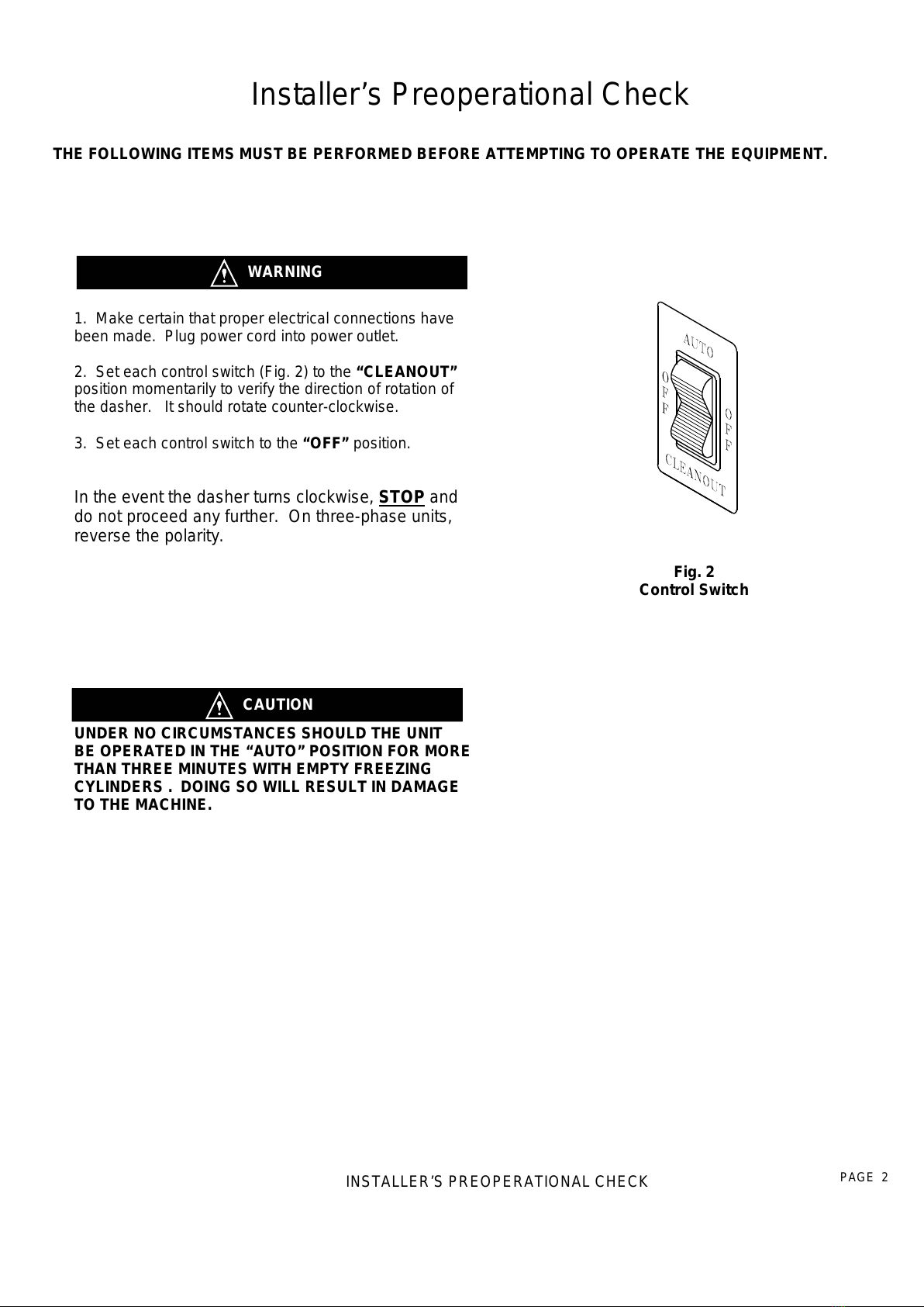
Fig. 2
Control Switch
1. Make certain that proper electrical connections have
been made. Plug power cord into power outlet.
2. Set each control switch (Fig. 2) to the “CLEANOUT”
position momentarily to verify the direction of rotation of
the dasher. It should rotate counter-clockwise.
3. Set each control switch to the “OFF” position.
In the event the dasher turns clockwise, STOP and
do not proceed any further. On three-phase units,
reverse the polarity.
WARNING
UNDER NO CIRCUMSTANCES SHOULD THE UNIT
BE OPERATED IN THE “AUTO” POSITION FOR MORE
THAN THREE MINUTES WITH EMPTY FREEZING
CYLINDERS . DOING SO WILL RESULT IN DAMAGE
TO THE MACHINE.
CAUTION
Total Restaurant Supply - https://totalsupply1.com - Toll Free 1-800-944-9304 - Local 507-288-9454
2940 Hwy 14 W, Rochester, MN 55901
Table of contents
Other AFFINIS GROUP Dispenser manuals

Popular Dispenser manuals by other brands

BOWMAN
BOWMAN CL003-0111 manual

SIKA
SIKA Power Cure operating instructions

Silver King
Silver King Majestic SK12MAJ Technical manual and replacement parts list

Franke
Franke F3Dn Twin Service manual

HURAKAN
HURAKAN HKN-MT1 manual

STIEBEL ELTRON
STIEBEL ELTRON UltraHot Plus Operation and installation instructions


