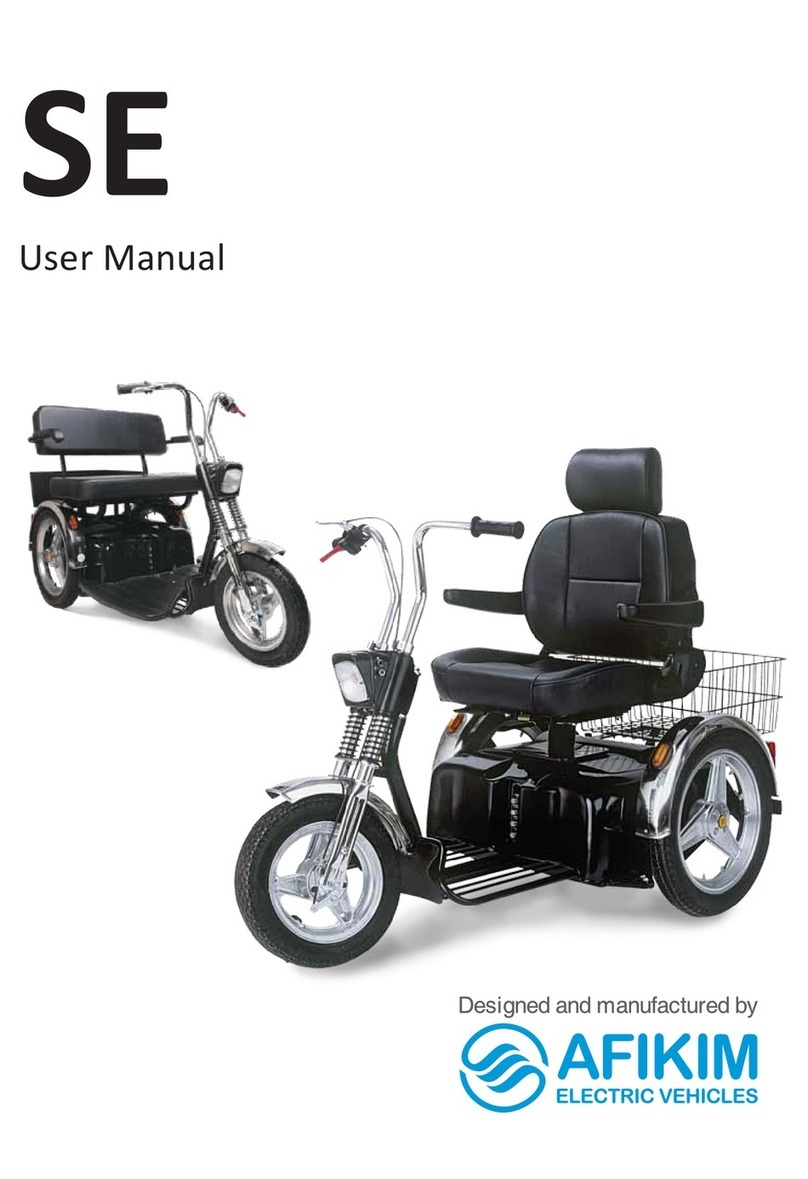
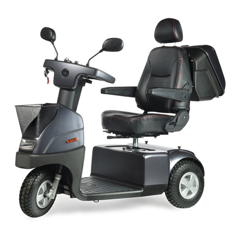
Afikim afiscooter-s User manual

Service Manual AFISCOOTER S v.1.9
Ver. 01
1
Afiscooter s
Service manual

Service Manual AFISCOOTER S v.1.9
Ver. 01
2
Contents
1. Safety instructions 3
2. Specific Tools for technicians 4
3. Specific Parts: 4
4. Options / Accessories assembling drawing /instructions 5
5. Mechanical Adjustments 9
6. Front Electronics Board Setup 10
7. LCD Display Set Up and User Manual 10
8. Controller Programming / Setup 15
9. Controller Parameters List Error! Bookmark not defined.
10. Periodic maintenance Check 21
11. Mechanical Fault troubleshooting 23
12. Control and Electronics system fault troubleshooting 25
12.1 General control system and Front Board Troubleshoots 25
12.2 Trouble Shoot Table: 25
12.3 Controller / Drive Troubleshoots 26
12.4 Controller Fault codes using the LCD: 26
12.5 Controller Trip codes using programmer SP1 & actions to repair: 27
12.6 Possible Faults symptoms and repair actions: 28
13. Mechanical assembly drawings 29
14. Quick guide troubleshoot Afiscooter S electric faults: 29
15. Flow chart for electric trouble shoot: 30
16. Electrical diagrams - General Wiring diagram 35

Service Manual AFISCOOTER S v.1.9
Ver. 01
3
1. Safety instructions
1 General:
1.1.1 Technicians who are servicing the scooter should be authorized to service the scooter.
1.1.2 Technicians who are servicing the scooter should be aware and follow all safety instructions
within the User Manual.
1.1.3 Technician should follow general safety instruction like using gloves, safety glasses when
needed.
1.1.4 The scooter weight with batteries is about 150 kg even lifting 1 wheel is about 40 kg. Always use
other people help or an appropriate lifting device.
1.1.5 When lifting always use your legs and not your back.
1.1.6 The battery weight is about 20-30 kg. The power unit weight is about 25 kg. The seat weight is
about 15kg.
1.1.7 Never do any change in the product before consulting the manufacturer engineering. Remember
the products are approve as they are, any change remove the manufacturer responsibility for the
safety of the product.
2 Drive :
1.2.1 Technicians who are driving the scooter should be aware and follow all safety instructions within
the User Manual.
3 Mechanic :
1.3.1 It is possible that a technician will need to operate the scooter when he is standing on the side,
working on different assemblies.
1.3.2 When no electric power and operation needed, always Stop the power by Switch OFF and
disconnecting the battery terminals.
1.3.3 Never put any part of your body under the scooter parts.
1.3.4 If necessary, first place a wood block under, to make sure no injure will happen.
1.3.5 Use standard tools. Use them according to their safety instructions.
4 Electric :
1.4.1 If necessary to operate the scooter when you are not seating on it. In such cases you should be
aware to the parts that can move by power –Power unit shafts and wheels.
1.4.2 Never put your hands close to a part that is moving or turning. Be aware that your cloth will not
be trapped into one of the moving parts.
1.4.3 Batteries contain a large electric energy inside. This energy can cause sparks and heat metals
when short circuiting.
1.4.4 When working on the battery terminals, make sure no to short circuit between any 2 terminals.
This can cause strong spars and make the tools very hot.
1.4.5 When working on the batteries, use protecting gloves and safety glasses.
1.4.6 Battery contains acid. Never open any of the battery case. If you see any liquid or Gel aside,
beware of it. It might be Acid.
Service Manual AFISCOOTER S v.1.9
Ver. 01
4
2. Specific Tools for technicians
Standard tool box (wrenches, socket-head cap screw, hexagon keys, Phillips (crosshead)
tip and/or screwdrivers, etc.)
Voltmeter (To measure 24VDC)
Air pressure gauge (To measure 35 psi)
Batteries tester (under load)
Density meter
Valve Wrench
P&G SP-1 Programmer (for S-Drive, possible to upgrade old model to modified free of
charge)
Wooden blocks to elevate the Afiscooter during checks, maintenance and repairs:
2 blocks 20-22 centimeters height to place beneath the batteries box.
2 blocks 14-16 centimeters height to place beneath the foot rest area.
Remark : Always before operating a lifted Afiscooter make sure that the 2 rear wheels
are free to turn , so that the scooters will not move.
3. Specific Parts:
We recommend the availability of the following set of test and repair assemblies:
1. Front Board
2. Display LCD Board
3. Main Harnesses Cable.
4. Main Front Lights Harness Cable.
5. Main Rear Lights Harness Cable
6. Motor/Power Unit
7. Rear Light Board LEDs
8. Front Headlight
9. Controller SDrive 140A - P&G
10. Key Switch
11. Charging Socket
12. Main Supply Harnesses.
13. Charger
14. Sensors Harness
15. Handlebars switches –Left and Right
16. Main Fuse & Charging Fuse

Service Manual AFISCOOTER S v.1.9
Ver. 01
5
4. Options / Accessories assembling
1An integrated canopy consisting of a polycarbonate window, a steel frame and plastic covers.
Installation instructions in appendix 1.
2 Rear box for dual seat Rear box for single seat
drawing in appendix 3 drawing in appendix 2
3Seat belt.
Connect to the lower screw of the armrest on both sides.
The location of the belt buckle is between the armrest and the seat.

Service Manual AFISCOOTER S v.1.9
Ver. 01
6
4Connection facilities for walking sticks and crutches.
Rear frame connection device - Seat connection device -
connects to the ears in the rear frame connects to the armrest screws
5 Left hand operation.
6Foot Pedal System.
Assembly instructions
in appendix 4.

Service Manual AFISCOOTER S v.1.9
Ver. 01
7
7Golf wheels.
8Golf wheels fenders.
Assembly by 4 screws
With washers and nuts for each fender.
9Flexible rain cover.
10 Floor raise
Elevation for 3 wheels Elevation for 4 wheels

Service Manual AFISCOOTER S v.1.9
Ver. 01
8
11 Canopy mirror
Assemble the mirror to the bracket according to Fig. 1
Attaching the mirror to the canopy by an existing screw (Fig. 2).
12 Shabbath Kit
Installation Instructions in appendix 5.
Figure 1
Figure 2

Service Manual AFISCOOTER S v.1.9
Ver. 01
9
5. Mechanical Adjustments
#
Description
image
How to Adjust
1
Seat Height
Release both secure bolts (10)
and level bolt (14). Change pin
Level hole as required.
Resecure both level bolt and
secure bolt.
Make sure the seat pin is
parallel to the controller cover.
Adjustments : 3 x 20 mm.
2
Tiller Height
Release the secure nut and
screw, adjust height and
resecure again the screw and
the nut.
Adjustments: 25 mm
1. Lower and middle holes.
2. Second and fourth holes.
3
Rear Shock
absorber Load
Using a C Type key,
adjust the load rate by
changing the Sprint pretention.
Remark: The Adjust should fit
the comfort of the user.

Service Manual AFISCOOTER S v.1.9
Ver. 01
10
6. Front Electronics Board Setup
On the front board there are DIP Switches whose job is to define the
operation of the buzzer in signals and faults.
Can also be adjusted via the controller by changing parameters.
Dip Switches Setup is as follows : (Shown the Default Set Up)
switch
Operation trigger
Default
TGA Default
1
signals
OFF = close
ON = open
2
faults
OFF = close
OFF = close
Default:
TGA Default:

Service Manual AFISCOOTER S v.1.9
Ver. 01
11
7. LCD Display Set Up and User Manual
1. User interfaces
Display information:
Right/Left turn signal: Use to show right/left Blinkers working.
Main light: Use to show Front lights and rear Pilot lights are working.
Digital information: Shows- Speed, Distance of Trip, Time of Trip, Time or Faults Codes.
Speed units: Show mph (miles per hour) or kph (kilometers per hour).
Distance units: Shows- mile (miles) or km (kilometers).
Speed limit: half speed / full speed.
Battery capacity: 10 Bars =full, 1 bar = empty, between is proportional.
Warning: Indicate when error / inhibit mode.
Electromagnet Lever: Indicate when the EMB is opened.
High engine temp: Indicate when the motor is heated.
Overturning danger: In this version, the Overturning danger display will not be activated.
Electromagnet
Lever
Battery
Capacity
Left Turn
Signal
Right Turn
Signal
Warning
Main
Light
Speed
Limit
Digital
Information
Clock
Speed
Units
Distance
Units
Overturning
Danger
(future)
High engine
temp

Service Manual AFISCOOTER S v.1.9
Ver. 01
12
Push buttons:
Right –Mode : Use to change between different display modes and to Reset
the Distance and Time.
Left-Setup : Use to adjust the clock. As well as on and off the display lighting.
Internal LED: Can be seen only from the bottom side of the LCD board. When
LCD board active –flashes to indicate OK, constantly on in charge mode.
2. Speed reading:
This is done with the help of a magnetic sensor located on the right wheel axle.
The speed reading is affected by the wheel diameter - the possibility of choosing
between the wheel diameters in the parameter table.
3. Numeric view:
Three views -
a. Speed (mph / kph). - Resolution - 1kmh / 1mph
b. Distance (miles / km). Resolution - 0.1mile / 0.1km
c. Current time (HH: mm). (The clock will light up)
Switch between modes by pressing the MODE key.
Without automatic switching to default mode.
4. User view:
4.1 Backlight:
The backlight has two activity levels, which are determined by the user
settings.
- Night Light Level - When the headlight signal is active.
LCD

Service Manual AFISCOOTER S v.1.9
Ver. 01
13
- Daylight level - When the headlight signal is inactive.
A short press on Setup turns off and on the backlight.
4.2 View information:
Switching between the different types of information is done by pressing with
the Mode key.
1. Hour in 24 hours / 12 hours format (can be changed in settings mode), long
press on SETUP for 3 seconds (only minute and hour, no day and date,
time according to time format). The clock indicator will light in this mode.
2. Travel speed in km / mile per hour (can be changed in settings mode),
according to the reading from a speed sensor only.
3. Travel range in km / miles with reset option (press SETUP for 3 seconds).
• When the tool is turned on and off, the screen will always return to the last
state it was in before turning off.
4.3 Settings:
Long press for 7 seconds on MODE and SETUP will put the screen in the
settings mode. In this mode it will be possible to scroll between the various
parameters using the SETUP button, pressing MODE will change the value of
the displayed parameter. A parameter will appear as follows: P XX, where XX
represents the parameter number. The last mode will be a reset mode that will
look like this: Cr. turning the tool (and the screen) on and off will cause the
settings screen to exit and return to the previous state the user was in. After
entering a particular parameter, MODE switches between the different values
of the displayed parameter, SETUP switches between the various
parameters.
OPTIONS
DESCRIPTION
PARAMETER
1- kilometer, km / h (default)
2- miles, miles per hour
Distance and
speed display
P 01
1- Celsius (default)
2- Fahrenheit
Temperature
display
P 02
1 - 310 - Not used in this model
2 - 410 - Golf wheel
3 - 430 - Standard Wheel (Default)
Wheel diameter
P 03
1 - 24 hours (default)
Hour display
P 04

Service Manual AFISCOOTER S v.1.9
Ver. 01
14
4.4 Fault display:
When there is a fault the comment pops up on the screen.
Fault table on page 24 Section 12.4
In a situation that the potentiometer is pressed when turn on the scooter, a
signal c will appear in the status line. When this condition is detected, the last
condition of the batteries must be displayed before the shutdown, until the
potentiometer is released and returned to normal operation. The numeric
display will show a running animation of the digit '0' from left to right on all five
digits in the display in a cyclic manner, 120mSec per digit until the
potentiometer is released and beyond signal a. This animation will be
displayed in both modes of parameter 7.
5. Display the software version burned on the LCD:
Activating the tool using the key switch, when the Mode button is pressed, will
display the software version number for about 3 seconds, and then switch to normal
working mode.
2 - 12 hours
0- Off.
1-5 - Scale of Power.
(Default - 5)
Daytime running
backlight
(headlight off)
P 05
0- Off.
1-5 - Scale of Power.
(Default - 2)
Night running
backlight
(headlight on)
P 06
1- From the S-Drive status line. (Default)
2- According to a calculation from the
algorithm in the card.
Battery display
from the status
line / algorithm on
the board.
P 07
1 - Fault code is displayed in
alphanumeric view (default).
2 - Fault code is displayed in the
exclamation mark (flashing).
Status indicator
P 08
Reset the parameters to default.
Reset the display
parameters
Cr

Service Manual AFISCOOTER S v.1.9
Ver. 01
15
8. Controller Programming And A List Of Programming Parameters
8.1 General
The scooter behavior while driving can be adjusted by programming the controller, for
example slowing down, changing the direction of operation of the operating handle and
more. Only a qualified technician may change the controller programming.
Warning: Bad programming of the controller can cause safety problems in the behavior
of the scooter.
The following parameters refer to the s-drive 140 controller with sp1a manual
programming.
Programming can be done through the charging socket with an adapter or directly to the
programming socket in the controller without an adapter.
Note: You can also purchase a PC programming system.
Charger Socket Adapter P/N - ASS4079 Programmer sp1a P/N - PCS4002
Note: In case of any need to change a parameter that is not highlighted in the list, please contact
and consult with Afikim Electric Vehicle Engineering.
8.2 Operating Instructions
8.2.1 Connect the adapter to the programmer and plug into a charging socket (the
programmer starts working).
8.2.2 The up and down arrows (↑) (↓) allow the parameter to be selected.
8.2.3 To change a parameter, see the parameter in the display bar and press the "ENTER"
button, then the value of this parameter appears.
8.2.4 Using the arrows (↑) (↓) you can increase or decrease the value. (In some cases a
change between Off and On).
8.2.5 After setting the new value press the "ENTER" button, the scooter buzzer will beep
several times (in this situation the scooter will not travel).
8.2.6 The key switch must be closed and activated in order to return the scooter to normal
operation. (Some parameters value is determined in pairs).
8.2.7 Programmer returns to the list of parameters. To change another parameter repeat
the previous 3 sections
8.2.8 In the engineering menu bar enter the change of engineering parameters.

Service Manual AFISCOOTER S v.1.9
Ver. 01
16
8.3 List of parameters for S-Drive140 controller with power unit model CT10 / CT12 / CT15
8.3.1 Parameters for use in manual programmer:
Note:
Highlighted parameters - User customizable values can be downloaded.
Any change in parameters that are not highlighted - it is recommended to consult
the manufacturer.
#
Parameter name
Parameter
text
units
CT10
CT12
CT15
Explanation of the parameter
1
Forward Accel'n ?
fast
0.1s
35
40
40
Acceleration forward fast
1
Forward Accel'n ?
slow
0.1s
40
50
50
Acceleration forward slow
2
Forward Decel'n ?
fast
0.1s
14
15
14
Deceleration forward fast
2
Forward Decel'n ?
slow
0.1s
12
13
20
Deceleration forward slow
3
Reverse Accel'n ?
fast
0.1s
40
40
25
Acceleration backward fast
3
Reverse Accel'n ?
slow
0.1s
40
40
60
Acceleration backward slow
4
Reverse Decel'n ?
fast
0.1s
15
15
17
Deceleration backward fast
4
Reverse Decel'n ?
slow
0.1s
15
15
14
Deceleration backward slow
5
Max Fwd Speed ?
fast
%
100
100
100
Max forward speed fast
5
Max Fwd Speed ?
slow
%
60
60
50
Max forward speed slow
6
Min Fwd Speed ?
fast
%
50
50
30
Min forward speed fast
6
Min Fwd Speed ?
slow
%
30
30
30
Min forward speed slow
7
Max Rev Speed ?
fast
%
50
50
40
Max backward speed fast
7
Max Rev Speed ?
slow
%
35
35
30
Max backward speed slow
8
Min Rev Speed ?
fast
%
30
30
30
Min backward speed fast
8
Min Rev Speed ?
slow
%
30
30
30
Min backward speed slow
9
Invert Throttle?
inv throttle
No
No
No
Invert potentiometer
10
Sleep Timer ?
time
m
0
0
0
Sleep mode
11
Read System
Log?
Reading Fault History
12
Read Timer?
elapsed
h
Reading a working hours counter
13
Engineer Menu ?
Enter the engineering menu (from
here to the end)
14
Current Limit ?
min
A
130
130
130
Min. Current limitation
15
Current Limit ?
max
A
130
130
130
Max current limitation
16
Output Voltage?
output
V
24
24
24
Output voltage
17
Drive Boost ?
current
A
140
140
140
Boost current
18
Drive Boost ?
time
s
10
10
10
Boost current time
19
Drive Foldb'k 1 ?
threshold
A
110
110
110
Driver fold back current
20
Drive Foldb'k 1 ?
time
s
30
30
30
Driver fold back time
21
Drive Foldb'k 2 ?
level
%
70
70
70
Driver fold back level
22
Drive Foldb'k 2 ?
temp
ºC
80
80
80
Driver fold back temperature
23
Motor Cooling ?
time
s
120
120
120
Cool time
24
Compansation ?
motor cmp
mΩ
20
20
20
Speed compensation - resistance of
the armature

Service Manual AFISCOOTER S v.1.9
Ver. 01
17
25
Parameter 3?
Param. 3
130
130
130
Parameter 3 - Value-enhanced
engine compensation
26
Parameter 4?
Param. 4
30
30
30
Parameter 4-Boost Delay
27
Bridge Hold?
bridge hld
cs
300
115
140
Bridge hold
28
Soft Stop ?
soft-stop
On
On
On
Soft Stop
29
Freewheel?
threshold
100
100
100
Freewheel - hold
30
Freewheel?
timeout
cs
20
20
20
Freewheel - time
31
Throttle Gain ?
gain
170
160
160
Potentiometer - gain
32
Throttle D'band ?
deadband
%
9
9
9
Potentiometer –dead band
33
ISO Tests ?
ISO tests
Off
Off
Off
ISO tests
34
Throttle Type ?
thrtl' type
2
2
2
Potentiometer type
35
Displaced Mode?
Dspl mode
1
1
1
Starting with potentiometer in
position not "0"
36
Check Refs?
check refs
Yes
Yes
Yes
Potentiometer test
37
Speed Limit Pot?
pot
enabled
No
No
No
Speed limit potentiometer
38
Brake Time ?
brake time
ms
650
750
1000
Electromagnetic brake -activation time
39
Brake Check?
brake
check
Yes
Yes
Yes
Electromagnetic brake - Integrity check
40
Brake Alarm?
brake
alarm
Yes
Yes
Yes
Electromagnetic brake -
Disconnection alarm
41
Brake Light?
brake light
No
No
No
Activating braking light
42
Status Output?
type
0
0
0
Set status port for display
43
Diagnostic Flash
flesh
2
2
2
Setting up troubleshooting the display
44
Diagnostic Alarm
diag. alarm
Yes
Yes
Yes
Activating a buzzer during faults
45
Inhibit 1 Mode?
Mode
1
1
1
Set mode inhibit No. 1
46
Inhibit 1 Speed?
speed
0
0
0
Set speed inhibit No. 1
47
Inhibit 1 Latch?
latched
No
No
No
Need to restart after inhibit No. 1
48
Inhibit 2 Mode?
Mode
1
1
1
Set mode inhibit No. 2
49
Inhibit 2 Speed?
speed
0
0
0
Set speed inhibit No. 2
50
Inhibit 2 Latch?
latched
Yes
Yes
Yes
Need to restart after inhibit No. 2
51
Inhibit 3 Mode?
Mode
1
1
1
Set mode inhibit No. 3
52
Inhibit 3 Speed?
speed
0
0
0
Set speed inhibit No. 3
53
Inhibit 3 Latch?
latched
No
No
No
Need to restart after inhibit No. 3
54
Clear SystemLog
erase log
Clearing fault history
55
Clear Timer
clear timer
Reset counter working hours
56
Reverse Alarm?
Alarm
Off
Off
Off
Buzzer is activated when driving
backwards
57
Pulse Rev Alarm?
pulsed
Yes
Yes
Yes
Reverse buzzer with breaks (pulses)
58
TruCharge Cable?
cable res
mΩ
60
60
60
Cable resistance for batteries
59
TruCharge Cal.?
calibration
%
100
100
100
Calibration of battery status
60
Low Batt Flash ?
flash level
2
2
2
Low battery signal on display
61
Low Batt Alarm?
Low bat.
alm
Off
Off
Off
Low battery alarm
62
Back To Root ?
Back to main menu

Service Manual AFISCOOTER S v.1.9
Ver. 01
18
8.3.2 Parameters for using PC software:
PC programmer
Software rev. 14.6.0
Power Unit
Parameters
CT10
CT12
CT15
Explanation of the
parameter
Speed Settings
Forward Acceleration Fast Profile (0.1 Sec)
35
40
40
Acceleration forward fast
Forward Acceleration Slow Profile (0.1 Sec)
40
50
50
Acceleration forward slow
Forward Deceleration Fast Profile (0.1 Sec)
14
15
14
Deceleration forward fast
Forward Deceleration Slow Profile (0.1 Sec)
12
13
20
Deceleration forward slow
Reverse Acceleration Fast Profile (0.1 Sec)
40
40
25
Acceleration backward fast
Reverse Acceleration Slow Profile (0.1 Sec)
40
40
60
Acceleration backward slow
Reverse Deceleration Fast Profile (0.1 Sec)
15
15
17
Deceleration backward fast
Reverse Deceleration Slow Profile (0.1 Sec)
15
15
14
Deceleration backward slow
Max Forward Speed Fast Profile (%)
100
100
100
Max forward speed fast
Max Forward Speed Slow Profile (%)
60
60
50
Max forward speed slow
Min Forward Speed Fast Profile (%)
50
50
30
Min forward speed fast
Min Forward speed Slow Profile (%)
30
30
30
Min forward speed slow
Max Reverse Speed Fast Profile (%)
50
50
40
Max backward speed fast
Max Reverse Speed Slow Profile (%)
35
35
30
Max backward speed slow
Min Reverse Speed Fast Profile (%)
30
30
30
Min backward speed fast
Min Reverse Speed Slow Profile (%)
30
30
30
Min backward speed slow
Speed Limit Pot Enabled
Off
Off
Off
Speed limit potentiometer
Operation Settings
Sleep Timer (Minutes)
0
0
0
Sleep mode
Throttle Invert
No
No
No
Invert potentiometer
Battery Settings
Low Battery Flash Level (Bars)
2
2
2
Low battery signal on display
Cable Resistance (milli-Ohms)
60
60
60
Cable resistance for batteries
Calibration Factor
100
100
100
Calibration of battery status
Low Battery Alarm
Off
Off
Off
Low battery alarm
Trucharge Reset Voltage Tag
255
255
255
Reset voltage reads batteries
Battery Curve Scaler
0
0
0
Battery status curve - multiplier
Low Voltage Cut-Out (Deci-Volts)
160
160
160
Low Voltage Cut-Out Time (Secs)
255
255
255
Inhibit Settings
Inhibit 1 Mode
1
1
1
Set mode inhibit No. 1
Inhibit 1 Operation
Non-
Latching
Non-
Latching
Non-
Latching
Need to restart after inhibit No. 1
Inhibit 1 Speed (%)
0
0
0
Set speed inhibit No. 1
Inhibit Mode 2
1
1
1
Set mode inhibit No. 2

Service Manual AFISCOOTER S v.1.9
Ver. 01
19
Inhibit 2 Operation
Latching
Latching
Latching
Need to restart after inhibit No. 2
Inhibit 2 Speed (%)
0
0
0
Set speed inhibit No. 2
Inhibt Mode 3
1
1
1
Set mode inhibit No. 3
Inhibit 3 Operation
Non-
Latching
Non-
Latching
Non-
Latching
Need to restart after inhibit No. 3
Inhibit 3 Speed (%)
0
0
0
Set speed inhibit No. 3
Aux Output Mode
2
2
2
Set Aux output
Inhibit 2 Aux Output
2
2
2
General Settings
Soft Stop
On
On
On
Soft stop
Brake Drive Time (mili-Sec)
650
750
1000
Electromagnetic brake -activation
time
Output Voltage (Volts)
24
24
24
Output voltage
Status Output Type
0
0
0
Set status port for display
Diagnostic Flash Sequence
2
2
2
Setting up troubleshooting the
display
Reverse Alarm
Off
Off
Off
Buzzer is activated when driving
backwards
Reverse Alarm Tone
0
0
0
Set reverse alarm tone
Pulsed Reverse Alarm
On
On
On
Reverse buzzer with breaks
(pulses)
Diagnostic Alarm
On
On
On
Activating a buzzer during faults
Diagnostic Alarm Tone
0
0
0
Set buzzer during faults tone
Brake Disconnected Alarm
On
On
On
Electromagnetic brake -
Disconnection alarm
Brake Disconnected Alarm Tone
0
0
0
Set Electromagnetic brake -
Disconnection alarm tone
Brake Fault Detect
On
On
On
Electromagnetic brake - Integrity
check
Brake Light
Off
Off
Off
Activating braking light
Push too Fast threshold
100
100
100
Freewheel - hold
Push too Fast Timeout (0.01 Sec)
20
20
20
Freewheel - time
Freewheel Enable
Enable
Enable
Enable
Activate freewheel mode control
Inhibit 2 Horn Input Enable
Off
Off
Off
Inhibit buzzer input
Horn Tone
0
0
0
Set buzzer tone
Thermal Shutdown Trip
No
No
No
Motor Settings
Current Limit Max (Amps)
130
130
130
Max current limitation
Boost Drive Current (Amps)
140
140
140
Boost current
Boost Drive Time (Sec)
10
10
10
Boost current time
Current Foldback Threshold (Amps)
110
110
110
Driver fold back current
Current Foldback Time (Sec)
30
30
30
Driver fold back time
Current Foldback Level (%)
70
70
70
Driver fold back level

Service Manual AFISCOOTER S v.1.9
Ver. 01
20
Motor Cooling Time (Sec)
120
120
120
Cool time
Current Foldback Temp (Deg C)
80
80
80
Driver fold back temperature
Current Limit Min (Amps)
130
130
130
Min. Current limitation
Motor Stall Timeout (Sec)
0
0
0
Motor Compensation (milli-Ohms)
20
20
20
Speed compensation - resistance
of the armature
Anti-Rollback Level
0
12
0
Anti-Rollback Level
Pull-away Delay (centi-Sec)
30
30
30
Parameter 4-Boost Delay
Slope Factor
500
500
500
Slope Factor
Anti-Rollback Velocity
42
0
28
Anti-Rollback Velocity
Braking Current Limit (Amps)
140
140
140
Braking Current Limit
Timed Foldback Braking Current (Amps)
130
130
130
Braking Current fold back time
Timed Foldback Speed (%)
100
100
100
Braking Current fold back speed
Enhanced Motor Compensation (Up)
130
130
130
Parameter 3 - Value-enhanced
engine compensation
Enhanced Motor Compensation (Down)
300
115
140
Bridge hold
Enhanced Motor Compensation (Up) Gain
1
1
1
Throttle Settings
Manufacturer settings only
Throttle Type
2
2
2
Potentiometer type
Throttle Deadband (%)
9
9
9
Potentiometer –dead band
Throttle Gain (%)
170
160
160
Potentiometer - gain
Throttle Operated at Power-Up
1
1
1
Starting with potentiometer in
position not "0"
Throttle Reference Test
On
On
On
Potentiometer test
ISO Test Resistor
Off
Off
Off
ISO tests
Timed Throttle Invert
0
0
0
Other manuals for afiscooter-s
1
Table of contents
Other Afikim Scooter manuals

Afikim
Afikim afiscooter-s User manual

Afikim
Afikim BreezeIV User manual

Afikim
Afikim SPORTSTER SE User manual

Afikim
Afikim Breeze S3 User manual

Afikim
Afikim Caddy User manual

Afikim
Afikim Superlight SL-3 User manual

Afikim
Afikim SE User manual

Afikim
Afikim Breeze C3 User manual

Afikim
Afikim Afiscooter-M User manual

Afikim
Afikim Breeze-C User manual
Popular Scooter manuals by other brands

Pride Mobility
Pride Mobility scooter owner's manual

Dynacraft
Dynacraft MONSTER HIGH owner's manual

Authentic Sports & Toys
Authentic Sports & Toys SIX DEGREES Stuntscooter owner's manual

Juiced Bikes
Juiced Bikes SCORPION 2021 owner's manual

RA
RA GP125i Maintenance manual

KYMCO
KYMCO 50 VITALITY 2T Specifications