Afikim Superlight SL-3 User manual


________________________________________________________2
WARNING
Read the User’s Manual carefully before operating the Superlight.
If you do not fully understand any part of this Manual,
Please contact your dealer or any of our Service.
Read this manual step by step
Centers - as injury or damage may occur from misuse!
WARNING
Electromagnetic Interference (“EMI”) can cause powered vehicles
to behave erratically, which could be dangerous to the user.
For your safety and protection, it is IMPERATIVE that you take
time to read Chapter : "EMI WARNING” before operating the
Superlight .
Serial Number Label is affixed to the Tiller: See Fig 10.
CE CERTIFICATION
The Afikim Electric Vehicles Ref. Registration Number with the
Competent Authority (UK)
is: CA 000292.
Our Authorized Representative with the
Competent Authorities is:
MEDES LTD.POB 231
Stanmore, Middlesex, HA7 4YA, England
TEL/FAX: 0044-181-954-9964
EDITION: 02
MODEL: SL-3
DATE: July 28, 2004
Cat. No. – PRSL001
I:\SL-3\WORD FILES\user manual sl3\User Manual SL3-ver5.DOC

________________________________________________________3
CONTENTS
Subject Page
CHAPTER 1 - DELIVERY and UNPACKING ........................................ 3
CHAPTER 2 - ASSEMBLY..................................................................5
CHAPTER 3 - OPERATING INSTRUCTIONS ................................... 12
CHAPTER 4 - DISASSEMBLY...........................................................16
CHAPTER 5 - CHARGING BATTERIES............................................. 19
CHAPTER 6 - STORING IN CAR........................................................21
CHAPTER 7 - TROUBLESHOOTING................................................22
BATTERY CHARGER - TROUBLESHOOTING..................................23
CHAPTER 8 - SAFETY INSTRUCTIONS ......................................... 24
CHAPTER 9 - SERVICE..................................................................... 26
CHAPTER 10 - SPECIFICATIONS *..................................................28
CHAPTER 11 - EMI WARNING.......................................................... 30

________________________________________________________4
CHAPTER 1 - DELIVERY and UNPACKING
The SUPERLIGHT Scooter is delivered to you
packed in one Cardboard Box. .
Note: The box weight 60kg (132 lb.) - do NOT attempt to
lift it with out assistance.
1.1 Unpack as follows (See Fig. 1)
a. Place boxes on floor with side up as marked by
the arrows on the side of the box.
b. Cut the Plastic Bands.
c. Remove the cardboard Top Cover.
d. Remove all parts from the boxes (and lay on the floor)
e. Identifying the SUPERLIGHT Components (See Fig. 1)
(1) Batteries Cover (2) Frame
(3) Seat (4) Batteries (left & right)
(5) Charger (6) Seat Adapter
(7) Tiller (8) Rear Basket
(9) Power Unit
Figure 1

________________________________________________________5
CHAPTER 2 - ASSEMBLY
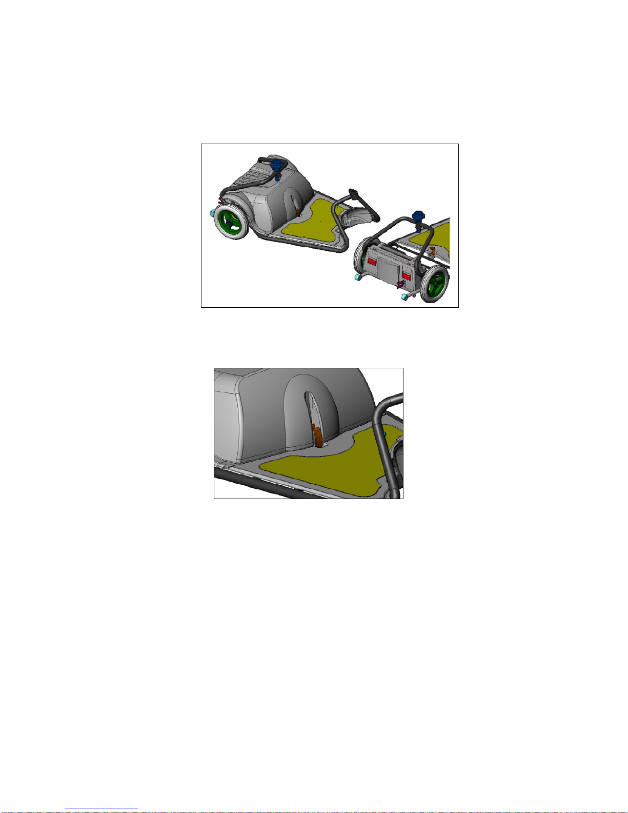
2.1 Installation of the Power Unit
a. Position the Superlight power Unit on the floor so that the
anti tip is backward direction.
b. Lay the frame at the front of the power unit (See figure 2)
c. Lift the frame and install the frame bracket onto to power
unit square connecting bracket. Make sure the frame is
down to the end of the bracket. (See figure 3)
figure 2 figure 3
d. Secure the frame to the power unit by the anti tip securing
arrangement. Do that by releasing the knob at the right of
anti tip and pulling it upward until the knob is re secured.
(See figure 4)
figure 4 figure 4a

________________________________________________________6
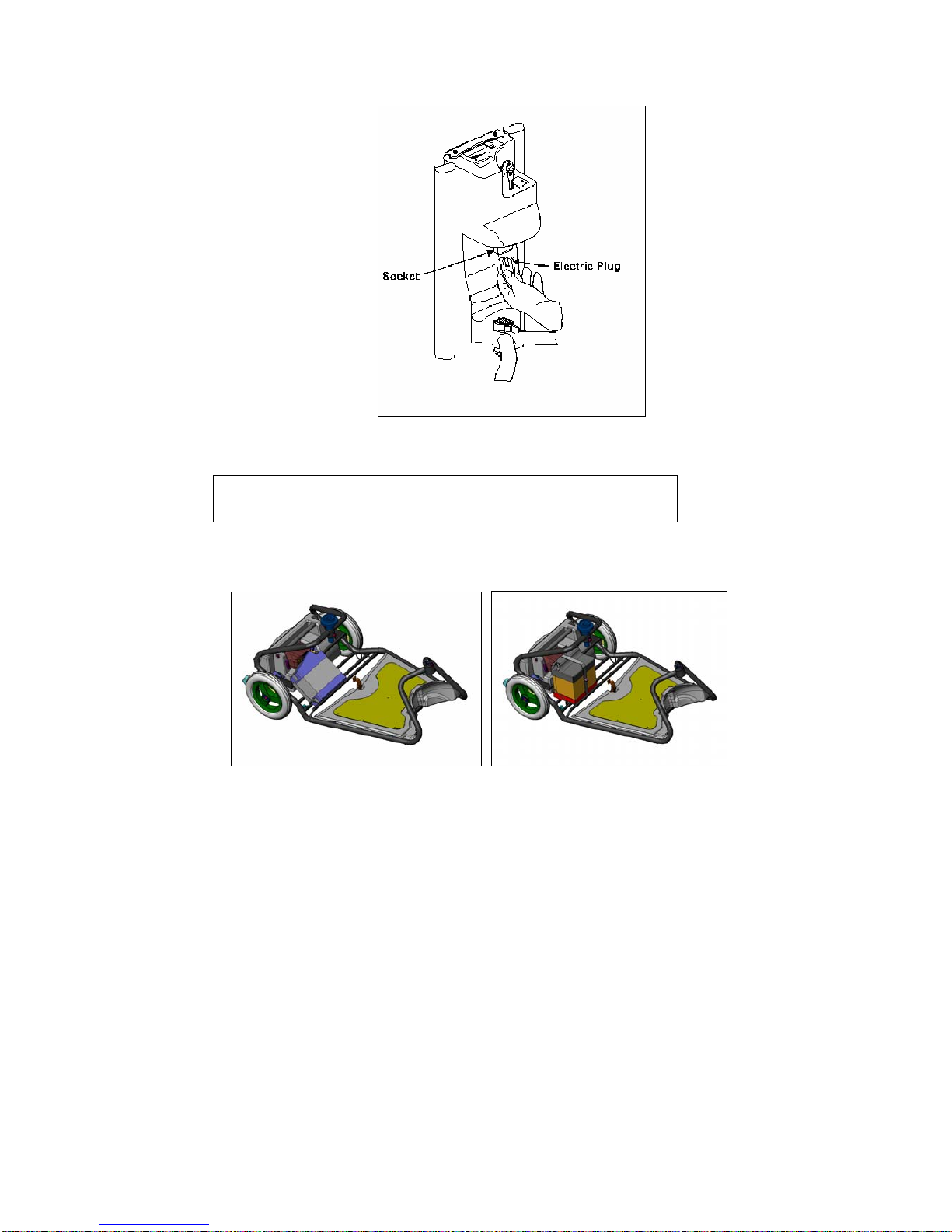
e. To assure that the power unit is properly connected to the
frame ,you can try and lift the frame.
f. Connect the electrical connector coming from the frame to
the power unit Socket (See figure 4a) .
WARNING
After installing the frame onto the power unit and
locking it, Please check carefully that it is properly
positioned and secured.
2.2 Joining Tiller to Frame.
a. Place Tiller in front of the Frame. (See Fig. 5).
Kneel at the left side of the SUPERLIGHT holding the
left side of the Top Handle Bars of the Tiller with your
left hand. The Tiller should be vertical and slightly
inclined backward as shown in Figure 5.
b. With your right hand lift the Housing (at the front end of
the Frame) and place it above the (black) Tapered Pin
mounted on the Tiller.
c. Let the Housing slide down onto the black Tapered Pin
until you hear a “click”: at this time the Retaining Spring
should engage the Groove on the Tapered Pin thus
locking both sections to each other.
Figure 5

________________________________________________________7
d. Connect the Electric Plug to the Socket in the
Tiller (See Figure 6).
figure 6
2.3 Installation of Batteries (See Fig. 7)
Note: Installation of L.H Battery is identical to R.H.
Battery. L.H. Battery is shown.
a. Place battery in its location on the frame.
b. Connect Battery Plugs to battery.
Figure 7 – Small Battery Figure 8 – Large Battery

________________________________________________________8
2.4 Installation of Batteries Cover (See Fig. 9)
a. Place Batteries Cover over the Batteries .
Make sure to insert the rear plates under the
cover into the slots in the power unit and that the
front of the cover seat properly.
(See Figure 9)
Figure 9
c. Push the Plastic Clip to secure the Batteries
Cover in its location (See Figure 10).
Figure 10

________________________________________________________9
2.5 Seat Installation (Figure 11)
Seat Installation and Adjust:
a. Insert the Seat Adapter into the Seat-Bushing
(1) Verify that the Seat-Bushing slot is in forward direction.
(2) Install bolt and washer and tighten the bolts very well,
using the attached wrench.
(3) Install and tighten the securing nut very well, using attached
wrench.
(4) Install the Seat into the Seat-Bushing while the Seat is 45
degree to the side of the frame.
(5) Press the Seat Turning Lever to place the Seat forward
position.
b. Adjusting the height of the Seat
Remove nut,
bolt and washer.
Change the
Seat Adapter
height,
install, bolt and
washer and
tight strongly
the securing nut.
c. Install Seat
Upholstery.
Figure 11

________________________________________________________10
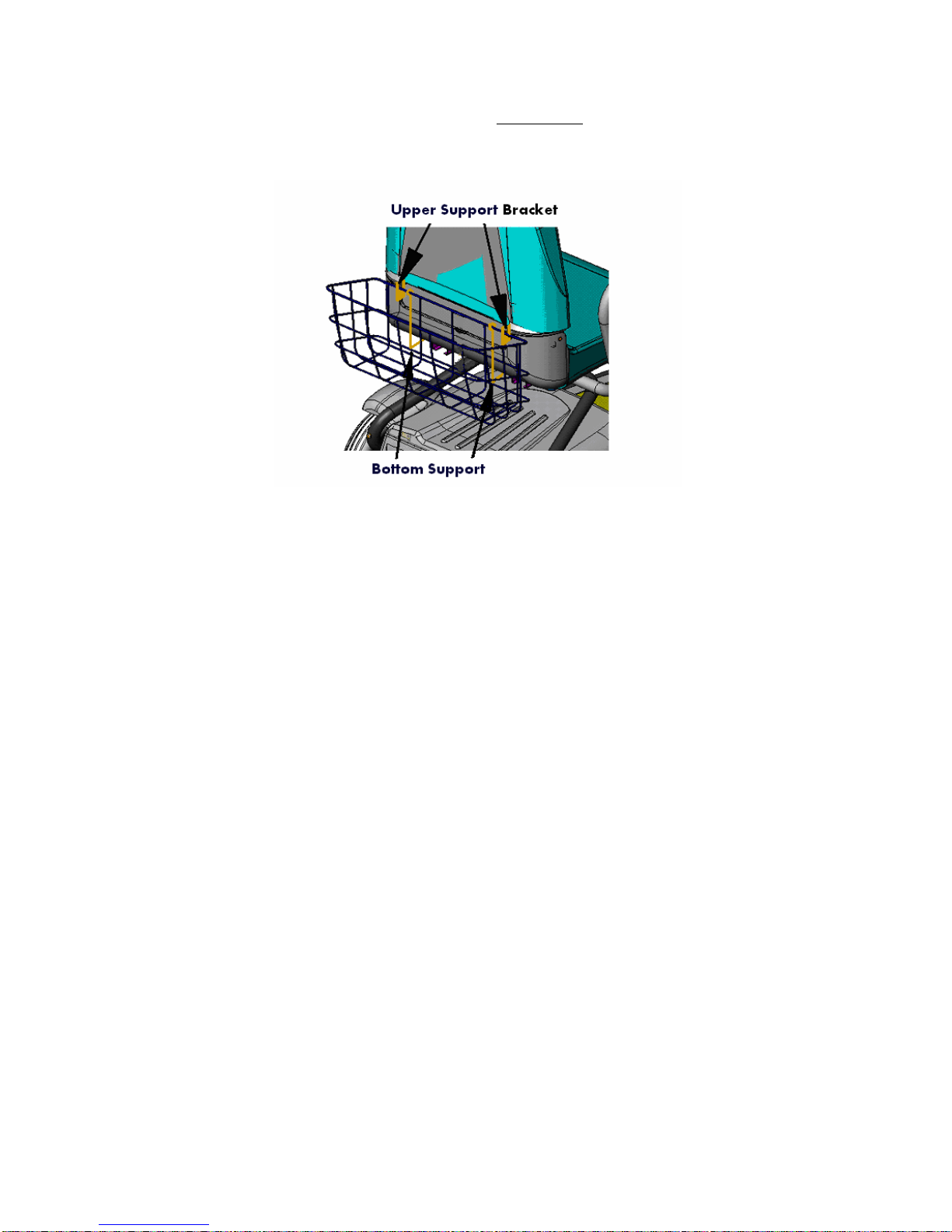
2.6 Rear Basket Installation
a. Install the Rear Basket by placing it on the two Upper
Support bracket at the rear of the seat back lying on
the Bottom Support. (See Fig. 12).
Figure 12
2.7 After the assembly make sure that:
a. All parts are undamaged, properly assembled
and secured.
b. All electrical plugs are properly fastened.
c. The operating levers return automatically to
center position when they are squeezed and
released.
It is recommended to charge the batteries overnight before
operating the SUPERLIGHT for the first time. See Chapter 5
for charging instructions.

________________________________________________________11
2.8 Seating into the SUPERLIGHT
a. For comfort entering into the SUPERLIGHT
(See Figure 13).
b. Lift the Seat Turning Lever and turn the Seat
45 or 90 degree to the side of the frame.
c. Sit down and turn swivel back towards the front
of the vehicle while the lever is still pulled up.
d. Use the Seat Slider Lever to adjust the Seat
forward/Backward (See Fig. 13).
e. Fold the Seat Armrest as desired while getting
in or out of the vehicle.
Note: For your safety, always keep the armrest closed:
Forward – Down while seated.
Figure 13

________________________________________________________12
CHAPTER 3 - OPERATING INSTRUCTIONS
PLEASE READ THOROUGHLY CHAPTER 8 - “SAFETY
INSTRUCTIONS” - BEFORE DRIVING THE SUPERLIGHT.
Please charge your battery before first use (ca. 6 hours)
3.1 Mount the SUPERLIGHT,insert the Key into the Slot and turn
it clockwise to the (marked) ON position. The Key will remain
in this position. Panel On Light should come ON.(See
Figure 14).
3.2 You can drive forward by gently squeezing the Right Hand
Operating Lever. You can drive reverse by gently squeezing
the Left Hand Operating Lever.
The speed of the SUPERLIGHT is proportional to the
deflection of the Levers; the more you squeeze the
faster you go (either direction).
3.3 TO STOP : Release the Lever - it returns automatically to its
center (neutral) position and the SUPERLIGHT stops.
Note:For your safety and comfort the following features are
part of the normal operating sequence;
- Slight delay after you squeeze the Lever before the motor
is engaged-
- When squeezing or releasing the Lever you should hear a
“click” indicating that the Electromagnetic Brake is
activated.
3.4 The SUPERLIGHT has 2 speed modes ; Low / High
a. In the High speed mode (marked by the “hare” symbol next to
the Speed Selector switch) the maximum attainable speed is
7.5 km/h (4.6 mph) When selector is in High Speed Mode –
Green light of switch is ON. (See Fig. 11).
b. In the Low speed mode (marked by the “turtle” symbol next to
the Speed Selector switch ) the maximum attainable speed is
4.5 km/h (2.8 mph).*
*When selector is in Low Speed Mode – Green light of switch
is OFF. (See Fig. 15).

________________________________________________________13
figure 14 figure 15
3.5 Set the Speed Selector switch as desired.
3.6 When “extra-power” is needed (i.e., climbing allowed slopes)
use the High speed mode.
3.8 Battery Capacity Indicator (See Fig. 15)
The Battery Capacity Indicator is part of the Display Panel. The
indicator contains 4 red leds.
The battery capacity is proportional to the numbers of the
illuminated red leds. (Not include the green ON led).
Thus 4 Illuminated leds means: 100%-80% capacity.
Thus 3 Illuminated leds means: 80%-60% capacity
Thus 2 Illuminated leds means: 60%-40% capacity
Thus 1 Illuminated leds means: 40%-20% capacity
Thus 1 leds flashing means: 20%- 0% capacity

________________________________________________________14
3.7 Lights Operating (See Fig. 16)
To switch on the SUPERLIGHT light, use the Right-Blue switch.
WARNING
1. Until you get used to the SUPERLIGHT and its operational
features - Speed Selector switch should be set at the Low
mode (“Turtle”).
2. When going down hill always use the low speed mode.
Notes:
1. The Battery Capacity Indicator reset itself to full (4
leds) only after full recharge.
2. In case that Charging Adapter is used to charge the
Batteries out of the SUPERLIGHT, the Battery
Capacity Indicator of the vehicle will not reset
automatically.
To reset the Battery Capacity Indicator
Turn on the key switch and wait for 2 minutes
without driving.
Notes:1. There is available a model of SUPERLIGHT in which
the maximum speed is 6.0 km/h .
2. Speed can be limited by authorized technician.
Note: It is recommended to charge the batteries at the end of
each day.

________________________________________________________15
Figure 16
3.9 In case of power fail, low battery or other fail
The SUPERLIGHT can be pushed manually pulling upward the
EMB manual release lever at the rear of the SUPERLIGHT
(See Fig. 17) and pushing the SUPERLIGHT by hand.
The SUPERLIGHT will not operate and the buzzer will beep
until the manual release lever is pushed downward again, back
to its original position.
(The buzzer will operate only when the key switch is in “ON”
position).
figure 17
Charging
Fuse

________________________________________________________16
CHAPTER 4 - DISASSEMBLY
4.1 Removal of Seat (See Fig. 18)
a. Remove the Rear Basket by lifting it up from its
Support Rod.
b. Remove the Seat from the Seat Adapter by
lifting the Seat straight up while turning Release
Lever is pulled only when the Seat is 45ºback
direction to the left.
figure 18 figure 19
4.2 Separation of Tiller from Frame (See Fig. 19).
For ease of operation we recommend working on the left side
of the SUPERLIGHT (facing forward ):
a. Disengage the Electric Plug from its socket in the Tiller by
squeezing the Snap Button (located on the plug) - and pull.
b. Support the Tiller with your left hand holding the Upper Left
Rail.
c. Push the Retaining Spring with the thumb of the right hand
until it is freed from the Groove on the (black) Tapered Pin.
d. Carefully lift the Frame off the Tapered Pin and lay both
sections on the floor.

________________________________________________________17
4.3 Removal of Batteries
Batteries can be easily removed from your
SUPERLIGHT as follows -
a. Remove Seat and Rear Basket (see
instructions in paragraph 4.2 above).
b. Open Batteries Cover - (See Fig. 20).
1) Pull back Plastic Clip
2) Push the cover backward than up a little from
the rear slots in the power unit cover and than
forward out .
c. Disconnect cables from batteries: unplug
Battery Plugs.
d. Remove each battery by pulling it with it's handle .
(See Figure 21).
Figure 20 Figure 21
WARNING !!
Failure to follow above instructions could cause
pinching of your hand or fingers if battery slides down
and causes hand to come in contact with other parts.

________________________________________________________18
4.4 Removal of Power Unit
a. Remove the Batteries. (As explained in 4.3).
b. Disconnect the electrical connector coming from the frame to
the power unit Socket (See Figure 22)
Figure 22 Figure 22a
c. Squeeze the rear knob at the right of the anti tip and pushed it
downward until locked again. (See Figure 22a)
d. Pull up the frame from the square bracket of the power unit
and lay it on the side (See Figure 23).
e. Now you can pick
up the power unit .
Figure 23
WARNING
The power unit weight approximately 14Kg (31 lbs)
Lift it only by loading your Knees .
Never lift it while loading your back

________________________________________________________19
CHAPTER 5 - CHARGING BATTERIES
The Battery Charger supplied with your SUPERLIGHT controls
the charging operation, prevents over-charging and prolongs the
life of the batteries.
Read chargers instructions carefully before using the charger.
Note: There is no ON/OFF power switch to the charger.
5.1 Charging Batteries (See Fig. 24)
a. Insert the Charging Plug into the Charging Socket in the right
hand side of the Tiller of the SUPERLIGHT.
b. Plug the power cord of the Charger into a wall outlet.
c. The Charger Lamp will show as follows:
Red – Charger Cord is plugged into the wall outlet.
Yellow – Charging
Green – Battery are fully charged .
When charging is complete and you are ready to go -unplug the
Charger from the wall outlet and then pull out the charging
plugfrom the charging socket.
Figure 24
d. Under ideal storage conditions, batteries which were charged to
full capacity and not used -will remain charged for approximately
6 months.

________________________________________________________20
e. If you are planning not to use your SUPERLIGHT for an
extended period of time, we recommend charging it for two days
and then disconnecting the batteries.
f. If you have not used your SUPERLIGHT for an extended period
of time, charge the batteries for at least 12 hours before driving.
•
There is NO need to disconnect the Charging Plug promptly
after the charging is complete.
•
HOWEVER, do not leave the Charger connected to the
batteries for more than two weeks.
•
As long as the Charging Plug is in the Charging Socket, the
electronic control of the SUPERLIGHT automatically cuts all
power and the SUPERLIGHT can not be driven.
5.2 Charging Adapter (Optional)
The Charging Adapter enables charging the batteries when
they are removed from the SUPERLIGHT.
This is needed when a wall outlet is not available close to the
SUPERLIGHT’s position, when you have extra set of batteries,
or when the SUPERLIGHT is stored . In such cases you can
remove the batteries from the SUPERLIGHT (as per the
instructions in Chapter 4) and use the Charging Adapter to
charge the batteries.
a. Connect the two Electrical Plugs of the Charging Adapter
to the two batteries.
b. Connect the Charging Plug of the Charger to the
Charging Socket in the Charging Adapter.
c. Connect the Charger to a wall outlet.(see 5.1)
Note: See relevant battery capacity indicator instructions (paragraph
3.8) when using charging adapter.
Note: In case that Charging Adapter is used to charge the
Batteries out of the SUPERLIGHT, the Battery Capacity Indicator
of the vehicle will not reset automatically. To reset the Battery
Capacity Indicator , Turn on the key switch and wait for 12
seconds without driving
Table of contents
Other Afikim Scooter manuals

Afikim
Afikim PRS4024a User manual

Afikim
Afikim Caddy User manual

Afikim
Afikim SPORTSTER SE User manual

Afikim
Afikim Breeze C3 User manual

Afikim
Afikim BreezeIV User manual

Afikim
Afikim Breeze-C User manual

Afikim
Afikim Afiscooter-C User manual

Afikim
Afikim Breeze S3 User manual

Afikim
Afikim afiscooter-s User manual

Afikim
Afikim Breeze User manual