AFPUMPS MIX Operation instructions
Rev.10-21
IT
AFPUMPS S.r.l.
Tel. +39 0429 77 82 95 - Fax +39 0429 76 30 49
http:// www.afpumps.com - E-mail: [email protected]
Sede: Via dell’Artigianato, 4 35020 PERNUMIA - PD - ITALY
EN
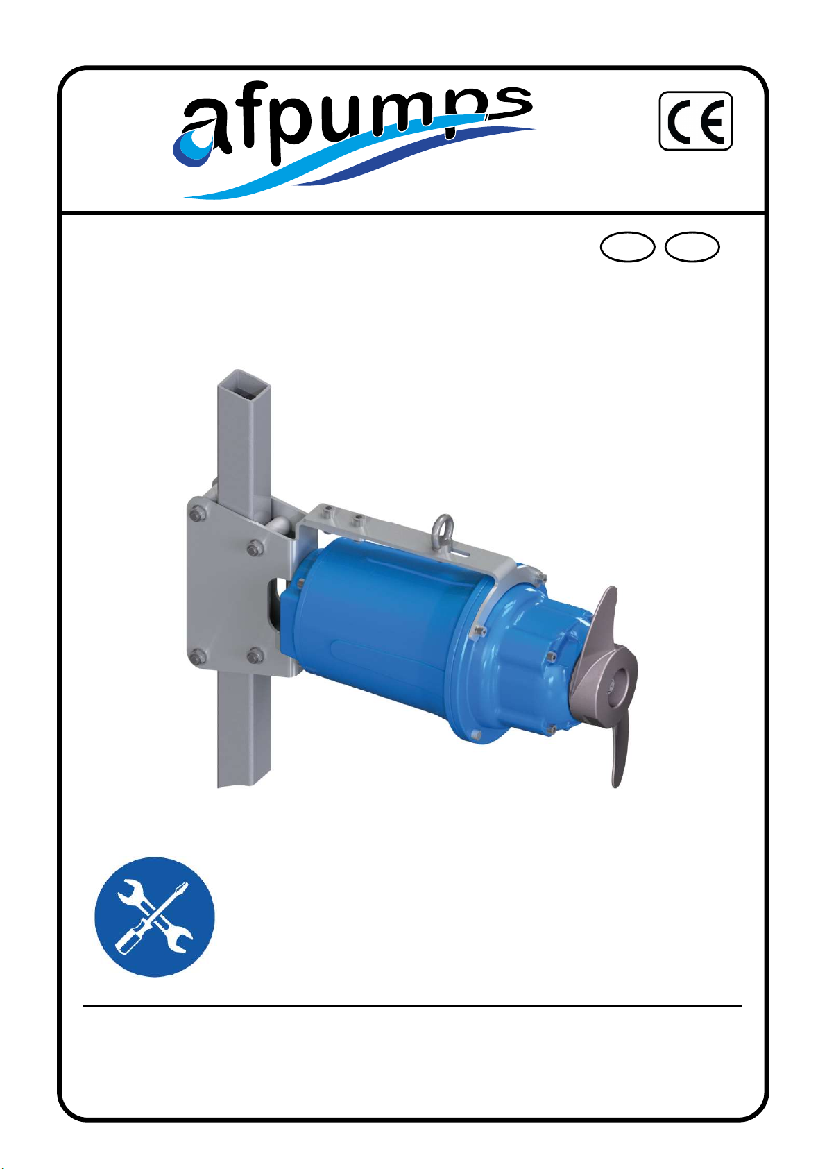
MIX
Manuale d’istruzione all’uso e alla manutenzione
Use and maintenance instruc ons manual
Instruc ons pour l’emploi et l’entre en
Benutzungs und Wartungshandbuch
Manual de Instruções, instalação e uso
IT 1
AFPUMPS S.r.l.
E-mail: [email protected]h p:// www.afpumps.com
Tel. +39 0429 77 82 95 - Fax +39 0429 76 30 49
IT
Questo manuale d’uso deve sempre rimanere a corredo della macchina anche nel caso di
trasferimento o vendita successiva le istruzioni devono essere rigorosamente seguite.
Manuale d’istruzione all’uso e alla manutenzione.
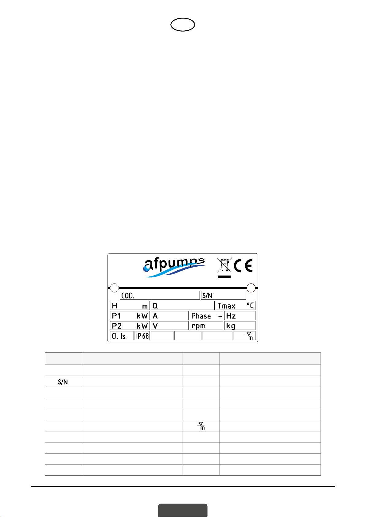
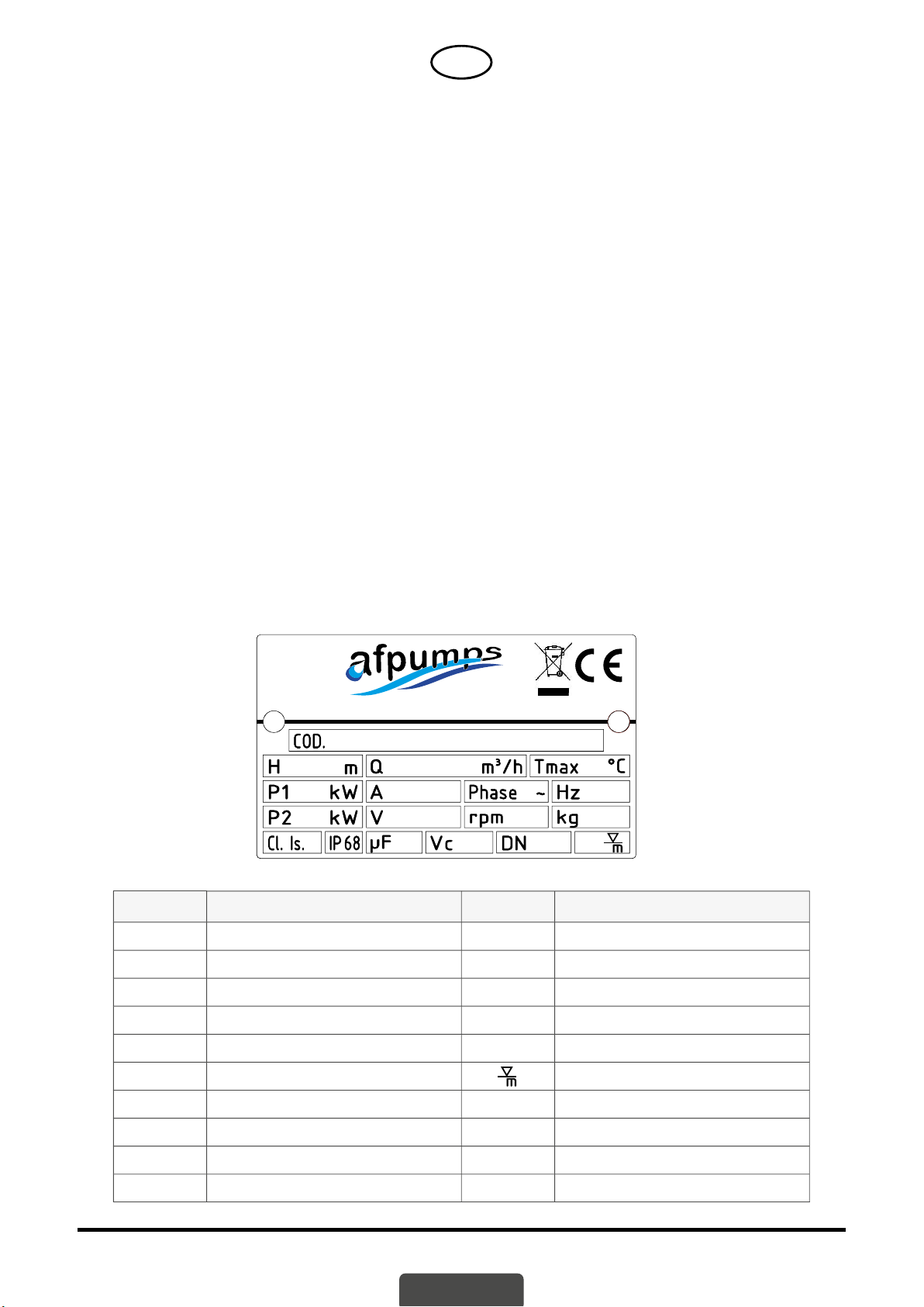
TARGHETTA IDENTIFICATIVA
Indice
Introduzione ...................................................................................................... IT - 1
Condizioni e limi d’impiego ............................................................................. IT - 2
Installazione ...................................................................................................... IT - 3
Pulizia ................................................................................................................ IT - 4
Temperatura so o zero ..................................................................................... IT - 4
Magazzinaggio................ ................................................................................. IT - 5
Collegamento ele rico ...................................................................................... IT - 5
Avviamento ....................................................................................................... IT - 6
Guas e rimedi .................................................................................................. IT - 7
Immagini - Disegni esplosi ................................................................................. IT - 8
Tipologia di fi ssaggio ......................................................................................... IT - 9
Dichiarazione di conformità .............................................................................. IT - 12
PERNUMIA (PD) MADE IN ITALY
Pos. Descrizione Pos. Descrizione
COD. Sigla completa miscelatore VTensione nominale
Anno di produz. / Numero di serie rpm Giri motore al minuto
HPrevalenza m.c.a. / Spinta Kg Peso miscelatore
QPortata CI.Is.F Classe d’isolamento
Tmax Temperatura max d’impiego IP 68 Grado di protezione
P1 Potenza Assorbita Massima immersione
AAssorbimento nominale
Phase Numero di fasi
H Frequenza
P2 Potenza resa

IT 2
AFPUMPS S.r.l.
E-mail: [email protected]h p:// www.afpumps.com
Tel. +39 0429 77 82 95 - Fax +39 0429 76 30 49
CONDIZIONI E LIMITI D’IMPIEGO
I miscelatori sommergibile AFPUMPS S.r.l. della serie MIX hanno lo scopo di omogeneizzare fanghi
pesan , di evitare la sedimentazione, cioé l’accumulo di detri sul fondo delle vasche e dei bacini di
raccolta di acque piovane, acque luride, ecc.
LIMITI D’IMPIEGO
• non lavorare con liquidi a temperature superiori a 40 °C, densità non superiore a 1100 kg/m3;
• PH compreso tra 6 e 10;
• livello minimo del liquido: il ba ente dell’acqua al di sopra dell’elica vedi pag. 9,10,11
• e/o sostanze chimicamente e meccanicamente aggressive per i materiali del miscelatore;
• e/o sostanze infi ammabili e/o esplosivi;
• in generale con cara eris che diverse da quelle specifi cate per ciascuna pologia di pompa.
Tu e le macchine non sono ada e ad essere installate in pozzi, vasche o altri ambien con
presenza di gas e/o pericolo di esplosione.
La massima profondità di immersione è per tu i miscelatori è pari a 20 m (con cavo di lunghezza
opportuna).
Per un funzionamento con nuo, al fi ne di consen re il corre o raff reddamento del motore, occorre
che lo stesso sia completamente immerso nel liquido da miscelare
Per evitare possibili danni al miscelatore, il numero di avviamen /ora equamente distribui deve
essere inferiore a 20.
RUMOROSITA’
Non applicabile perché il miscelatore lavora immerso nella vasca.
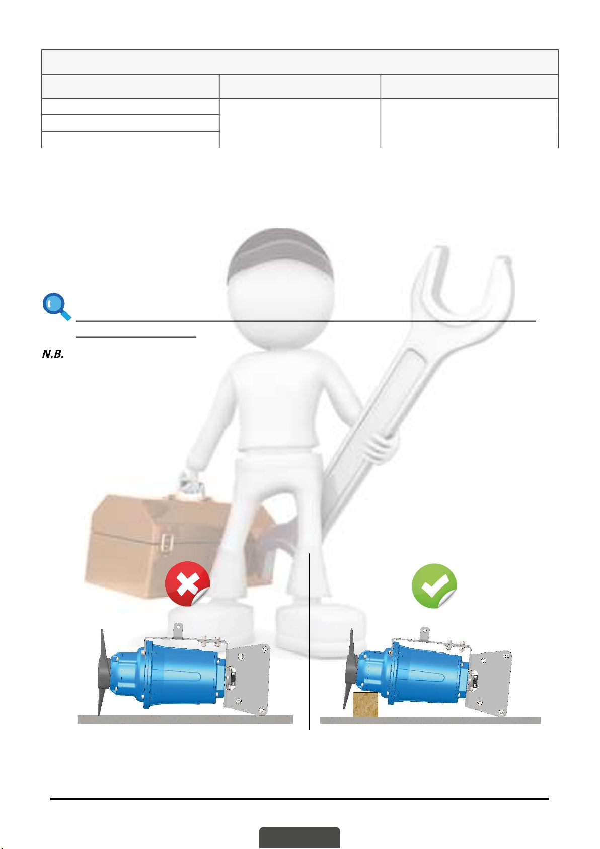
MOVIMENTAZIONE
• Non appoggiare il miscelatore sull’elica.
• Per la movimentazione del miscelatore non imballato, usufruire del gancio appositamente
predisposto sulla carcassa dello stesso.
• E’ assolutamente vietato sollevare il miscelatore tramite il cavo ele rico.
INSTALLAZIONE - Norme di sicurezza
Per prevenire il rischio di inciden durante la manutenzione o l’installazione del miscelatore, è
opportuno seguire le seguen norme:
• Non lavorare mai da soli. Usate cintura e corda di sicurezza, nonché una maschera an gas se
necessario. Non ignorate il pericolo di annegamento.
• Assicuratevi che ci sia suffi ciente ossigeno e che non ci sia presenza di gas velenosi.
• Controllate il rischio di esplosioni,prima di saldare o usare un a rezzo ele rico.
• Non ignorare il pericolo per la salute eosservate le norme igieniche.
• Fate a enzione ai rischi derivan da guas ele rici.
• Assicuratevi che l’a rezzatura per il sollevamento sia in buone condizioni.
• Provvedete ad uno sbarramento ada o intorno all’area dove lavorate.
• Assicuratevi di avere la possibilità di un veloce ritorno all’aria aperta.
• Usate casco, occhiali di sicurezza e scarpe di protezione.
• Tu e le persone che lavorano in stazioni di miscelazione di acque nere devono essere vaccinate
contro le possibili mala e che possono essere trasmesse.
• Non introdurre mai le mani vicino l’elica. A tale proposito si avverte che il miscelatore può
fermarsi e ripar re automa camente per l’intervento di protezioni termiche o telecomandi, per
cui solo l’interru ore dell’alimentazione elimina de o rischio.
• Il miscelatore deve essere u lizzato solo nel rispe o dei da indica sulla targhe a di
omologazione.
Il miscelatore è previsto per l’impiego in liquidi che possono essere dannosi alla salute.
IT 3
AFPUMPS S.r.l.
E-mail: [email protected]h p:// www.afpumps.com
Tel. +39 0429 77 82 95 - Fax +39 0429 76 30 49
Per prevenire eventuali danni agli occhi e alla pelle, osservate le seguen norme, in caso di intervento
sul miscelatore:
• Usate sempre occhiali an nfortunis ci e guan di gomma.
• Risciacquate bene il miscelatore con idropulitrice a caldo, prima di iniziare l’intervento.
• Risciacquate i diversi componen con acqua pulita, dopo averli smonta .
• Tenete uno straccio intorno alla vite della camera olio, quando dovete svitarla.Questo per evitare
che eventuali spruzzi raggiungano gli occhi o la pelle, qualora si fosse formata pressione nel
miscelatore a causa di infi ltrazioni di liquido miscelato.
Agite nel seguente modo, qualora prodo chimici nocivi dovessero venire a conta o.
Con i vostri occhi:
• Sciacquate immediatamente con acqua corrente per 15 minu , tenendo bene aperte le palpebre.
• Me etevi in conta o con un oculista.
Con la vostra pelle:
• Togliete gli abi contamina , lavate la pelle con acqua e sapone, se necessario fatevi controllare
da un medico.
SEGUITE TUTTE LE REGOLE DI IGIENE E SICUREZZA NONCHÉ LE EVENTUALI
ORDINANZE LOCALI.
INSTALLAZIONE - A rezzatura di sollevamento
Per sollevare il miscelatore, è necessaria un’apposita a rezzatura, essa deve poter alzare il miscelatore
e calarlo nella vasca, possibilmente senza la necessità di una ripresa.
La distanza minima tra il gancio di sollevamento e il bordo vasca dovrà essere secondo pag. 9-10 per
avere la possibilità di estrarre il miscelatore dalla vasca.
Un’a rezzatura di sollevamento sovradimensionata potrebbe causare danni al miscelatore,
qualora questo si incastrasse durante le operazioni di sollevamento. Assicuratevi che l’ancoraggio
dell’a rezzatura di sollevamento sia sicura.
ATTENZIONE! Tenetevi lontano dai carichi sospesi.
ISPEZIONI
Controlli periodici e manutenzioni preven ve garan scono un funzionamento più sicuro nel tempo.
Il miscelatore deve essere ispezionato almeno una volta all’anno e, in caso di funzionamento in
condizioni par colarmente gravose, occorre eseguire l’ispezione più frequentemente, in questa
occasione è necessario controllare lo stato dell’olio.
In condizioni normali di funzionamento, è consigliabile far revisionare il miscelatore in una offi cina
autorizzata ogni tre anni.
CAMBIO OLIO
Il riempimento della camera olio viene eseguito in fabbrica; qualora ci siano tracce di acqua o leggera
emulsione si rende necessario il cambio dell’olio. Bisogna estrarre il miscelatore dal pozze o, il tappo
dell’olio si trova lateralmente alla camera olio, consigliamo di eff e uare l’operazione presso una
offi cina autorizzata.
ATTENZIONE! In caso di infi ltrazioni dalla tenuta, la camera olio può essere in pressione.
Per prevenire spruzzi, tenete uno straccio intorno alla vite del serbatoio dell’olio, quando la svitate.
Svitare il tappo di chiusura della camera olio e fare fuoriuscire completamente l’olio, riempire quindi
con la quan tà prescri a di lubrifi cante (vedi Tab. 1), richiudete accuratamente e sos tuendo sempre
la stessa rose a di rame.
Se notate eviden tracce d’acqua o se l’olio è fortemente emulsionato, controllate la tenuta
meccanica inferiore se necessario sos tuitela, oppure rivolgetevi ad una offi cina autorizzata.
IT 4
AFPUMPS S.r.l.
E-mail: [email protected]h p:// www.afpumps.com
Tel. +39 0429 77 82 95 - Fax +39 0429 76 30 49
Tab.1
Modello Quantità olio motore Quantità olio pozzetto tenute
MIX 75-6
1,0 0,30MIX 100-4
MIX 150-4
PULIZIA
Non spedire il prodo o al fabbricante se è stato contaminato da una qualsiasi radiazione nucleare.
Informare il fabbricante in modo da poter prendere gli adegua provvedimen .
Accertarsi che la macchina e tu i componen siano sta adeguatamente puli e bonifi ca , prima
di spedire il prodo o al fabbricante.
Per pulire l’elica da corpi fi lamentosi può essere suffi ciente avviare il miscelatore per pochi secondi
con senso di rotazione inverso.
Se il miscelatore viene impiegato per l’uso saltuario, per evitare deposi ed incrostazioni, sarebbe
indispensabile pulirlo dopo ogni servizio mediante l’immersione e la miscelazione di acqua pulita,.
Dopo la pulizia lavare la vasca imme endo nella stessa acqua pulita.
AVVERTENZA: NON FORZATE IL MISCELATORE AD AVVIARSI PIÚ VOLTE SE INTERVIENE LA
PROTEZIONE TERMICA.
Prima di qualsiasi intervento di manutenzione e/o riparazione staccare l’alimentazione ele rica.
Non estrarre mai dall’acqua il miscelatore quando questo è ancora in funzione.
CON TEMPERATURE SOTTO ZERO
Il miscelatore non gela fi ntanto che rimane in funzione immerso nel liquido. Se il miscelatore viene
estra o dall’acqua, venendo quindi esposto a temperature so o zero, c’è pericolo che l’elica venga
bloccata dal gelo. Qualora l’elica fosse bloccata dal ghiaccio dovete immergere nuovamente il
miscelatore in acqua fi no all’avvenuto scongelamento.
Evitate di u lizzare altri metodi più veloci (es. scaldarla), per non arrecare danni al macchinario.
MAGAZZINAGGIO
Qualora il miscelatore venisse immagazzinato:
• me etelo dove sia prote a contro il caldo e l’umidità;
• curando a entamente la stabilità per evitare rotolamen o cadute.
Durante questo periodo di immagazzinaggio è consigliato ruotare a mano di tanto in tanto (almeno
ogni 2 mesi), per evitare che le tenute si incollino.
Se il miscelatore rimane fermo per oltre 6 mesi, la rotazione diventa obbligatoria.
Prima del riu lizzo del miscelatore assicurarsi che l’elica ruo liberamente.
IT 5
AFPUMPS S.r.l.
E-mail: [email protected]h p:// www.afpumps.com
Tel. +39 0429 77 82 95 - Fax +39 0429 76 30 49
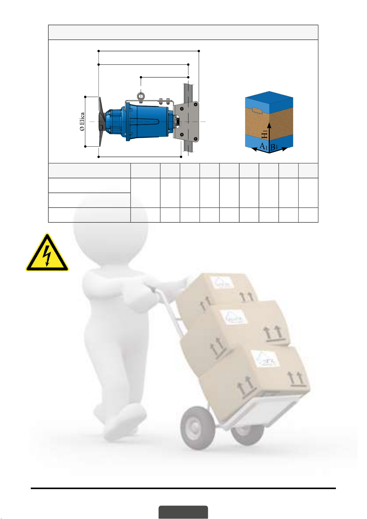
Dimensioni ingombri ed imballo.
L2
L
LM
L1
Modello Elica L L1L2LMH1A1B1Kg.
MIX 75-6
Ø 230 420 470 225 380 540 310 210 24
MIX 100-4
MIX 150-4 Ø 210 443 493 225 403 540 310 210 24
COLLEGAMENTO ELETTRICO
Il collegamento ele rico deve sempre essere eseguito da personale qualifi cato,
rispe ando le locali norma ve di legge. Assicurarsi che tensione e frequenza della
linea ele rica di alimentazione corrispondano a quelle indicate sulla targa del
miscelatore. Accertarsi che la linea ele rica di alimentazione abbia un effi ciente
impianto di terra ed eff e uare il collegamento a terra del miscelatore.
Il cavo ele rico di alimentazione non deve mai in nessun modo essere sollecitato, rato o piegato
con curve brusche. Durante l’installazione, assicurarsi che l’estremità libera del cavo di alimentazione
non venga mai immersa in acqua e che sia ben prote a contro possibili infi ltrazioni d’acqua o umidità.
Par colare a enzione deve essere riservata all’integrità del cavo: anche piccole escoriazioni possono
provocare infi ltrazioni nel motore ele rico. In caso di eventuali danni al cavo di alimentazione è
preferibile la sos tuzione e non la riparazione dello stesso: avvalersi in ogni caso sempre di personale
qualifi cato.
In caso di u lizzo di prolunghe, la giunzione deve rimanere all’asciu o e, per evitare cadute di
tensione eccessive, il cavo deve essere di sezione adeguata.
E’ sempre necessaria l’installazione di un’adeguata protezione ele rica (interru ore magnetotermico
opportunamente tarato e interru ore diff erenziale con corrente di intervento minore di 30 mA) in
grado di assicurare una disinserzione onnipolare dalla rete con una distanza di apertura dei conta
di almeno 3 mm.
Prima di qualsiasi intervento di manutenzione e/o riparazione del miscelatore, staccare
l’alimentazione ele rica.
Lo scostamento massimo ammesso tra l’eff e va tensione ele rica di alimentazione e il valore
nominale indicato sulla targa del miscelatore è pari al ± 10% (trifase).
IT 6
AFPUMPS S.r.l.
E-mail: [email protected]h p:// www.afpumps.com
Tel. +39 0429 77 82 95 - Fax +39 0429 76 30 49
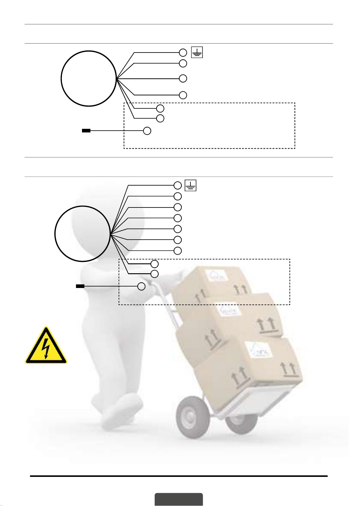
Collegamento ele rico TRIFASE: avviamento dire o Y
M
Y
(400 Volts)
Sonda termica T1 = Cavo n° 4 Nero = Bianco o Bianco/Nero
Sonda termica T2 = Cavo n° 5 Nero = Bianco o Bianco/Grigio
Sonda d’umidità = Cavo n° 6 Nero = Verde o Bianco/Marrone
KIT M/S = OPTIONAL
Linea 1 U1 = Cavo n° 1 Nero = Blu
Linea 2 V1 = Cavo n° 2 Nero = Marrone
Linea 3 W1 = Cavo n° 3 Nero = Nero
Giallo/Verde
Collegamento ele rico TRIFASE: avviamento Y/Δ
Sonda termica T1 = Cavo n° 7 Nero = Bianco o Bianco/Nero
Sonda termica T2 = Cavo n° 8 Nero = Bianco o Bianco/Grigio
Sonda d’umidità S = Cavo n° 9 Nero = Verde o Bianco/Marrone
KIT M/S = OPTIONAL
Linea 1 U1 = Cavo n° 1 Nero = Blu
Linea 2 V1 = Cavo n° 2 Nero = Marrone
Linea 3 W1 = Cavo n° 3 Nero = Nero
Linea 1 W2 = Cavo n° 4 Nero = Nero
Linea 2 U2 = Cavo n° 5 Nero = Blu
Linea 3 V2 = Cavo n° 6 Nero = Marrone
Giallo/Verde
M
Y/Δ
(400/690 Volts)
AVVIAMENTO
Prima di installare il miscelatore, bisogna accertarsi che, con la macchina non
collegata alla linea ele rica di alimentazione, il rotore giri liberamente: a tal fi ne si
può operare sull’elica. Occorre altresì verifi care che il senso di rotazione sia corre o,
ossia orario visto frontalmente rispe o la macchina.
Per fare ciò prima dell’installazione, sospendere il miscelatore ed avviare il motore
per pochi secondi (a acco e stacco): se il senso di rotazione è corre o, il miscelatore
subisce un contraccolpo in senso an orario vista frontalmente.Nell’eseguire questa prova, accertarsi
che la macchina sia a debita distanza da persone, animali o cose.
Per cambiare il senso di rotazione, inver re tra loro due fasi della linea di alimentazione.

IT 7
AFPUMPS S.r.l.
E-mail: [email protected]h p:// www.afpumps.com
Tel. +39 0429 77 82 95 - Fax +39 0429 76 30 49
GUASTI E RIMEDI
Qualsiasi modifi ca non autorizzata preven vamente, solleva il costru ore da ogni po di
responsabilità. Tu i pezzi di ricambio u lizza nelle riparazioni devono essere originali e tu
gli accessori devono essere autorizza dal costru ore, in modo da poter garan re la massima
sicurezza delle macchine e degli impian su cui queste possono essere montate.
INCONVENIENTI CAUSA RIMEDIO
Il motore non parte
e non genera rumori.
• Mancanza di elettricità. • Controllare il contattore della linea
elettrica.
• Spina non inserita. • Controllarne l’allacciamento.
• Interruttore automatico scattato. • Verificare la causa e riarmarlo.
• Protezione termica intervenuta. • Riattivarla se non è automatica.
• Fusibili di protezione bruciati. • Sostituirli con fusibili dello stesso
tipo.
• Motore difettoso. • Interpellare il rivenditore più vicino.
Il miscelatore
funziona ma con
fl usso rido o.
• L’elica è usurata. • Necessaria sostituizione.
• Livello dell’acqua troppo bassa. • Spegnere il miscelatore.
• Tensione di alimentazione errata. • Alimentare il miscelatore con la
tensione di targa.
• Verificare il senso di rotazione
dell’elica. • Controllare senso di rotazione.
Il miscelatore
non si arresta.
• L’interruttore non viene disattivato
dal temporizzatore. • Verificare la funzionalità e la libertà
di movimento e l’integrità del
temporizzatore.
Il miscelatore si arresta
dopo aver funzionato
poco tempo.
• Il dispositivo di protezione
termo-amperometrica arresta il
miscelatore.
• Verificare che il liquido da miscelare
non sia troppo denso, perchè
causerebbe il surriscaldamento del
motore.
• Temperatura del liquido troppo alta. • La temperatura oltrepassa i limiti
del campo d’impiego.
• Difetto interno. • Interpellare il rivenditore più vicino.
La garanzia del prodo o è sogge a alle condizioni generali di vendita AFPUMPS S.r.l.
Il riconoscimento della garanzia è vincolato allo scrupoloso e comprovato rispe o delle modalità dí
u lizzo contenute nel presente libre o, nonchè all’ applicazione delle buone regole meccaniche,
idrauliche ed ele rotecniche.

MIX 75-6 / 100-4 / 150-4
IT 8
AFPUMPS S.r.l.
E-mail: [email protected]h p:// www.afpumps.com
Tel. +39 0429 77 82 95 - Fax +39 0429 76 30 49
Pos. Descrizione Pos. Descrizione
6Pressacavo INOX 304 22 Tenuta a labbro
9O. Ring coperchio 24 Cassa motore GG25
10 Flangia portacuscine o GG25 25 Statore
12 Cuscine o superiore 30 Coperchio del motore GG25
13/14 Albero motore AISI 420 + rotore 41 Tenuta meccanica superiore in
ceramica/grafi te
15 Cuscine o inferiore
16 Elica INOX 304 42 Flangia tenura inferiore GG25
17 Lingue a 46 O.Ring cassa motore
21 Tenuta meccanica in widia-widia 47 O.Ring fl angia tenuta inferiore
6
30
9
24
46
10
47
42
12
25
15
17
22
21
41
16
13/14

MIX 75-6 / 100-4 / 150-4
IT 9
AFPUMPS S.r.l.
E-mail: [email protected]h p:// www.afpumps.com
Tel. +39 0429 77 82 95 - Fax +39 0429 76 30 49
Tipo "Q" con tubo quadro 40 x 40
Ø 12
Ø 12
1
2
3
4
Pos. Code Descrizione (Mat. AISI 304)
1LFV40.MIX Staff a fi x. tubo inferiore - Lower fi xing support
2L-SM40.MIX Staff a fi x. tubo superiore - Upper fi xing support
3
SFM.MX.100.4
Staff a guida mixer - Pipe guide mixer
4TQ304.40X40 Tubo guida 40 x 40 - Square pipe 40 x 40
-RS.47.506 Catena AISI 304 Ø 6 - AISI 304 chain Ø 6

MIX 75-6 / 100-4 / 150-4
IT 10
AFPUMPS S.r.l.
E-mail: [email protected]h p:// www.afpumps.com
Tel. +39 0429 77 82 95 - Fax +39 0429 76 30 49
Tipo “T” con tubo 2”e staff a a mensola
Ø 12
6
8
7
5
Pos. Code Descrizione (Mat. AISI 304)
5SCOR.MIXA Staff a fi x. mixer - Fixing mixer support
6Staff a orientabile mixer - Se ng mixer support
7TT304.60X3 Tubo 2" lungo 2 m - Pipe 2" lenght 2 m
8SMTOR_A Staff a a mensola - Braket shelf
MIX 75-6 / 100-4 / 150-4
IT 11
AFPUMPS S.r.l.
E-mail: [email protected]h p:// www.afpumps.com
Tel. +39 0429 77 82 95 - Fax +39 0429 76 30 49
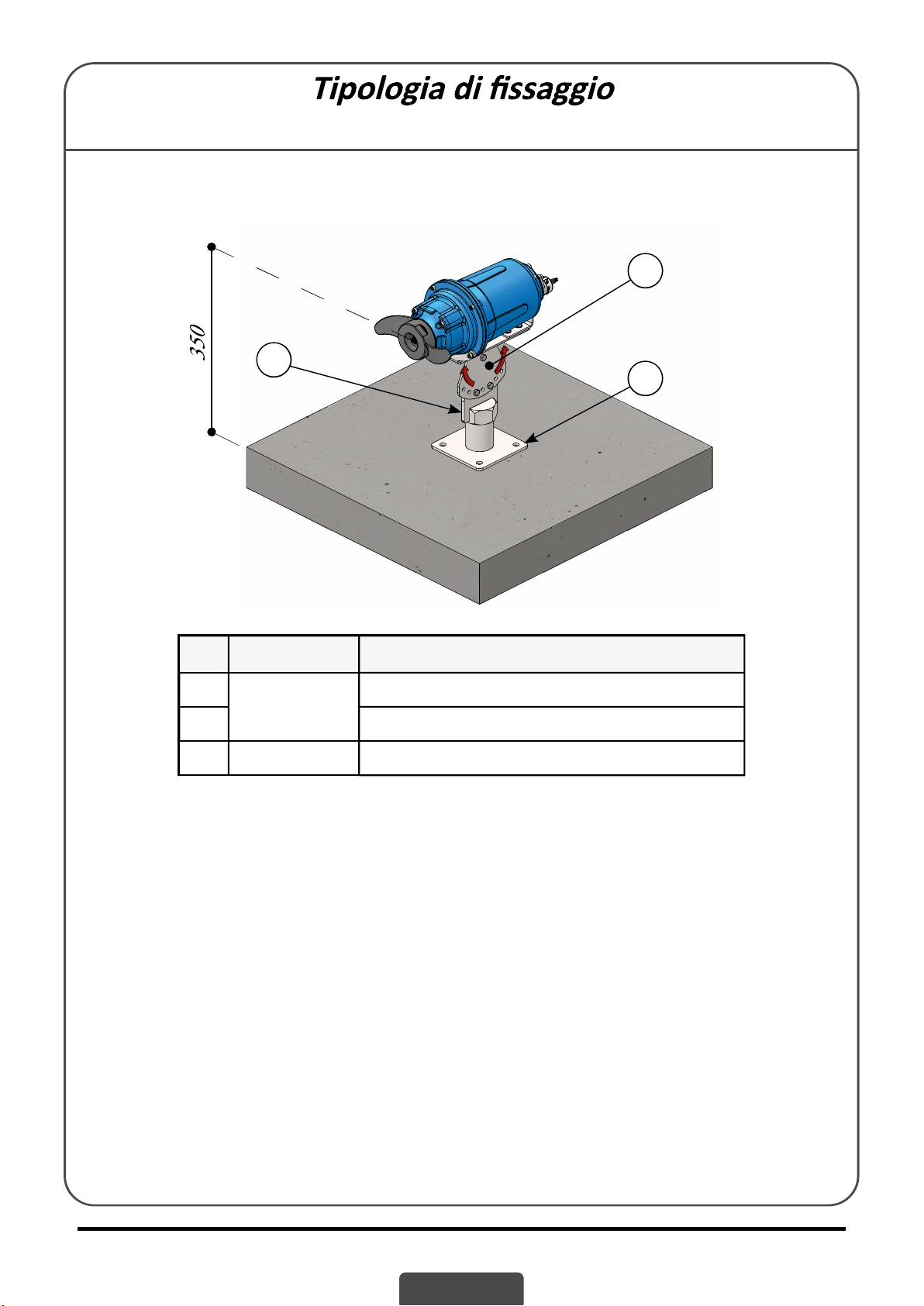
Tipo “Z” fi ssaggio su zavorra / fondo vasca
5
9
6
Pos. Code Descrizione (Mat. AISI 304)
5SCOR.MIXA Staff a fi x. mixer - Fixing mixer support
6Staff a orientabile mixer - Se ng mixer support
9SFZ.SCOR Staff a fi ssaggio zavorra - Ballast fi xing

IT 12
AFPUMPS S.r.l.
E-mail: [email protected]h p:// www.afpumps.com
Tel. +39 0429 77 82 95 - Fax +39 0429 76 30 49
DICHIARAZIONE DI CONFORMITÁ
AFPUMPS S.r.l.
Via dell’Ar gianato, 4 PERNUMIA (PD) - ITALY
so o la propria esclusiva responsabilità dichiara che i prodo
• MIX 75-6
• MIX 100-4
• MIX 150-4
• MIX 150-8
• MIX 200-6
Sono conformi alle seguen dire ve:
• Dire va Macchine 2006/42/CE
• Dire va Bassa Tensione 2014/35/EU
• Dire va compa bilità ele romagne ca 2014/30/EU
Le macchine sono inoltre costruite conformi alle seguen norme armonizzate:
• CEI EN 60335-1 (2013), 1/EC (2014), 1/A11 (2015)
• CEI EN 60335-2-41 (2005), 2-41/A2 (2010)
• CEI EN 55014-1/A11 (2020)
• CEI EN 55014-2 (2015)
• CEI EN 61000-3-2 (2015)
• CEI EN 61000-3-3 (2014)
Persona autorizzata alla compilazione del fascicolo tecnico in accordo con le
Dire ve sopra menzionate:
Nome: Sanavio Cris an
Indirizzo: Via dell’Ar gianato, 4 PERNUMIA (PD) IT
Pernumia, 05/10/2021 Il rappresentante legale
Sanavio Cris an
Il Costru ore declina ogni resposabilità per le possibili inesa ezze nel presente opuscolo, se dovute ad errori di
stampa o di trascrizione. Si riserva il diri o di apportare ai prodo quelle modifi che che riterrà necessarie od u li,
senza pregiudicarne le cara eris che essenziali.
SERIE: MIX
EN 1
AFPUMPS S.r.l.
E-mail: [email protected]h p:// www.afpumps.com
Tel. +39 0429 77 82 95 - Fax +39 0429 76 30 49
EN
This instruction manual should always be kept togheter with the unit, even when transferring
or selling the pump. The instructions are be followed with utmost care.
Use and maintenance instructions manual.
IDENTIFICATION PLATE
Index
Introduction ...................................................................................................... EN - 2
General satefy Warnings ..................................................................................... EN - 2
General description ............................................................................................ EN - 3
Cleaning ............................................................................................................. EN - 4
Below-zero temperatures .................................................................................. EN - 4
Storage............................................................................................................... EN - 4
Electrical connection .......................................................................................... EN - 5
Starting .............................................................................................................. EN - 6
Troubleshooting ................................................................................................. EN - 7
Images - Drawings ............................................................................................ EN - 8
Type of fi xing ..................................................................................................... EN - 9
Declaration of conformity .................................................................................. EN - 12
Pos. Descrizione Pos. Descrizione
COD. Mixer type VRated voltage
Month Year of production rpm r.p.m.
HHead range / Trust Kg Weight of the mixer
QCapacity range CI.Is.F Insulation class
Tmax Max work temperature IP 68 Degrée of protection
P1 Absorbed power Max. Submersible level
AAbsorbed current μF Capacitor
Phase Number of phases Vc Voltage to the capacitor
H Frequency
P2 Motor power
PERNUMIA (PD) MADE IN ITALY
-
- - -
-
-
F -
- - -
- - -
- - 20

EN 2
AFPUMPS S.r.l.
E-mail: [email protected]h p:// www.afpumps.com
Tel. +39 0429 77 82 95 - Fax +39 0429 76 30 49
WORKING CONDITIONS AND LIMITATIONS
AFPUMPS S.r.l. submersible mixer MIX series are used for homogenisa on of heavy sludge,
to prevent the sedimenta on and esactly the accumula on of debris such as solids and
sludge at the bo om of the pumping sta on and rainwater catchments, sewage, etc.
OPERATING LIMITS
• with a temperature above 40 °C, density above 1100 kg/m3;
• with pH range between 6 and 10;
• minimum liquid level: water head above the propeller, see pag. 9,10,11
• containing chemically and mechanically aggressive substances for the materials the mixer is
made from;
• containing infl ammable or explosive substances;
• any other liquids with diff erent proper es to those specifi ed for each type of pump.
None of the machines are suitable for installing in wells, tanks or other places where there is
gas and/or risk of explosion.
The maximum immersion depth for all the power mixer is 20 m (with a cable of the right length).
For con nuous opera ons and to allow the motor to cool down correctly, the pump must be
completely immersed in the liquid being mixed.
To prevent damage to the power mixer, the number of starts/hour evenly distributed must be less
20.
ACOUSTIC PRESSURE
Not applicable because the mixer works immersed in the tank.
HANDLING
• Don’t lay the mixer on the propeller
• For the handling of the mixer not packed, use the hook specially prepared on the casing of the
same.
• The mixer must never be carried, li ed or made to operate hanging from their power cable
INSTALLATION - Safety rules
To prevent the risk of accidents during the maintenance or installa on of the mixer, the following
rules should be followed:
• Never work alone. Use a safety belt and rope, as well as a gas mask if necessary. Don’t ignore the
danger of drowning.
• Make sure there is suffi cient oxygen and that there is no poisonous gas present.
• Check for the risk of explosion before welding or using a power tool.
• Do not ignore the health hazard and observe hygiene rules.
• Be aware of the risks deriving from electrical failures.
• Make sure the li ing equipment is in good condi on.
• Provide a suitable barrier around the area where you work.
• Make sure you have the possibility of a quick return to the open air.
• Use a helmet, safety glasses and protec ve shoes.
• All people working in black water mixing sta ons must be vaccinated against possible diseases
that can be transmi ed.
• Never put your hands near the propeller. In this regard, it is warned that the mixer can stop and
restart automa cally due to the interven on of thermal protec ons or remote controls, so only
the power switch eliminates this risk.
• The mixer must only be used in compliance with the data indicated on the approval plate.
The mixer is intended for use in liquids that can be harmful to health.

EN 3
AFPUMPS S.r.l.
E-mail: [email protected]h p:// www.afpumps.com
Tel. +39 0429 77 82 95 - Fax +39 0429 76 30 49
To prevent damage to the eyes and skin, observe the following rules when working on the mixer:
• Always use safety goggles and rubber gloves.
• Rinse the mixer well with a hot pressure washer before star ng the opera on.
• Rinse the various components with clean water a er having disassembled them.
• Keep a rag around the oil chamber screw when you need to unscrew it to prevent any splashes
from reaching your eyes or skin if pressure has built up in the mixer due to infi ltra on of mixed
liquid.
Do the following if harmful chemicals come into contact.
With your eyes:
• Rinse immediately with running water for 15 minutes, keeping the eyelids wide open.
• Contact an ophthalmologist.
With your skin:
• Remove contaminated clothes, wash your skin with soap and water, if necessary get checked by
a doctor.
FOLLOW ALL THE RULES OF HYGIENE AND SAFETY AS WELL AS ANY LOCAL ORDINANCES.
INSTALLATION - Li ing equipment
To li the mixer, special equipment is required, it must be able to li the mixer and lower it into the
tank, possibly without the need for a recovery.
The minimum distance between the li ing hook and the edge of the pool must be according to pag.
9-10 to have the possibility to extract the mixer from the tank.
Oversized li ing equipment could cause damage to the mixer if it gets stuck during li ing opera ons.
Make sure that the anchoring of the li ing equipment is safe.
ATTENTION! Keep away from suspended loads.
INSPECTION
Periodic checks and preven ve maintenance ensure safer opera on over me.
The mixer must be inspected at least once a year and, in case of opera on in par cularly severe
condi ons, it is necessary to perform the inspec on more frequently, on this occasion it is necessary
to check the state of the oil.
Under normal opera ng condi ons, it is advisable to have the mixer overhauled in an authorized
workshop every three years.
OIL CHANGE
The oil chamber is fi lled in the factory; if there are traces of water or a light emulsion, it is necessary
to change the oil. It is necessary to remove the mixer from the well, the oil cap is located on the side
of the oil chamber, we recommend carrying out the opera on at an authorized workshop.
ATTENTION! In the event of leaks from the seal, the oil chamber may be under pressure.
To prevent splashing, hold a rag around the oil tank screw when you unscrew it.
Unscrew the closing cap of the oil chamber and drain the oil completely, then fi ll with the prescribed
amount of lubricant (see Table 1), close carefully and always replacing the same copper washer.
If you no ce obvious traces of water or if the oil is heavily emulsifi ed, check the lower mechanical
seal if necessary, replace it, or contact an authorized workshop.

EN 4
AFPUMPS S.r.l.
E-mail: [email protected]h p:// www.afpumps.com
Tel. +39 0429 77 82 95 - Fax +39 0429 76 30 49
Tab.1
Model Oil motor quantity Mechanical seal chamber oil quantity
MIX 75-6
1,0 0,30MIX 100-4
MIX 150-4
CLEANING
Do not ship the product to the manufacturer if it has been contaminated by any nuclear radia on.
Inform the manufacturer so that appropriate measures can be taken.
Make sure that the machine and all components have been properly cleaned and reclaimed before
sending the product to the manufacturer.
To clean the propeller of fi lamentary bodies, it may be suffi cient to start the mixer for a few seconds
with reverse rota on direc on.
If the mixer is used for occasional use, to avoid deposits and encrusta ons, it would be essen al to
clean it a er each service by immersing and mixing clean water. A er cleaning, wash the tank by
pu ng it in the same clean water.
WARNING: DO NOT FORCE THE MIXER TO START SEVERAL TIMES IF THE THERMAL
PROTECTION INTERVENT.
Before any maintenance and / or repair work, disconnect the power supply.
Never remove the mixer from the water when it is s ll running.
BELOW ZERO TEMPERATURES
The mixer does not freeze as long as it is running immersed in the liquid. If the mixer is extracted
from the water, thus being exposed to temperatures below zero, there is a danger that the propeller
will be blocked by frost. If the propeller is blocked by ice, you must immerse the mixer again in water
un l it has thawed.
Avoid using other faster methods (eg hea ng it), in order not to damage the machine.
STORAGE
If the mixer will be storaged:
• put it where it is protected against heat and humidity;
• taking care of stability carefully to avoid rolling or falling.
During this storage period it is recommended to rotate by hand from me to me (at least every 2
months), to prevent the seals from s cking together.
If the mixer remains sta onary for more than 6 months, rota on becomes mandatory.
Before reusing the mixer, make sure that the propeller rotates freely.

EN 5
AFPUMPS S.r.l.
E-mail: [email protected]h p:// www.afpumps.com
Tel. +39 0429 77 82 95 - Fax +39 0429 76 30 49
Overall dimensions and packaging.
L2
L
LM
L1
Model Propeller L L1L2LMH1A1B1Kg.
MIX 75-6
Ø 230 420 470 225 380 540 310 210 24
MIX 100-4
MIX 150-4 Ø 210 443 493 225 403 540 310 210 24
ELECTRICAL CONNECTION
The electrical connec on must always be carried out by qualifi ed personnel,
respec ng the local legal regula ons. Make sure that the voltage and frequency of
the power supply line correspond to those indicated on the nameplate of the mixer.
Make sure that the power supply line has an effi cient earth system and connect the
mixer to earth.
The power supply cable must never in any way be stressed, pulled or bent with sharp bends. During
installa on, make sure that the free end of the power cable is never immersed in water and that it is
well protected against possible infi ltra on of water or humidity.
Par cular a en on must be paid to the integrity of the cable: even small abrasions can cause
infi ltra on into the electric motor. In the event of any damage to the power supply cable, it is
preferable to replace it rather than repair it: always use qualifi ed personnel in any case.
When using extensions, the junc on must remain dry and, to avoid excessive voltage drops, the
cable must have an adequate sec on.
It is always necessary to install adequate electrical protec on (suitably calibrated magnetothermic
switch and diff eren al switch with tripping current lower than 30 mA) capable of ensuring omnipolar
disconnec on from the mains with a contact opening distance of at least 3 mm.
Before any maintenance and / or repair of the mixer, disconnect the power supply.
The maximum allowable devia on between the actual power supply voltage and the nominal value
indicated on the mixer plate is ± 10% (three-phase).

EN 6
AFPUMPS S.r.l.
E-mail: [email protected]h p:// www.afpumps.com
Tel. +39 0429 77 82 95 - Fax +39 0429 76 30 49
THREEPHASE electrical connec on: direct start Y
M
Y
(400 Volts)
Thermal probe T1 = Cable n° 4 Black = White or White/Black
Thermal proble T2 = Cable n° 5 Black = White or White/Grey
Umidity probe = Cable n° 6 Black = Green or White/Brown
KIT M/S = OPTIONAL
Line 1 U1 = Cable n° 1 Black = Blue
Line 2 V1 = Cable n° 2 Black = Brown
Line 3 W1 = Cable n° 3 Black = Black
Yellow/Green
THREEPHASE electrical connec on: start Y/Δ
Thermal probe T1 = Cable n° 7 Black = White or White/Black
Thermal probe T2 = Cable n° 8 Black = White or White/Grey
Umidity probe S = Cable n° 9 Black = Green or White/Brown
KIT M/S = OPTIONAL
Line 1 U1 = Cable n° 1 Black = Blu
Line 2 V1 = Cable n° 2 Black = Brown
Line 3 W1 = Cable n° 3 Black = Black
Line 1 W2 = Cable n° 4 Black = Black
Line 2 U2 = Cable n° 5 Black = Blue
Line 3 V2 = Cable n° 6 Black = Brown
Yellow/Green
M
Y/Δ
(400/690 Volts)
START
Before installing the mixer, you must make sure that, with the machine not connected
to the power supply line, the rotor rotates freely: for this purpose you can operate on
the propeller. It is also necessary to check that the direc on of rota on is correct, ie
clockwise viewed from the front of the machine.
To do this, before installa on, suspend the mixer and start the engine for a few
seconds (staryt and stop): if the direc on of rota on is correct, the mixer undergoes
a counterclockwise kickback when viewed from the front. When carrying out this test, make sure
that the machine is at a safe distance from people, animals or things.
To change the direc on of rota on, swap two phases of the power supply line together.

EN 7
AFPUMPS S.r.l.
E-mail: [email protected]h p:// www.afpumps.com
Tel. +39 0429 77 82 95 - Fax +39 0429 76 30 49
TROUBLESHOOTING
Any modifi ca on not authorized in advance relieves the manufacturer from any kind of
responsibility. All spare parts used in repairs must be original and all accessories must be
authorized by the manufacturer, in order to ensure maximum safety of the machines and systems
on which they can be mounted.
FAULT CAUSE REMEDY
The motor does not start
and makes no noise. • No ele ric power. • Check the contactor on the electric
line.
• Plug not inserted. • Check power connec on to the line.
• Automa c switch has tripped. • Reset the switch, check the cause.
• Thermal protec on has tripped. • This resets automa cally (Single-
• Protec on fuses are burnt out. • Replace the fuses with others of the
same type.
• Faulty motor or capacitor. • Contact the nearest dealer.
The mixer works but with
lower fl ow.
• The propeller is worn out. • Replacement required.
• Water level too low. • Turn off the mixer.
• Wrong power supply voltage. • Power the mixer with the rated
voltage.
• Check the direction of rotation of
the propeller. • Check direction of rotation.
Mixer don’t stop. • The switch is not disabled by the
timer. • Check the functionality and
freedom of movement and integrity
of the timer.
The mixer stops a er
running for a short me.
• The thermo-amperometric
protection device stops the mixer. • Check that the liquid to be mixed is
not too thick, as it would cause the
motor to overheat.
• Liquid temperature too high. • The temperature exceeds the limits
of the field of use.
• Internal defect. • Contact the nearest dealer.
The product warranty is subject to the general condi ons of sale AFPUMPS S.r.l.
The recogni on of the guarantee is bound to the scrupulous and proven compliance with the me-
thods of use contained in this booklet, as well as to the applica on of good mechanical, hydraulic
and electrical engineering rules.
Table of contents
Languages:
Other AFPUMPS Water Pump manuals

Popular Water Pump manuals by other brands


Becker
Becker VARIAIR DTLF 2.500/0-400 operating instructions

BOC Edwards
BOC Edwards 18B4B instruction manual

Grundfos
Grundfos ALPHA 15-55 HWR-T Installation and operating instructions

NewTeam
NewTeam Singlespeed Installation instructions and user guide

Whale
Whale Gulper BP2552B manual

Wilo
Wilo Atmos PICO Installation and operating instructions

Kolmeks
Kolmeks SC-SERIES operating instructions

Hamron
Hamron 006780 operating instructions

STA-RITE
STA-RITE DURA-JET 5JSAC-A owner's manual

Stübbe
Stübbe ETLB-S series Original operating manual

GORMAN-RUPP PUMPS
GORMAN-RUPP PUMPS PRIME-AIRE Series manual

Pfeiffer Vacuum
Pfeiffer Vacuum MVP 160-3 operating instructions