Stübbe ETLB-S series Installation instructions

Plastic
Sump Pump
Original operating manual Series
ETLB-S
ETLB-ST
Version BA-2018.01.25 EN
Print-No. 301 356
TR MA DE Rev001
Subject to technical modi¿cations.
Read carefully before use.
Save for future use.
Distributed in the UK by.....
Pump Engineering Limited.Unit B1, Riverside Industrial Estate,
Littlehampton, West Sussex, BN17 5DF, United Kingdom
Tel: 01903 730900 Fax: 01903 730234

Table of contents
Table of contents
1 About this document ............................... 4
1.1 Target groups ................................. 4
1.2 Other applicable documents ................ 4
1.3 Warnings and symbols ....................... 5
2 Safety ................................................. 6
2.1 Intended use .................................. 6
2.2 General safety instructions .................. 6
2.2.1 Product safety ................................ 6
2.2.2 Obligations of the operating company . ..... 7
2.2.3 Obligations of personnel ..................... 7
2.3 Speci¿c hazards .............................. 7
2.3.1 Hazardous pumped liquids .................. 7
3 Layout and function ................................ 8
3.1 Marking ....................................... 8
3.1.1 Name plate ................................... 8
3.2 Description .................................... 8
3.3 Assembly ..................................... 8
4 Transport, storage and disposal .................. 9
4.1 Transport ...................................... 9
4.1.1 Unpacking and inspection on delivery . . . . .. 9
4.1.2 Lifting ......................................... 9
4.2 Storage ....................................... 10
4.3 Disposal ....................................... 10
5 Setup and connection .............................. 11
5.1 Preparing for installation .................... 11
5.1.1 Checking the operating conditions for the
ETLB-S ....................................... 11
5.1.2 Checking the operating conditions for the
ETLB-ST ...................................... 11
5.1.3 Preparing the installation site ............... 12
5.1.4 Surface preparation .......................... 12
5.2 Setting up ..................................... 12
5.3 Planning pipelines ............................ 12
5.3.1 Specifying supports and Àange
connections ................................... 12
5.3.2 Specifying nominal widths ................... 12
5.3.3 Optimizing changes of cross section and
direction ....................................... 12
5.3.4 Providing safety and control devices
(recommended) .............................. 12
5.4 Fitting the accessory part .................... 13
5.4.1 Preparing the accessory part ................ 13
5.4.2 Checking the operating conditions for the
accessory part ................................ 13
5.4.3 Fitting the accessory part .................... 13
5.5 Connecting the pipes ........................ 14
5.5.1 Keeping the piping clean .................... 14
5.5.2 Installing the pressure pipe .................. 14
5.5.3 Inspection for stress-free pipe
connections ................................... 14
5.6 Electrical connection ......................... 15
5.6.1 Connecting the motor ........................ 15
5.6.2 Connecting the thermistor ................... 15
5.6.3 Check direction of rotation ................... 15
5.7 Performing the hydrostatic test .............. 15
6Operation ............................................ 16
6.1 Preparing for commissioning ................ 16
6.1.1 Check downtimes ............................ 16
6.1.2 Filling and bleeding .......................... 16
6.2 Commissioning ............................... 16
6.2.1 Switching on .................................. 16
6.2.2 Switching off .................................. 17
6.3 Shutting down the pump ..................... 17
6.4 Restoring the pump to service .............. 18
6.5 Operating the stand-by pump ............... 18
7 Maintenance ......................................... 19
7.1 Inspections ................................... 19
7.2 Servicing ...................................... 19
7.2.1 Maintenance in accordance with maintenance
schedule ...................................... 19
7.2.2 Cleaning the pump ........................... 19
7.3 Dismounting .................................. 20
7.3.1 Preparations for dismounting ................ 20
7.3.2 Disassembly of spiral casing ................ 21
7.4 Replacement parts and return .............. 21
7.5 Installing ...................................... 22
8Troubleshooting .................................... 23
9Appendix............................................. 25
9.1 Replacement parts ........................... 25
9.1.1 Part numbers and designations ......... . . . . 25
9.1.2 Sectional drawings ........................... 26
9.2 Technical speci¿cations ...................... 31
9.2.1 Ambient conditions ........................... 31
9.2.2 Sole plate tightening torques . . . . . . . . . . .. . . . . 31
9.2.3 Tightening torques of casing screws . . .... . . 31
9.2.4 Filling heights and installation
dimensions ................................... 31
9.2.5 Flange tightening torques ................... 31
9.2.6 Permissible forces at the pressure
socket ......................................... 31
9.2.7 Sound pressure level ........................ 32
9.3 Maintenance schedule ....................... 32
9.4 Declaration of conformity in accordance with
EC machinery directive ...................... 33
2 ETLB-S, ETLB-ST BA-2018.01.25 EN 301 356

Table of contents
List of ¿gures
Fig. 1 Name plate (example) ....................... 8
Fig. 2 Assembly ..................................... 8
Fig. 3 Attaching lifting gear to the pump unit . . . ... 9
Fig. 4 Mounting the ETLB-S pump on containers
(example with suction extension) ........... 11
Fig. 5 Mount the ETLB-ST pump on a supporting
structure ...................................... 11
Fig. 6 Installation of accessory parts ............... 13
Fig. 7 Sectional view 1 .............................. 26
Fig. 8 Sectional view 2 .............................. 26
Fig. 9 Exploded drawing ............................ 26
Fig. 10 Sectional view 1 .............................. 27
Fig. 11 Sectional view 2 .............................. 27
Fig. 12 Exploded drawing ............................ 27
Fig. 13 Sectional view 1 .............................. 28
Fig. 14 Sectional view 2 .............................. 28
Fig. 15 Exploded drawing ............................ 28
Fig. 16 Sectional view 1 .............................. 29
Fig. 17 Sectional view 2 .............................. 29
Fig. 18 Exploded drawing ............................ 29
Fig. 19 Sectional view 1 .............................. 30
Fig. 20 Sectional view 2 .............................. 30
Fig. 21 Exploded drawing ............................ 30
Fig. 22 Permissible forces at the pressure
socket ......................................... 31
List of tables
Tab. 1 Other application documents, purpose and
where found .................................. 4
Tab. 2 Warnings and symbols ....................... 5
Tab.3 Measurestobetakenifthepumpisshut
down .......................................... 17
Tab. 4 Measures depending on the behavior of the
pumped liquid ................................ 17
Tab. 5 Fault/number assignment ................... 23
Tab. 6 Troubleshooting list .......................... 24
Tab. 7 Designation of components according to part
numbers ...................................... 25
Tab. 8 Ambient conditions ........................... 31
Tab. 9 Sole plate tightening torques ................ 31
Tab. 10 Tightening torques of casing screws ... . . . . . 31
Tab. 11 Tightening torques ........................... 31
Tab. 12 Noise level LpA to DIN EN ISO 11203 ... . .. 32
Tab. 13 Maintenance schedule ....................... 32
301 356 BA-2018.01.25 EN ETLB-S, ETLB-ST 3
About this document
1 About this document
This manual:
• is part of the equipment
• applies to all series referred to
• describes safe and proper operation during all operating
phases
1.1 Target groups
Operating company
• Responsibilities:
– Always keep this manual accessible where the device
is used on the system.
– Ensure that employees read and observe this docu-
ment, particularly the safety instructions and warnings,
and the documents which also apply.
– Observe any additional country-speci¿c rules and reg-
ulations that relate to the system.
Quali¿ed personnel, ¿tter
• Mechanics quali¿cation:
–Quali¿ed employees with additional training for ¿tting
therespectivepipework
• Electrical quali¿cation:
–Quali¿ed electrician
• Transport quali¿cation:
–Quali¿ed transport specialist
• Responsibility:
– Read, observe and follow this manual and the other
applicable documents, especially all safety instructions
and warnings.
1.2 Other applicable documents
To download:
Resistance lists
Resistance of materials used to
chemicals
www.asv-stuebbe.de/pdf_resistance/300051.pdf
To download:
Data sheet
Technical data and conditions of
operation
www.asv-stuebbe.de/pdf_datasheets/300209.pdf
To download:
CE declaration of conformity
Conformity with standards
www.asv-stuebbe.de/pdf_DOC/300145.pdf
Supplier documentation
• Technical documentation for parts
supplied by subcontractors
Documentation
included
Tab. 1 Other application documents, purpose
and where found
4 ETLB-S, ETLB-ST BA-2018.01.25 EN 301 356
About this document
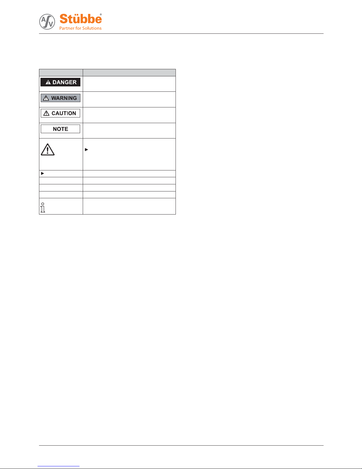
1.3 Warnings and symbols
Symbol Meaning
• Immediate acute risk
• Death, serious bodily harm
• Potentially acute risk
• Death, serious bodily harm
• Potentially hazardous situation
• Minor injury
• Potentially hazardous situation
• Material damage
Safety warning sign
Take note of all information
highlighted by the safety warning
sign and follow the instructions to
avoid injury or death.
Instruction
1., 2., ... Multiple-step instructions
9Precondition
ĺCross reference
Information, notes
Tab. 2 Warnings and symbols
301 356 BA-2018.01.25 EN ETLB-S, ETLB-ST 5

Safety
2 Safety
The manufacturer accepts no liability for damage caused
by disregarding any of the documentation.
2.1 Intended use
• Only use the pump with suitable media (ĺresistance lists).
• When using the pumps for solid particles, agree use in
advance with the manufacturer.
• Do not use pump for combustible or explosive Àuids.
• Adhere to the operating limits and size-dependent mini-
mum Àow rates.
• Avoid cavitation:
– Open the suction-side ¿tting and do not use it to regu-
late the Àow.
– Do not open the pressure-side ¿tting beyond the
agreed operating point.
• Avoid overheating:
– Do not operate the pump while the pressure-side ¿tting
is closed.
• Avoid damage to the motor:
– Do not open the pressure-side ¿tting beyond the
agreed operating point.
– Note the maximum permissible number of times the
motor can be switched on per hour (ĺmanufacturer's
speci¿cations).
• Only use the pump as part of large systems/tools.
• Consult with the manufacturer regarding any other use of
the device.
Prevention of obvious misuse (examples)
• Observe pump limits of use regarding temperature, pres-
sure, Àow and speed (ĺdata sheet).
• The power consumption of the pump increases as the spe-
ci¿c gravity of the pumped Àuid increases. Adhere to the
permissible speci¿c gravity in order to eliminate thepos-
sibility that the pump, coupling and motor become over-
loaded (ĺdata sheet).
A lower speci¿c gravity is permissible. Adapt the auxiliary
systems accordingly.
• Pumps used with water as the pumped liquid must not be
used for foodstuffs or drinking water. Use for food or drink-
ing water only if speci¿ed in the data sheet.
• The type of installation should be selected only in accor-
dance with these operating instructions. For example, the
following are not allowed:
– Hanging base plate pumps in the pipe
– Overhead installation
– Installation in the immediate vicinity of extreme heat or
cold sources
– Installation too close to a wall
2.2 General safety instructions
Observe the following regulations before carrying out any
work.
2.2.1 Product safety
The pump has been built according to state-of-the-art technol-
ogy and the recognized technical safety regulations. Never-
theless, operation of the pump can still put the life and health
of the user or third parties at risk or damage the pump or other
property.
• Operate the pump only if it is in perfect technical condition
and use it only as intended, staying aware of safety and
risks, and in adherence to the instructions in this manual.
• Keep this manual and all other applicable documents com-
plete, legible and accessible to personnel at all times.
• Refrain from any procedures and actions that would pose
a risk to personnel or third parties.
• In the event of any safety-relevant faults, shut down the
pump immediately and have the fault corrected by appro-
priate personnel.
• In addition to the entire documentation for the product,
comply with statutory or other safety and accident-preven-
tion regulations and the applicable standards and guide-
lines in the country where the pump is operated.
6 ETLB-S, ETLB-ST BA-2018.01.25 EN 301 356

Safety
2.2.2 Obligations of the operating company
Safety-conscious working
• Operate the pump only if it is in perfect technical condition
and use it only as intended, staying aware of safety and
risks, and in adherence to the instructions in this manual.
• Ensure that the following safety aspects are observed and
monitored:
– Intended use
– Statutory or other safety and accident-prevention reg-
ulations
– Safety regulations governing the handling of haz-
ardous substances
– Applicable standards and guidelines in the country
where the pump is operated
– Applicable guidelines of the operator
• Make personal protective equipment available.
Quali¿ed personnel
• Make sure all personnel tasked with work on the pump
have read and understood this manual and all other appli-
cable documents, especially the safety, maintenance and
repair information, before they start any work.
• Organize responsibilities, areas of competence and the
supervision of personnel.
• Ensure that all work is carried out by specialist technicians
only:
– Installation, repair and maintenance work
– Transportation
– Work on the electrical system
• Make sure that trainee personnel only work on the pump
under supervision of specialist technicians.
Safety equipment
• Provide the following safety equipment and verify its func-
tionality:
– For hot, cold and moving parts: pump safety guarding
provided by the customer
– For pumps without capability to run dry: Dry run pro-
tection
– For potential electrostatic charging: provide suitable
grounding
Warranty
• Obtain the manufacturer's approval prior to carrying out
any modi¿cations, repairs or alterations during the warranty
period.
• Only use genuine parts or parts that have been approved
by the manufacturer.
2.2.3 Obligations of personnel
• All directions given on the pump must be followed (and kept
legible), e.g. the arrow indicating the sense of rotation and
the markings for Àuid connections.
• Pump, coupling guard and components:
– Do not step on them or use as a climbing aid
– Do not use them to support boards, ramps or beams
– Donotusethemasa¿xing point for winches or sup-
ports
– Do not use them for storing paper or similar materials
– Do not use the hot pump or motor components as a
heating point
– Do not de-ice the pump using gas burners or similar
tools
• Do not remove the safety guarding for hot, cold or moving
parts during operation.
• Use personal protective equipment if necessary.
• Only carry out work on the pump while it is not running.
• Before all installation and maintenance work, disconnect
the motor from the mains and secure it against being
switched back on again.
• Never reach into the suction or discharge Àange.
• Following all work on the pump, re¿t safety devices in
accordance with the instructions and bring into service.
• Do not make any modi¿cations to the device.
2.3 Speci¿chazards
2.3.1 Hazardous pumped liquids
• When handling hazardous Àuids, observe the safety regu-
lations for the handling of hazardous substances.
• Use personal protective equipment when carrying out any
work on the pump.
• Collect leaking pumped liquid and residues in a safe man-
ner and damage them in accordance with environmental
regulations.
301 356 BA-2018.01.25 EN ETLB-S, ETLB-ST 7
Layout and function
3 Layout and function
3.1 Marking
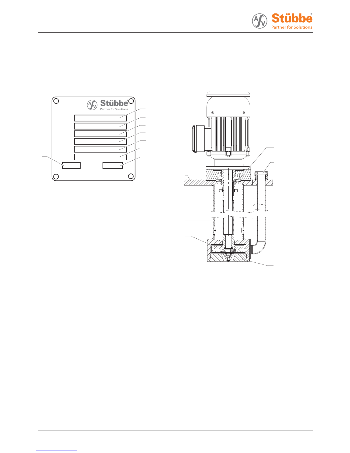
3.1.1 Name plate
Typ:
Ser. NO.:
ID. NO.:
M. Seal:
Imp. Ø: m3/h H: m
Q:
Mat.:
Hollwieser Str. 5
D-32602 Vlotho
1
2
3
4
5
6
87
Fig. 1 Name plate (example)
1Pumptype
2 Serial number
3 Ident. number
4 Housing / sealing material
5 Shaft seal information
6 Impeller diameter [mm]
7 Differential head
8Flow
3.2 Description
Non self-priming, vertical centrifugal pump in modular design.
Useinopenorclosedunpressuredcontainersorpits/trenches.
The pump is dry-running safe.
3.3 Assembly
1
9
8
7
6
5
2
3
4
Fig. 2 Assembly
1 Motor
2 V-ring
3 Discharge Àange
4 Volute casing
5Impeller
6 Immersion tube
7Protectiontube
8Shaft
9Soleplate
8 ETLB-S, ETLB-ST BA-2018.01.25 EN 301 356

Transport, storage and disposal
4 Transport, storage and disposal
4.1 Transport
The user/owner is responsible for the transport of the
pump.
Weight speci¿cations (ĺdocuments for the particular
order)
4.1.1 Unpacking and inspection on delivery
1. Unpack the pump/pump assembly upon delivery and
inspect it for transport damage.
2. Check completeness and accuracy of delivery.
3. Ensure that the information on the name plate agrees with
the order/design data.
4. Report any transportation damage to the manufacturer
immediately.
5. Dispose of packaging material according to local regula-
tions.
Retain the transport frame for horizontal storage (recom-
mended).
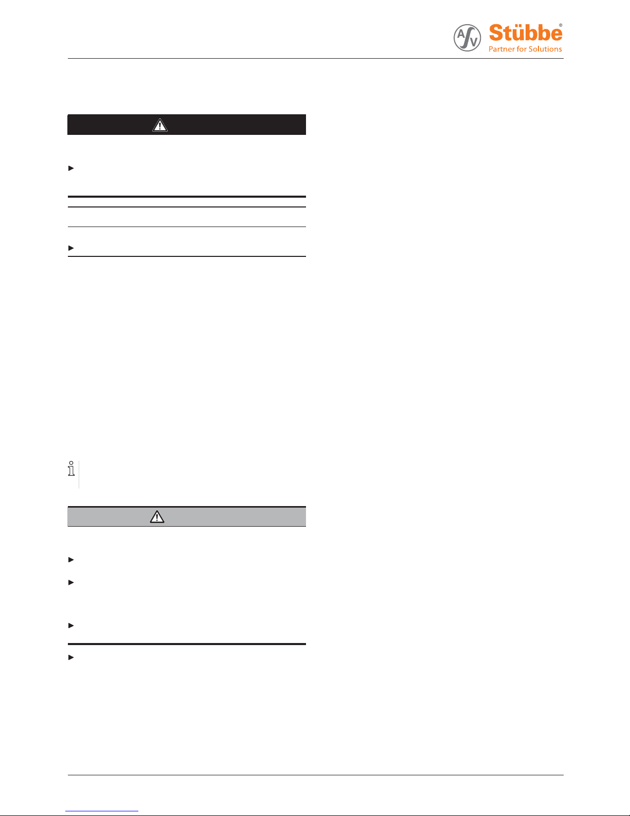
4.1.2 Lifting
DANGER
Death or limbs crushed as a result transported items
falling over!
Use lifting gear appropriate for the total weight to be trans-
ported.
Attach lifting gear in accordance with the following dia-
grams.
Never use the lifting eye of the motor as the attachment
point for lifting the entire pump (the lifting eye of the motor
may be used for securing a pump assembly with a high
center of gravity against being knocked over).
Do not stand under suspended loads.
Fig. 3 Attaching lifting gear to the pump unit
1. Attach lifting gear in accordance with the above diagram.
2. Lift the pump/pump assembly appropriately.
301 356 BA-2018.01.25 EN ETLB-S, ETLB-ST 9
Transport, storage and disposal
4.2 Storage
DANGER
Death or limbs crushed as a result of the pump overturn-
ing!
For vertical storage:
– Place pump on a horizontal underground and secure
against overturning.
NOTE
Material damage due to inappropriate storage!
Store the pump properly.
1. Seal all openings with blind Àanges, blind plugs or plastic
covers.
2. Make sure the storage room meets the following condi-
tions:
–Dry
– Frost-free
– Vibration-free
–UVprotected
3. For horizontal storage:
– Protect pump against sagging by means of proper sup-
port.
4. Rotate the pump shaft twice a month.
5. Make sure the shaft and bearing change their rotational
position in the process.
4.3 Disposal
Plastic parts can be contaminated by poisonous or radioac-
tive pumped liquids to such an extent that cleaning will be
insuf¿cient.
WARNING
Risk of poisoning and environmental damage by the
pumped liquid or oil!
Use personal protective equipment when carrying out any
work on the pump.
Prior to the disposal of the pump:
– Collect and damage any escaping pumped liquid or oil
in accordance with local regulations.
– Neutralize residues of pumped liquid in the pump.
Remove plastic parts and damage them in accordance with
local regulations.
Dispose of the pump in accordance with local regulations.
10 ETLB-S, ETLB-ST BA-2018.01.25 EN 301 356
Setup and connection
5 Setup and connection
NOTE
Material damage due to distortion or passage of electrical
current in the bearing!
Do not make any structural modi¿cations to the pump
assembly or pump casing.
Do not carry out any welding work on the pump assembly
or pump casing.
NOTE
Material damage caused by dirt!
Do not remove the transport seals until immediately before
installing the pump.
Do not remove any covers or transport and sealing covers
until immediately before connecting the pipes to the pump.
5.1 Preparing for installation
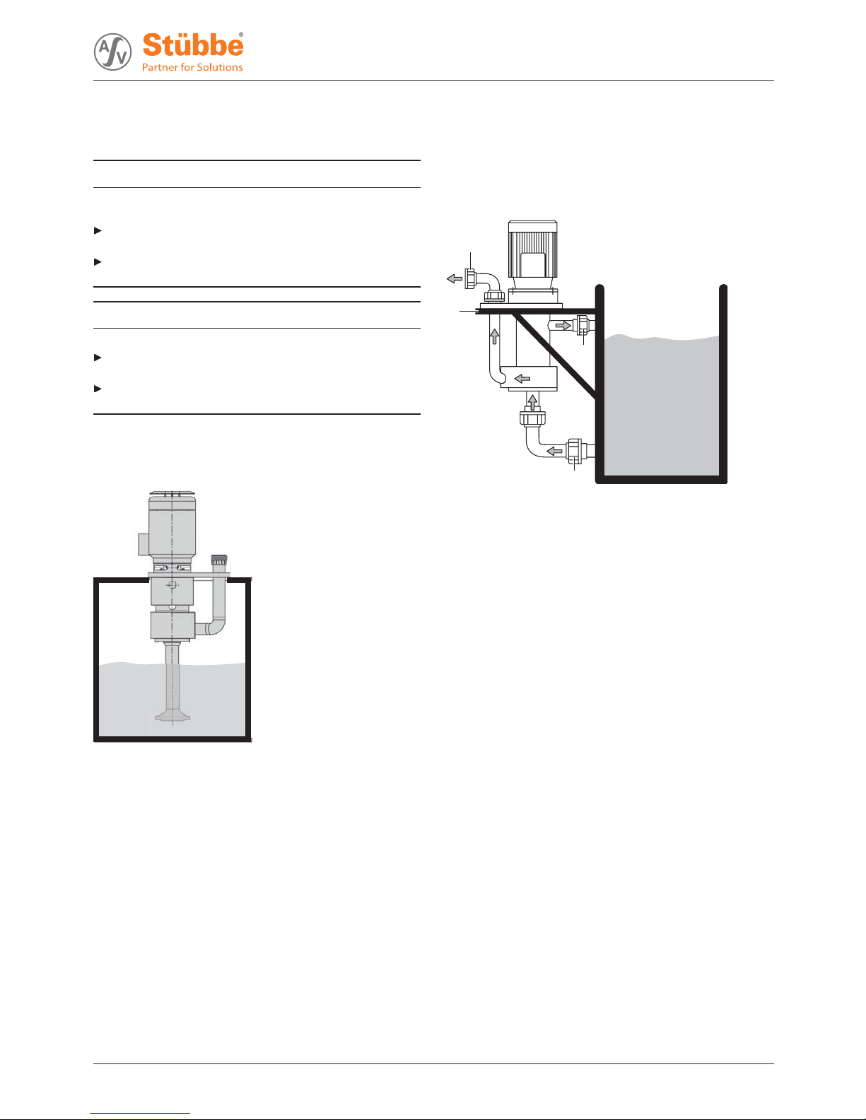
5.1.1 Checking the operating conditions for the ETLB-S
Fig. 4 Mounting the ETLB-S pump on containers
(example with suction extension)
1. Ensure the required operating conditions are met:
– Resistance of body and seal material to the medium
(ĺResistance lists).
– Required ambient conditions
(ĺ9.2.1 Ambient conditions, Page 31).
2. Ensure necessary dimensions for tank cut-out (ĺdata
sheet).
3. Ensure safe aeration and venting of the container in all
operating phases.
4. Ensure the required installation dimensions and ¿lling lev-
els are satis¿ed (ĺdata sheet).
– Minimum distances
–Maximum¿lling height
–Minimum¿lling height
5.1.2 Checking the operating conditions for
the ETLB-ST
1
3
2
4
Fig. 5 Mount the ETLB-ST pump on a supporting structure
1 Process connector on the pressure side
2 Supporting structure
3 Overrun/return of rising medium in the suspension pipe
4 Suction pipe/inlet to pump
1. Ensure the required operating conditions are met:
– Resistance of body and seal material to the medium
(ĺresistance lists).
– Required ambient conditions
(ĺ9.2.1 Ambient conditions, Page 31).
2. Provide an appropriate supporting structure with the
required dimensions for the pump support
(ĺdata sheet). Guarantee the following conditions for the
supporting structure:
– Level and horizontal
– Clean (no oil, dust or other impurities)
– Capable of bearing the weight of the pump assembly
and all operating forces
– Stability of the pump ensured
– Resonance-free
3. Ensure safe aeration and venting of the container in all
operating phases.
4. Ensure the required installation dimensions and ¿lling lev-
els are satis¿ed (ĺdata sheet).
– Minimum distances
–Maximum¿lling height
–Minimum¿lling height
5. Clean containers, basins or pits carefully and protect from
further contamination, e.g. by installing an overÀow con-
tainment wall in front of the container or pit inlet.
301 356 BA-2018.01.25 EN ETLB-S, ETLB-ST 11
Setup and connection
5.1.3 Preparing the installation site
Ensure the installation site meets the following conditions:
– Pump is freely accessible from all sides
–Suf¿cient space for the installation/removal of the pipes
and for maintenance and repair work, especially for the
removal and installation of the pump and the motor
– Pump not exposed to external vibration (damage to
bearings)
– No corrosive exposure
– Frost protection
5.1.4 Surface preparation
Aids, tools, materials:
– Spirit level
1. Make sure the surface meets the following conditions:
– Level and horizontal
– Clean (no oil, dust or other impurities)
– Capable of bearing the weight of the pump assembly
and all operating forces
– Stability of the pump ensured
– Resonance-free
2. Clean containers, basins or pits carefully and protect from
further contamination, e.g. by installing overÀow wall in
front of the container or pit inlet.
5.2 Setting up
1. Remove the suction-side cover if present.
2. Lift pump/pump assembly (ĺ4.1 Transport, Page 9 ).
3. Place pump/pump assembly on the contact surface of the
container/pit.
4. Attach sole plate to the contact surface.
– Pump must not be mechanically under stress as a
result of being attached
5. Screw on the sole plate (ĺ9.2.2 Sole plate tightening
torques, Page 31).
5.3 Planning pipelines
Water hammer may damage the pump or the system. Plan
the pipes and ¿ttings as far as possible to prevent water
hammer occurring.
5.3.1 Specifying supports and Àange connections
NOTE
Material damage due to excessive forces and torques on
the pump.
Ensure pipe connection without stress.
1. Plan pipes safely:
– No pulling or thrusting forces
– No bending moments
– Adjust for changes in length due to temperature
changes (compensators, expansion shanks)
– Optional installation position
2. Support pipes in front of the pump.
3. Ensure the pipe supports have permanent low-friction
properties and do not seize up due to corrosion.
5.3.2 Specifying nominal widths
Keep the Àow resistance in the pipes as low as possible.
1. Make sure the suction extension is not smaller than the
nominal width of the suction branch.
2. Make sure the nominal pressure line width is not smaller
than the nominal discharge Àange width.
–EnsuretheÀow velocity is less than 3 m/s.
5.3.3 Optimizing changes of cross section and
direction
1. Avoid radii of curvature of less than 1.5 times the nominal
pipe diameter.
2. Avoid abrupt changes of cross-section along the piping.
5.3.4 Providing safety and control devices
(recommended)
Avoid reverse running
1. Install a non-return valve between the discharge Àange and
stop valve, to ensure that the medium does not Àow back
after the pump is switched off.
2. In order to enable venting, include vent connection
between discharge Àanges and non-return valve.
Make provisions for isolating and shutting off the pipes
For maintenance and repair work.
Provide shut-off devices in the pressure pipe.
Allow measurements of the operating conditions
1. Provide a pressure gauge in the pressure line for pressure
measurement.
2. Provide pressure measurement on the pump side.
12 ETLB-S, ETLB-ST BA-2018.01.25 EN 301 356
Setup and connection
5.4 Fitting the accessory part
5.4.1 Preparing the accessory part
1. Unpack the accessory part when received and inspect it for
transportation damage.
2. Report any transportation damage to the manufacturer
immediately.
3. For immediate installation, damage packaging material
according to local regulations. If installation is not to be
performed until a later time, leave the accessory part in its
original packaging.
5.4.2 Checking the operating conditions for
the accessory part
1. Ensure the necessary installation dimensions and ¿lling
level of the pump with the accessory part installed (ĺdata
sheet):
– Minimum distances
–Maximum¿lling height
–Minimum¿lling height
2. Ensure that the substrate or container can take the weight
of the pump bearing the accessory part.
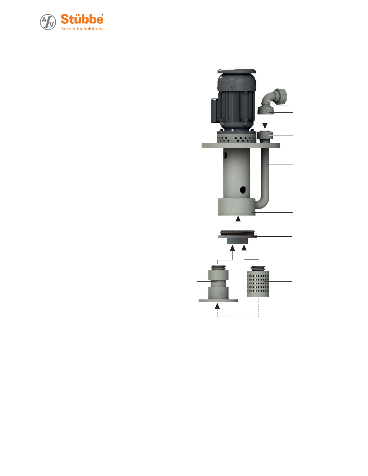
5.4.3 Fitting the accessory part
1
2
3
4
5
6
7
8
Fig. 6 Installation of accessory parts
1 Discharge elbow / Àange adapter
2 Union nut
3 Union nut
4 Discharge Àange
5 Volute casing
6 Adapter
7 Suction strainer
8 Suction extension
301 356 BA-2018.01.25 EN ETLB-S, ETLB-ST 13
Setup and connection
Installing a suction extension and suction strainer
If required the suction extension or the suction strainer can
be installed in the adapter. Optionally the suction strainer
can be installed in the suction extension.
Accessory part prepared
Operating conditions for the accessory part checked
Tool and material:
– Face wrench (125/6 AF)
1. Using the face wrench, unscrew the volute casing cover
clockwise from the volute casing (5). Note this is a left-hand
thread.
2. Using the face wrench, screw the adapter (6) ¿nger-tight
into the left-hand thread of the volute casing (5). In doing
so, ensure the following:
– The sealing ring is positioned correctly
– Do not install the sealing ring dry
3. Depending on the installation situation, proceed as follows:
– When installing the suction extension (8): screw the
suction extension (8) ¿nger-tight into the adapter (6).
Note this is a right-hand thread.
– If necessary, screw the suction strainer (7) ¿nger-tight
into the suction extension (8).
–OR–
– When installing the suction strainer (7): screw the suc-
tion strainer (7) ¿nger-tight into the adapter (6). Note
this is a right-hand thread.
Installing the discharge elbow / Àange adapter
Accessory part prepared
Operating conditions for the accessory part checked
1. Unscrew the union nut (3) from the discharge Àange (4). If
necessary, remove the insert from the discharge Àange (4).
2. Position the discharge elbow / Àange adapter (1) on the
discharge Àange (4) and align it.
3. Using the union nuts (2), bolt the discharge elbow / Àange
adapter (1) ¿nger-tight to the discharge Àange (4).
5.5 Connecting the pipes
NOTE
Material damage due to excessive forces and torques on
the pump.
Ensure pipe connection without stress.
5.5.1 Keeping the piping clean
NOTE
Material damage due to impurities in the pump!
Make sure no impurities can enter the pump.
1. Clean all piping parts and ¿ttings prior to assembly.
2. Flush all pipes carefully with neutral medium.
3. Ensure no Àange seals protrude inwards.
4. Remove any blind Àanges, plugs, protective foils and/or
protective paint from the Àanges.
5.5.2 Installing the pressure pipe
1. Remove the transport and sealing covers from the pump.
2. Fit the pressure line stress-free and sealed
3. Ensure no seals protrude inwards.
5.5.3 Inspection for stress-free pipe connections
Piping installed and cooled down
1. Disconnect the pipe connecting Àanges from the pump.
2. Check whether the pipes can be moved freely in all direc-
tions within the expected range of expansion:
– Nominal width < 150 mm: by hand
– Nominal width > 150 mm: with a small lever
3. Make sure the Àange surfaces are parallel.
4. Reconnect the pipe connecting Àanges to the pump.
5. If present, check support foot for stress.
14 ETLB-S, ETLB-ST BA-2018.01.25 EN 301 356

Setup and connection
5.6 Electrical connection
DANGER
Risk of electrocution!
All electrical work must be carried out only by quali¿ed elec-
tricians.
Before all work on the electrical system, disconnect the
motor from the mains and secure against being switched
back on again.
5.6.1 Connecting the motor
Follow the instructions of the motor manufacturer.
1. Connect the motor according to the connection diagram.
2. Make sure no danger arises due to electric power.
3. Install an EMERGENCY STOP switch.
5.6.2 Connecting the thermistor
2TP1
2TP2
2TP1 2TP2
Connect the PTC thermistor to the motor protector.
– Activation temperature 155°C
– Test voltage 2.5 V
5.6.3 Check direction of rotation
DANGER
Danger to life from rotating parts.
Use personal protective equipment when carrying out any
work on the pump.
Maintain an adequate distance from rotating parts.
1. Switch on motor for max. 2 seconds and switch it off again
immediately.
2. Check whether the sense of rotation of the motor matches
the direction of rotation on the fan impeller.
3. If the sense of rotation is different: Change over any two
phases.
5.7 Performing the hydrostatic test
Only necessary if the entire system needs to be tested
under pressure.
NOTE
Material damage due to bursting of pump casing.
Testing pressure must not exceed the permissible pump
pressure (ĺdocuments for the particular order).
Make sure the testing pressure does not exceed the per-
missible pump pressure.
– If necessary, do not perform pressure test on the pump.
301 356 BA-2018.01.25 EN ETLB-S, ETLB-ST 15

Operation
6Operation
6.1 Preparing for commissioning
6.1.1 Check downtimes
Check downtimes (ĺ6.4 Restoring the pump to service,
Page 18).
6.1.2 Filling and bleeding
WARNING
Risk of injury and poisoning due to hazardous pumped
liquids!
Use protective equipment for any work on the pump.
Collect leaking liquid safely and damage ¿tting in accor-
dance with local regulations.
1. Close the pressure-side ¿tting.
2. Fill pump and, if present, suction pipe with Àuid.
Ensure minimum ¿lling height when doing so
3. Verify that no pipe connections are leaking.
6.2 Commissioning
6.2.1 Switching on
Pump set up and connected properly
Motor set up and connected properly
All connections stress-free and sealed
All safety equipment installed and tested for functionality
Pump prepared, ¿lled and vented correctly
Container is ¿lled suf¿ciently up to minimum height “Z”
(ĺ9.2.4 Filling heights and installation dimensions,
Page 31).
DANGER
Risk of injury due to running pump!
Do not touch the pump when it is running.
Do not carry out any work on the pump when it is running.
Allow the pump to cool down completely before starting any
work.
DANGER
Risk of injury and poisoning due to pumped liquid spray-
ing out!
Use personal protective equipment when carrying out any
work on the pump.
NOTE
Risk of cavitation if suction Àow is restricted!
Open the suction-side ¿tting and do not use it to regulate
the Àow.
Do not open the pressure-side ¿tting beyond the operating
point.
NOTE
Material damage due to overheating.
Do not operate the pump for long periods with the pressure-
side ¿tting closed.
Observe minimum Àow (ĺorder data sheet).
1. Open the suction-side ¿tting.
2. Close the pressure-side ¿tting.
3. Switch on the motor and check it for smooth running.
4. Once the motor has reached its nominal speed, open
the pressure-side ¿tting slowly until the operating point is
reached.
5. Make sure temperature change is smaller than 5 K/min for
pumps with hot Àuids.
6. After the initial stress due to the pressure and operating
temperature, check that the pump is not leaking.
16 ETLB-S, ETLB-ST BA-2018.01.25 EN 301 356
Operation
6.2.2 Switching off
Pressure-side ¿tting closed (recommended)
WARNING
Risk of injury due to hot pump parts!
Use personal protective equipment when carrying out any
work on the pump.
1. Switch off motor.
2. Check all connecting bolts and tighten them if necessary
(only after initial commissioning).
6.3 Shutting down the pump
DANGER
Risk of injury due to running pump!
Do not touch the pump when it is running.
Do not carry out any work on the pump when it is running.
Before all installation and maintenance work, disconnect
the motor from the mains and secure it against being
switched back on again.
DANGER
Risk of electrocution!
All electrical work must be carried out only by quali¿ed elec-
tricians.
Before all work on the electrical system, disconnect the
motor from the mains and secure against being switched
back on again.
WARNING
Risk of injury and poisoning due to hazardous pumped
liquids!
Use protective equipment for any work on the pump.
Collect leaking liquid safely and damage ¿tting in accor-
dance with local regulations.
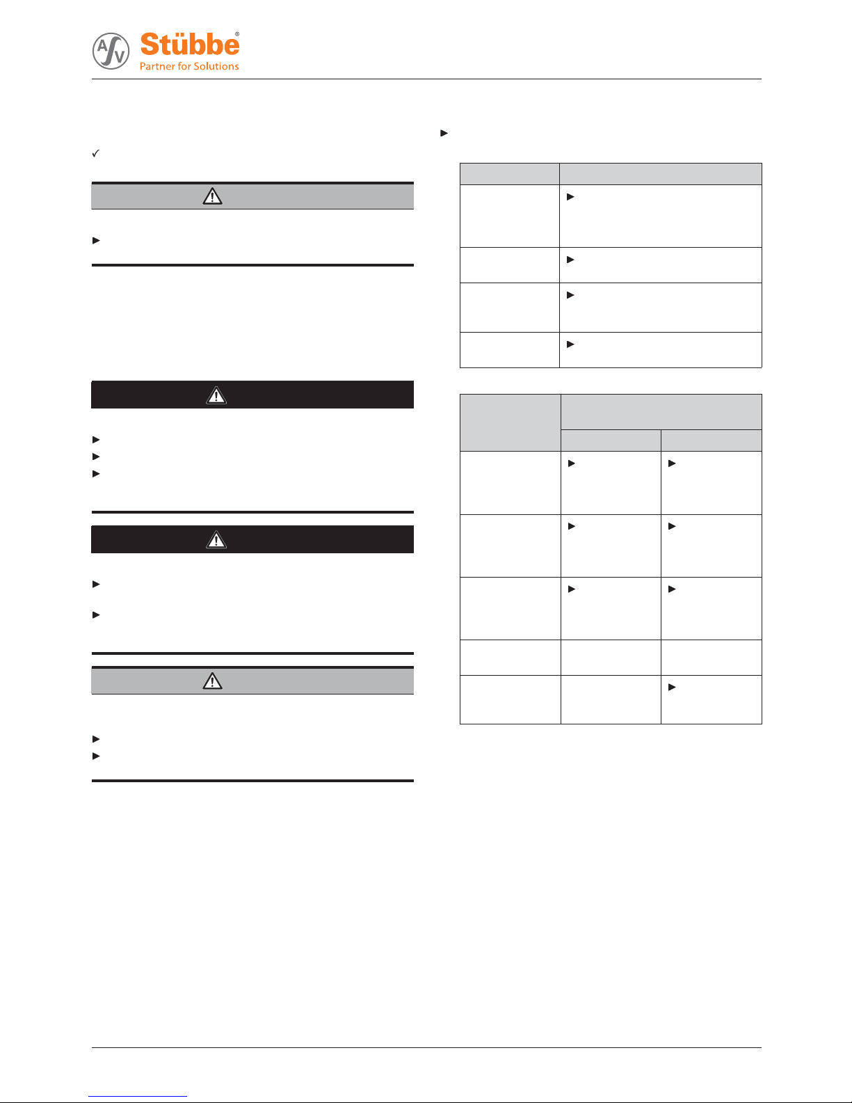
Take the following measures whenever the pump is shut
down:
Pump is Action
shut down Take measures appropriate for
the Àuid (ĺTable 4 Measures
depending on the behavior of
the pumped liquid, Page 17).
…emptied Close suction and pressure-side
¿tting.
…dismounted Isolate the motor from its power
supply and secure it against
unauthorized switch-on.
…put into
storage
Note measures for storage.
Tab. 3 Measures to be taken if the pump is shut down
Duration of shutdown (depending
on process)
Behavior of the
pumped liquid
Short Long
Crystallized or
polymerized,
solids
sedimenting
Flush the
pump.
Flush the
pump.
Solidifying/
freezing,
non-corrosive
Heat up or
empty the
pump and
containers.
Empty the
pump and
containers.
Solidifying/
freezing,
corrosive
Heat up or
empty the
pump and
containers.
Empty the
pump and
containers.
Remains liquid,
non-corrosive
––
Remains liquid,
corrosive
–Empty the
pump and
containers.
Tab. 4 Measures depending on the behavior
of the pumped liquid
301 356 BA-2018.01.25 EN ETLB-S, ETLB-ST 17

Operation
6.4 Restoring the pump to service
1. Complete all steps as for commissioning
(ĺ6.2 Commissioning, Page 16).
2. If the pump is shut down for over 1 year, replace elastomer
seals (O-rings, shaft sealing rings).
6.5 Operating the stand-by pump
Stand-by pump ¿lled and bled
Operate the stand-by pump at least once a week.
Open pressure-side ¿tting far enough so that the stand-by
pump operating temperature is achieved and heating is
even (ĺ6.2.1 Switching on, Page 16).
18 ETLB-S, ETLB-ST BA-2018.01.25 EN 301 356
Maintenance
7 Maintenance
Trained service technicians are available for ¿tting and
repair work. Submit evidence of conveyed medium on
request (DIN safety data sheet or safety certi¿cate).
7.1 Inspections
The inspection intervals depend on the operational strain
on the pump.
DANGER
Risk of injury due to running pump!
Do not touch the pump when it is running.
Do not carry out any work on the pump when it is running.
WARNING
Risk of injury and poisoning due to hazardous pumped
liquids!
Use protective equipment for any work on the pump.
1. Check at appropriate intervals:
– Adherence to the minimum Àow rate
– Normal operating conditions unchanged
– Filling level of the container
2. For trouble-free operation, always ensure the following:
–Noleaks
– No cavitation
– Free and clean ¿lters
– No unusual running noises or vibrations
– No inadmissible leaks on the shaft seal
7.2 Servicing
Operating life of antifriction bearings in operation are within
permissible range: >2 years.
Intermittent operation, high temperatures, low viscosities
and aggressive ambient and process conditions reduce the
service life of antifriction bearings.
Plain bearings are subject to natural wear and tear which
is heavily dependent on the respective operating condi-
tions. It is therefore not possible to make general state-
ments about the operating life.
DANGER
Risk of injury due to running pump!
Do not touch the pump when it is running.
Do not carry out any work on the pump when it is running.
Before all installation and maintenance work, disconnect
the motor from the mains and secure it against being
switched back on again.
DANGER
Risk of electrocution!
All electrical work must be carried out only by quali¿ed elec-
tricians.
Before all work on the electrical system, disconnect the
motor from the mains and secure against being switched
back on again.
WARNING
Risk of injury and poisoning due to hazardous or hot Àuid!
Use protective equipment for any work on the pump.
Allow the pump to cool down completely before commenc-
ing any work.
Make sure the pump is depressurized.
Empty the pump, safely collect the pumped liquid and dam-
age it in accordance with environmental rules and require-
ments.
7.2.1 Maintenance in accordance with main-
tenance schedule
Perform maintenance work in accordance with the mainte-
nance schedule (ĺ9.3 Maintenance schedule, Page 32).
7.2.2 Cleaning the pump
NOTE
High water pressure or spray water can damage bearings!
Do not clean bearing areas with a water or steam jet.
Clean large-scale grime from the pump.
301 356 BA-2018.01.25 EN ETLB-S, ETLB-ST 19
Maintenance
7.3 Dismounting
DANGER
Risk of injury due to running pump!
Do not touch the pump when it is running.
Do not carry out any work on the pump when it is running.
Before all installation and maintenance work, disconnect
the motor from the mains and secure it against being
switched back on again.
DANGER
Risk of electrocution!
All electrical work must be carried out only by quali¿ed elec-
tricians.
Before all work on the electrical system, disconnect the
motor from the mains and secure against being switched
back on again.
DANGER
Death or limbs crushed as a result of the pump overturn-
ing.
Place pump on a horizontal underground and secure
against overturning.
WARNING
Risk of injury and poisoning due to hazardous or hot Àuid!
Use protective equipment for any work on the pump.
Allow the pump to cool down completely before commenc-
ing any work.
Make sure the pump is depressurized.
Empty the pump, safely collect the pumped liquid and dam-
age it in accordance with environmental rules and require-
ments.
WARNING
Risk of injury due to heavy components!
Pay attention to the component weight. Lift and transport
heavy components using suitable lifting gear.
Set down components safely and secure them against
overturning or rolling away.
WARNING
Risk of injury during disassembly!
Secure the pressure-side gate valve against accidental
opening.
Depressurize the blocking pressure system, if available.
Wear protective gloves, components can become very
sharp-edged due to wear or damage.
Remove spring-loaded components carefully (e.g.
mechanical seal, stressed bearing, valves etc.), as com-
ponents can be ejected by the spring stress.
Observe the manufacturer's speci¿cations (e.g. for the
motor, coupling, mechanical seal, blocking pressure sys-
tem, cardan shaft, drives, belt drive etc.).
NOTE
Material damage due to incorrect dismounting/installation
of the pump.
Only specialist mechanics should complete dismounting/
installation work.
7.3.1 Preparations for dismounting
Pump is depressurized
Pump completely empty, Àushed and decontaminated
Electrical connections disconnected and motor secured
against switch-on
Pump cooled down
Pressure gauge lines, pressure gauge and ¿xtures dis-
mounted
When dismounting, observe the following:
– Mark the precise orientation and position of all compo-
nents before dismounting them.
– Dismount components concentrically without canting.
– Dismount pump (ĺsectional drawing).
20 ETLB-S, ETLB-ST BA-2018.01.25 EN 301 356
This manual suits for next models
1
Table of contents
Other Stübbe Water Pump manuals


Popular Water Pump manuals by other brands

Little Giant
Little Giant 8E-CIA-RFS manual

red lion
red lion 6RLAG-2LST owner's manual

Little Giant
Little Giant 9SC Series owner's manual

ThePondguy
ThePondguy Water Garden Aeration Kit installation manual

New Era Pump Systems
New Era Pump Systems 9000 Series user manual

aqua technix
aqua technix Aqua Mini 3 Installation and operating instructions


Powerplus
Powerplus POWX1710 instruction manual

ActiveAqua
ActiveAqua AAPC1020 user manual

Little Giant
Little Giant Eliminator Series manual

Delta
Delta Dual V4 installation instructions

FLORABEST
FLORABEST FTP 400 B2 translation of original operation manual

Equalizer
Equalizer HP350S Operator's instruction manual