manuals.online logo
Brands
  1. Home
  2. •
  3. Brands
  4. •
  5. LEGRAND
  6. •
  7. Security Sensor
  8. •
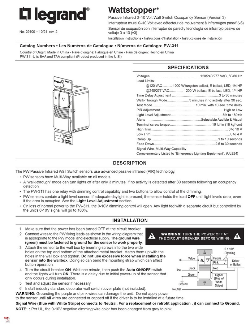
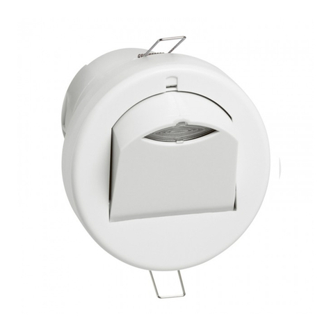
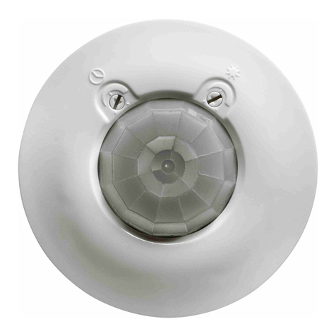
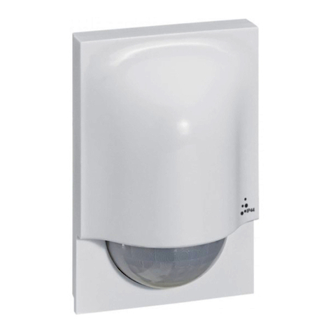
  9. LEGRAND 0 648 75 User manual

LEGRAND 0 648 75 User manual

x1
2 AA batteries
2 x AA - 1,5 V
+ 5° C / + 45° C
PIR
2 - 8 m
5 à 1000 LUX
de 15 s à 15 min
IP 44
Pack contents
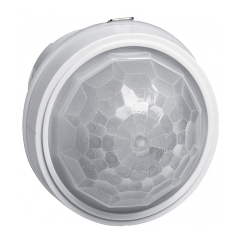
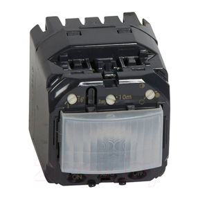
Wireless motion sensor
This product is a connected accessory which requires you to buy and install the «... with
Netatmo» connected starter pack and «... with Netatmo» connected power outlets, swit-
ches (with dimmer option) and/or connected lighting micromodules rst.
Specifications
This product can control up to 20
connected switches (with dimmer option),
micromodules, cable outlets and power
outlets «... with Netatmo»
Frequency bands: 2.4 - 2.4835 GHz
Power level: <10mW
Wireless motion sensor
0 648 75
LE11418AA



Do not x the motion sensor to the wall now.
The installation will be nalized on step 6.
Do not insert the batteries now
Start the wireless motion sensor configuration
Press the middle of the wireless master switch until its light briey turns green,
and then stop pressing. The indicator lights on the products which you have wired will
turn green.
Open the front cover
2




The motion sensor light will ash
green and then switch o.
Nota : if the motion sensor ashes green green red, then remove the batteries and
restart on Step 2
Insert the batteries in the wireless motion sensor
A
B
C
D
Make sure that the indicator lights on the wired products are green and not
ashing. If not, go back to step 2 and then comme back to step 4.
Pair the wireless motion sensor to a wired connected product
To pair a wireless motion sensor with a connected light switch, go to step 4.1.1
To pair a wireless motion sensor with a connected micromodule, go to step 4.2.1
To pair a wireless motion sensor with a connected power outlet, go to step 4.3.1
Phase A : Press the ON button on the wireless switch you wish to pair, while tapping it three
times onto the light switch you wish to control.
Phase B : The indicator lights on the two products will ash blue rapidly.
Phase C : The indicator lights on the two products will briey turn blue and stop ashing
Phase D : the light on the wired product will turn green again and the light on the wireless
motion sensor will switch o. The pairing was successful.
4
4.1.1 Pair a wireless motion sensor with a connected light switch

B
A
D
C
Press the ON and OFF buttons of the wireless motion
sensor to check if the light turns on and o correctly. If it
doesn’t, come back to step 4.1.1.
4.2.1 Pair a wireless motion sensor with a connected micromodule
Phase A : Press the ON button on the wireless switch you wish to pair, while tapping it
three times onto the micromodule you wish to control.
Phase B : The indicator lights on the two products will ash blue rapidly.
Phase C : The indicator lights on the two products will briey turn blue and stop ashing
Phase D : the light on the wired product will turn green again and the light on the wireless
motion sensor will switch o.
4.1.2 Check the correct pairing
5
D
B
A C
4.3.1 Pair a wireless motion sensor with a connected power outlet
Phase A : Press the ON button on the wireless switch you wish to pair, while tapping it three
times onto the power outlet you wish to control.
Phase B : The indicator lights on the two products will ash blue rapidly.
Phase C : The indicator lights on the two products will briey turn blue and stop ashing
Phase D : the light on the wired product will turn green again and the light on the wireless
motion sensor will switch o.
Press the ON and OFF buttons of the wireless motion
sensor to check if the light turns on and o correctly. If it
doesn’t, come back to step 4.1.1
4.1.2 Check the correct pairing
6
Multiple pairing
You can control several connected switches, micromodules and power outlets by repeating
the step 4 on each product you wish to control.
Complete the configuration
To complete your installation,
briefly press the middle of thewireless master switch.
All the indicator lights on the products switch off.
7
60 mm
Ø 3,5 mm maxi
Ø 6,5 mm
2,5
10
m60
6
10
m6
Recommended places
Fix the motion sensor
For optimal use, the motion detector should be placed at a height of approximately 2.50
m from the ground.
8
To increase the time that the
associated product remains
ON (eg, light), turn the screw
(potentiometer) clockwise.
Set up the motion sensor
Time delay
Ambient light sensitivity
Movement sensitivity
8.1 Adjust the ambient light sensitivity
9
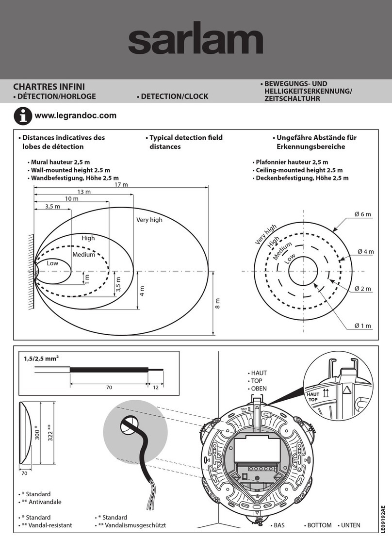
By default, the motion detector is set to a minimum delay (15 seconds), a maximum
light sensitivity (1000 lux) and a maximum sensor sensitivity (8 meters). If you want
to change these settings, fol-
low the steps below.
8.2 Adjust the ambient light sensitivity
8.3 Adjust the motion sensor sensitivity
In order for the sensor to detect only when it is dark, turn the screw (potentiometer)
counterclockwise.
To reduce the sensitivity of the motion sensor, turn the screw (potentiometer)
counterclockwise. The detection will then be at a shorter distance.
10
LEGRAND - Pro and Consumer Service - BP 30076
87002 LIMOGES CEDEX FRANCE • www.legrand.com
www.legrand.fr
Close the front cover
To add a connected product to your connected installation,
you should follow the instructions :
- in the Legrand Home + Control application (Settings/Add a new product section)
- or consult the user manual on legrand.fr
11










Red led light : low
battery (*)
(*) 2 years batteries lifetime for 50
detections per day with a time delay of
3 minutes
SIMPLIFIED EU DECLARATION OF CONFORMITY
The undersigned,
Legrand
declares that the radio-electric equipment referred to in these instructions complies with directive 2014/53/EU.
The full text of the EU declaration of conformity
is available on the following website :
www.legrandoc.com
Batteries replacement

Other LEGRAND Security Sensor manuals

LEGRAND 845 02 User manual

LEGRAND

LEGRAND 845 02 User manual

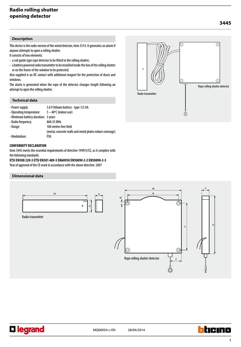
LEGRAND 3445 User manual

LEGRAND

LEGRAND 3445 User manual

LEGRAND WattStopper LMUC-100-2 User manual

LEGRAND

LEGRAND WattStopper LMUC-100-2 User manual

LEGRAND 088230 User manual

LEGRAND

LEGRAND 088230 User manual

LEGRAND Wattstopper DW-100-B User manual

LEGRAND

LEGRAND Wattstopper DW-100-B User manual

LEGRAND 048822 User manual

LEGRAND

LEGRAND 048822 User manual

LEGRAND CP Electronics EBMHS-BLV User manual

LEGRAND

LEGRAND CP Electronics EBMHS-BLV User manual

LEGRAND Tynetec ZXT424 User manual

LEGRAND

LEGRAND Tynetec ZXT424 User manual

LEGRAND 431 42 User manual

LEGRAND

LEGRAND 431 42 User manual

LEGRAND 0 489 55 User manual

LEGRAND

LEGRAND 0 489 55 User manual

LEGRAND EMOS G1180 User manual

LEGRAND

LEGRAND EMOS G1180 User manual

LEGRAND Celiane Series User manual

LEGRAND

LEGRAND Celiane Series User manual

LEGRAND 0 488 17 Instruction Manual

LEGRAND

LEGRAND 0 488 17 Instruction Manual

LEGRAND CP Electronics EBDHS-KNX User manual

LEGRAND

LEGRAND CP Electronics EBDHS-KNX User manual

LEGRAND CP Electronics MWS3A-AT-DD User manual

LEGRAND

LEGRAND CP Electronics MWS3A-AT-DD User manual

LEGRAND Mosaic 0 489 22 User manual

LEGRAND

LEGRAND Mosaic 0 489 22 User manual

LEGRAND 0 672 26 User manual

LEGRAND

LEGRAND 0 672 26 User manual

LEGRAND Celiane 670 92 User manual

LEGRAND

LEGRAND Celiane 670 92 User manual

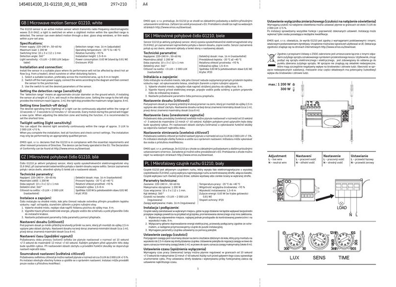
LEGRAND EMOS G1210 User manual

LEGRAND

LEGRAND EMOS G1210 User manual

LEGRAND Wattstopper LMDC-100 User manual

LEGRAND

LEGRAND Wattstopper LMDC-100 User manual

LEGRAND Pass & Seymour WDT301 User manual

LEGRAND

LEGRAND Pass & Seymour WDT301 User manual

LEGRAND EMOS G1110 User manual

LEGRAND

LEGRAND EMOS G1110 User manual

LEGRAND 6 460 03 User manual

LEGRAND

LEGRAND 6 460 03 User manual

LEGRAND EMOS G1130 User manual

LEGRAND

LEGRAND EMOS G1130 User manual

Popular Security Sensor manuals by other brands

biosystems Toxi Plus Reference manual

biosystems

biosystems Toxi Plus Reference manual

PROEM CIR10 Installation Notice

PROEM

PROEM CIR10 Installation Notice

Werner A510000 instruction manual

Werner

Werner A510000 instruction manual

Teknim TFD-3250 Installation & operating guide

Teknim

Teknim TFD-3250 Installation & operating guide

PCB Piezotronics ICP 121A41 Installation and operating manual

PCB Piezotronics

PCB Piezotronics ICP 121A41 Installation and operating manual

Fracarro DT1000AM quick start guide

Fracarro

Fracarro DT1000AM quick start guide

bureau veritas EcotestVIP operating manual

bureau veritas

bureau veritas EcotestVIP operating manual

Buchi Alltech 3300 ELSD Operation manual

Buchi

Buchi Alltech 3300 ELSD Operation manual

Honeywell PROINDMV Installation and setup guide

Honeywell

Honeywell PROINDMV Installation and setup guide

Visonic SPY 1 installation instructions

Visonic

Visonic SPY 1 installation instructions

Lince GR868 Bobby Technical manual

Lince

Lince GR868 Bobby Technical manual

CIAS Elettronica S.r.l. Murena installation manual

CIAS Elettronica S.r.l.

CIAS Elettronica S.r.l. Murena installation manual

Pepperl+Fuchs NBN8-18GS50-Z4L-V1-3G-3D instruction manual

Pepperl+Fuchs

Pepperl+Fuchs NBN8-18GS50-Z4L-V1-3G-3D instruction manual

Indexa 3000P user manual

Indexa

Indexa 3000P user manual

JB INDUSTRIES LD-6000IR Operator's manual

JB INDUSTRIES

JB INDUSTRIES LD-6000IR Operator's manual

HTS ECO-JackDUAL HT600 user manual

HTS

HTS ECO-JackDUAL HT600 user manual

IFM Electronic Efector500 PF2058 operating instructions

IFM Electronic

IFM Electronic Efector500 PF2058 operating instructions

Atlantis A18-DSD06 manual

Atlantis

Atlantis A18-DSD06 manual

manuals.online logo
manuals.online logoBrands
  • About & Mission
  • Contact us
  • Privacy Policy
  • Terms and Conditions

Copyright 2025 Manuals.Online. All Rights Reserved.