Rockwell Automation Allen-Bradley ASEM 6300 User manual

Installation Instructions
Original Instructions
ASEM 6300 On-Machine Monitors and On-Machine Panel PCs
Catalog Numbers 6300MA, 6300PA
Compliance
UL/cUL Mark Compliance
Equipment with the UL/cUL mark complies with the requirements of UL 61010-1, UL 61010-2-201, CSA C22.2 No. 61010-1, and CSA C22.2 No. 61010-2-201.
A copy of the certificate of compliance is available at rok.auto/certifications.
European Union Directive Compliance
This equipment meets the European Union Directive requirements when installed within the European Union or EEA regions and have the CE marking.
A copy of the declaration of the conformity is available at rok.auto/certifications.
Topic Page
Compliance 1
Product Overview 2
Required Tools and Optional Accessories 2
Approximate Dimensions 2
Environmental Requirements 2
Mounting Requirements 3
Prepare for Installation 3
Installation 4
Connect DC Power 5
Attach Peripheral Cables 6
Mount the On-Machine Product 6
Reattach the Cover 6
Complete the Installation 6
Additional Resources 7
ATTENTION: Read this document and the documents listed in the Additional Resources section about installation, configuration, and operation of this
equipment before you install, configure, operate, or maintain this product. Users are required to familiarize themselves with installation and wiring
instructions in addition to requirements of all applicable codes, laws, and standards.
Activities including installation, adjustments, putting into service, use, assembly, disassembly, safety, and maintenance are required to be carried out
by suitably trained personnel in accordance with applicable code of practice. If this equipment is used in a manner not specified by the manufacturer,
the protection provided by the equipment may be impaired.
ATTENTION: If a SIL-3 E-stop button is used, familiarize yourself with the Safety section in the ASEM™ On-Machine™ User Manual,
publication 6300-UM002.
ATTENTION: This equipment is intended to operate in an industrial or control room environment, which uses some form of power isolation from the
public low-voltage mains. Some computer configurations cannot comply with the EN 61000-3-2 Harmonic Emissions standard as specified by the EMC
Directive of the European Union.
All I/O cables must be used only indoors.

2Rockwell Automation Publication 6300-IN001A-EN-P - June 2023
ASEM On-Machine Monitor and On-Machine Panel PC Installation Instructions
Product Overview
Designed for full IP65 protection grade industrial applications, your ASEM
On-Machine product features:
• Powder coated die-cast aluminum alloy chassis with anti-scratch
treatment
• Aluminum or True Flat aluminum front panel
• Fully configurable button area with hard-wired connection mode which
accommodates an SIL-3 emergency stop (E-stop) button
• Light emitting diode (LED) status indicators
• Resolution up to full high-definition (FHD)
• Bottom arm, top arm, or VESA mounting
VESA (Video Electronics Standards Association) mount, also known as Flat Display Mounting
Interface (FDMI), is a standardized mounting format that makes it easier to select the correct
mount for your product and allows you to mount the product on a wall so that it takes up less
space, or on a movable arm for better ergonomics.
• Microsoft® Windows® 10 IoT Enterprise 2016/2019 64-bit Operating System
• Dual core Intel® Celeron® and Intel Core™ of 7th generation 15W Intel Kaby
Lake Unit Level Traceability (ULT) platform
Required Tools and Optional Accessories
You need the following tools to install and connect your On-Machine product.
• DC power supply (see Power Requirements on page 2)
• Torque limiting screwdriver with 2.5 mm hex key bit
• I/O cables, which are shielded and rated for indoor use
• Wire stripper, cutter, and crimper tool
• Clean, microfiber cloth
• For bottom arm, top arm, or VESA mounting:
- Adapter plate (see publication 6300V-PC005 for proper selection)
- Monitor arm or VESA bracket
• Optional accessories:
- CFast card (for panel PC only)
- Connection terminal buttons and E-stop button for select models with
button area
- Side handles or perimeter handle, and keyboard tray (see publication
6300V-PC005 for ordering information)
Approximate Dimensions
Dimensions that are shown in Table 1 and Table 2 are shown in millimeters
(inches). Dimensions are not intended to be used for manufacturing purposes.
Environmental Requirements
Follow these environment requirements to make sure that your On-Machine
product provides service with excellent reliability
• Your installation site:
- must have sufficient power,
- must be indoors and non-hazardous,
- must not expose your On-Machine product to direct sunlight, and
- must be placed in an industrial or control room environment that uses
some form of power isolation from the public, low voltage mains.
• The surrounding air temperature must not exceed the maximum
temperature for your On-Machine product.
• The ambient air temperature range is:
0…50 °C (32…122 °F) for all processors.
• The surrounding air temperature range for storage is:
-10…+60 °C (14…140 °F).
• The relative humidity of the ambient air must be:
20…90% noncondensing at 0…40 °C (32…104 °F) and
20…80% noncondensing at 41…50 °C (105…122 °F).
Power Requirements
The nominal output power must be 25% larger than the drained power.
• The output voltage rise time has to be less than 100 ms.
• Consider the working temperature and the thermal derating of the power
supply.
• The inrush current cannot exceed a peak current of 10 A and a pulse width
time of 400 μs.
If you will be adding an accessory (such as side handles, perimeter
handle, or keyboard tray), plan for a wider width at your installation
site. See the applicable section in publication 6300-UM001 for
approximate dimensions of your chosen accessories.
Table 1 - Approximate Dimensions by LCD Size [mm (in.)]: Landscape
Dimension 15.6 in. 18.5 in. 21.5 in. 24 in.
A396.30 (15.60) 461.80 (18.18) 528.80 (20.82) 585.2 (23.04)
B245.80 (9.68) 282.60 (11.13) 320.20 (12.61) 352.8 (13.89)
C304.30 (11.98) 341.10 (13.43) 378.70 (14.91) 411.3 (16.19)
D58.50 (2.30) 58.50 (2.30) 58.50 (2.30) 58.50 (2.30)
A
B
A
BC
D
Device Only with Button Area
Button Area
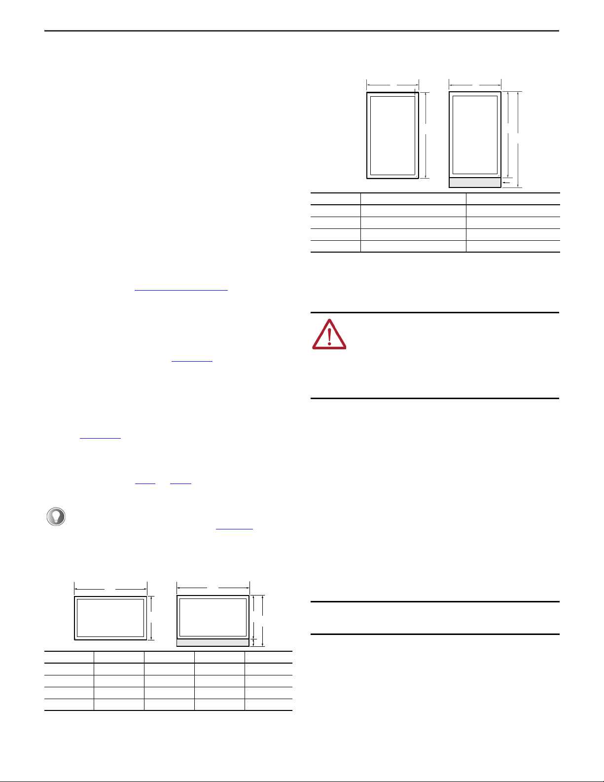
Table 2 - Approximate Dimensions by LCD Size [mm (in.)]: Portrait
Dimension 21.5 in. 24 in.
A320.20 (12.61) 352.80 (13.89)
B528.80 (20.82) 585.20 (23.04)
C587.30 (23.12) 643.90 (25.35)
D58.50 (2.30) 58.70 (2.31)
ATTENTION: This equipment is intended for use in a Pollution
Degree 2 industrial environment, in overvoltage Category II
applications (as defined in IEC 60664-1), at altitudes up to
2000 m (6561 ft) without derating.
This equipment is considered Group 1, Class A industrial
equipment according to IEC/EN 61326-1. Without appropriate
precautions, there can be potential difficulties with
electromagnetic compatibility in other environments due to
conducted as well as radiated disturbance.
IMPORTANT If a non-sufficient power source is used, the initial boot
process can be negatively effected and the operating
system (OS) can cause corruption.
A
C
B
D
A
B
Device Only with Button Area
Button Area

Rockwell Automation Publication 6300-IN001A-EN-P - June 2023 3
ASEM On-Machine Monitor and On-Machine Panel PC Installation Instructions
• The On-Machine product must:
- be connected to a 24V (18…32V) power supply that satisfies the
requirements of safe extra low voltage (SELV) in accordance with
IEC/EN/DIN EN/UL60950-1 and as defined in IEC-61010-2-201, power
supply per UL.
- use an isolated power supply with galvanic isolation to help prevent
common mode noise at low/medium frequencies on the power supply
line, ground loop noise, and overvoltage caused by lightning.
Mounting Requirements
Follow these mounting requirements to mount your On-Machine product:
• Choose a suitable, ergonomic mounting height. See the approximate
dimensions listed in Table 3 or Table 4 to plan the mounting height.
- Approximate dimensions shown in Table 3 and Table 4 are listed in
millimeters (inches). Dimensions are not for manufacturing purposes.
Prepare for Installation
1. Set your On-Machine product with the LCD facing down onto a clean
surface.
2. Use a 2.5 mm torque-limiting screwdriver to remove the M3 screws from
the cover.
3. Set the screws and cover aside. The ground screw, terminal ports, I/O
ports, and slots are now accessible.
Table 3 - Approximate Dimensions by LCD Size [mm (in.)]: Landscape
Bottom or
Top Arm
Mount
Dimension 15.6 in. 18.5 in. 21.5 in. and 24 in.
A65 (2.56) 71 (2.80) 75 (2.95)
B120 (4.72) 126 (4.96) 130 (5.12)
C113.4 (4.46) 113.4 (4.46) 123.9 (4.88)
VESA Mount
Dimension 15.6 in. 18.5 in. 21.5 in. and 24 in.
A65 (2.56) 65 (2.56) 75 (2.95)
B107 (4.21) 113 (4.45) 117 (4.61)
C113.4 (4.46) 113.4 (4.46) 123.9 (4.88)
A
A
A
B
B
B
C
C
C
Bottom Arm Mount Top Arm Mount
VESA Mount
Table 4 - Approximate Dimensions by LCD Size [mm (in.)]: Portrait
Bottom or
Top Arm
Mount
Dimension 21.5 in. and 24 in.
A136 (5.35)
B80 (3.15)
C113.5 (4.47)
VESA Mount
Dimension 21.5 in. and 24 in.
A121 (4.76)
B80 (3.15)
C124 (4.88)
To help protect the LCD from inadvertent damage, set your
On-Machine product on a clean microfiber towel with the LCD facing
downward throughout the installation process.
A
A
A
C
C
C
B
B
B
Bottom Arm Mount Top Arm Mount
VESA Mount
VESA Mount
Bottom Arm Mount Top Arm Mount

4Rockwell Automation Publication 6300-IN001A-EN-P - June 2023
ASEM On-Machine Monitor and On-Machine Panel PC Installation Instructions
Installation
Follow these steps to install your On-Machine product.
Attach the Adapter Plate
1. Use a 2.5 mm screwdriver to remove the two screws from the existing mounting plate from your On-Machine product.
2. Set the existing mounting plate aside.
3. Secure your selected adapter plate with the screws shipped with the adapter plate. Torque the screws to a value of 1…1.2 N•m (8.85…10.62 ft•lb).
Connect Elements and Emergency Stop Push Button (for select catalog numbers)
Select models of On-Machine products feature a button area for elements (such as a selector switch, buzzer, selector switch, or push button) and emergency stop (E-stop)
button which allows for hard-wired integration — the commands are connected to rear terminal blocks and the interfaces are directly connected to the system.
The quantity of elements that can be attached is dependent upon the size of your On-Machine product and these select models can be ordered in one of two ways:
• without elements to allow for future element installation or
• factory installed element(s) with internally configured connection.
See the On-Machine User Manual, publication 6300-UM002, for detailed information to replace or install an element or E-stop button.
Attach Optional Accessories
There are several optional accessories available for your On-Machine product: side handles or a perimeter handle and keyboard support tray. For ordering information, see
publication 6300V-PC005). Follow the steps in publication 6300-UM002 to attach these optional accessories.
Before you proceed, see the installation guide supplied by the manufacturer of your bottom arm, top arm, or VESA mounting kit and publication 6300V-PC005)
to identify: (a) which adapter plate you need to order and (b) the proper orientation of the adapter plate to be attached your On-Machine product.
IMPORTANT Do not overtighten the screws. Overtightening can cause damage to the gasket attached to the cover.
Table 5 - Terminal Block Connections
Note No. Description
1 Terminal Block for Elements
2 Terminal Block for Emergency Stop (E-stop) Button
3EarthScrew
ATTENTION: If a SIL-3 E-stop button is used, familiarize yourself with the Safety section in the On-Machine User Manual, publication 6300-UM002.
VESA Mount
Bottom Arm Mount Top Arm Mount
Rear View
Shown with LCD Facing Down
1
2
3
1

Rockwell Automation Publication 6300-IN001A-EN-P - June 2023 5
ASEM On-Machine Monitor and On-Machine Panel PC Installation Instructions
Connect DC Power
Follow these steps to connect DC power to your On-Machine product.
Install the Ground Wire
1. Turn off the main power switch or breaker.
2. Remove the supplied nut, eyelet terminal, and washers from the ground
screw located on the underside of your On-Machine product (see Note.
No. 3 in Table 5 on page 4).
3. Insert the stripped end of the grounding wire into the open end of the
lug and crimp it securely to the wire.
4. Install the ground wire to the ground screw according to the sequence
shown at right.
5. Tighten the nut to the ground screw.
Attach the DC Power Connector Assembly
The factory-supplied DC power connector assembly provides strain relief for the DC power wires by reducing their movement. To assemble and attach the connector
assembly, perform the following steps using Figure 1 and Table 6 to guide you.
Figure 1 - DC Terminal Power Connector Assembly
1. Remove the DC terminal block from your product.
2. Open the power connector assembly kit (supplied) (see A of Figure 1).
3. Insert the cable tie through the slots of the appropriate connector clamp (see B of Figure 1).
4. Strip the end of each DC power wire to the length specified (see Note No. 3, Table 6).
5. Insert each stripped end into the DC terminal block (see Table 6).
6. Tighten the screws on top of the terminal block to secure the DC power wires to 0.22...0.25 N•m (0.16...0.18 ft•lb) (see Note No. 4, Table 6).
7. Slide the connector half with the attached cable tie onto the end of the DC terminal block (see C of Figure 1).
8. Tighten the cable tie so it is snug against the terminal wires.
9. Use a wire cutter to remove the excess end of the cable tie (see D on Figure 1).
10. Install the white label supplied with the kit (see E of Figure 1).
11. Align and install the other connector clamp half to complete the assembly (see F of Figure 1).
12. Reconnect the DC terminal block with the connector assembly to the chassis.
13. Use the plastic screwdriver (supplied) to torque the DC terminal block flange screws to 0.3 N•m (0.22 ft•lb) (see Note No. 5, Table 6).
14. Insert the DC power wires through the mounting area of your On-Machine product cover.
Use a ground wire with: an insulation color that is approved by your local inspection authority and a cross-section of 2.5 mm² (AWG 14) with copper conductor,
that is certified for operation at least 75 °C (167 °F).
Table 6 - DC Terminal Block Connection Specifications
Note No. Description Values
1 DC+ (24V DC nominal) recommended power wire size 1.5 mm2(16 AWG)
2 DC- (0V DC) recommended power wire size 1.5 mm2(16 AWG)
3 Stripped wire length 7 mm (0.275 in.)
4 Torque range to secure DC power wires 0.22...0.25 N•m (0.16...0.18 ft•lb)
5 Torque value to reinstall DC terminal block to chassis 0.3 N•m (0.22 ft•lb)
IMPORTANT DC power wires must be of stranded copper and sized according to Note No. 1 and Note No. 2 in Table 6.
You can use the white label for identification or other information.
When installed correctly, both tabs of the clamp half lock into place.
Sequence No. Description
1Toothedwasher
2Eyeletterminal
3Washer
4Lockwasher
5 Ground (earth) screw
1
2
34
5
A
BCD
EF
24V
+
-
+
-2
1
3
3
4
4
5
5

6Rockwell Automation Publication 6300-IN001A-EN-P - June 2023
ASEM On-Machine Monitor and On-Machine Panel PC Installation Instructions
Attach Peripheral Cables
1. Connect shielded I/O cables to the appropriate I/O ports on your On-Machine product. See Table 7 for I/O port locations.
2. Optional: Insert a CFast card into the CFast card slot. See the CFast Card Installation Instructions, publication 6300V-IN006.
Mount the On-Machine Product
1. For bottom arm or top arm mount:
Insert the DC power cable and connected peripheral cables
through the arm (not supplied).
For VESA mount:
Route the DC power cable and connected peripheral cables
through the VESA mounting plate and VESA bracket (not
supplied).
2. Attach the bottom arm, top arm, or VESA mount kit to your
On-Machine product according to the manufacturer’s
installation instruction.
3. Attach the bottom arm, top arm, or VESA mount to the mounting surface according to the manufacturer’s installation instruction.
Reattach the Cover
1. Route the connected DC power cables and peripheral cables through the mounting hole of the cover.
2. Using a 2.5 mm torque limiting screwdriver, secure the cover with the eight M3 screws.
3. Torque the screws to a value of 1…1.2 N•m (8.85…10.62 ft•lb).
Complete the Installation
1. Connect the free end of the peripheral cables to another component (such as a remove video link (RVL) receiver, RVL
transmitter, or industrial PC. See the installation instructions shipped with these components for proper power-on sequence.
2. Connect the free ends of the installed element(s) (such as an E-stop or push button) cables to Control Logix® I/O points or other
selected endpoints.
3. Connect a required SELV DC power supply (not provided) to your On-Machine product and to the power outlet.
A light emitting diode (LED) status indicator illuminates on the lower left front bezel of your On-Machine product.
IMPORTANT Whenever two connected pieces of equipment are far apart, it is possible that their ground connections could be at another potential level. To
overcome these possible grounding problems, the following bonding methods are recommended:
Method 1: Connect the data cable shields to the equipotential bonding rail on both sides before connecting the cable to the interfaces.
Method 2: Use an equipotential bonding cable (16 mm2or #6 AWG) to connect the grounds between your On-Machine product and component(s).
IMPORTANT To comply with EN 61326-1, be sure that the selected cables comply with the attribute listed in Table 7.
All I/O cables must be used only indoors, and USB cables must be less than 3 m (9.84 ft) in length.
Table 7 - Location of Peripheral Connections
Note No. Description Attribute Note No. Description
1 Power Input Unshielded 6 Field Bus Module optional
2COMPortoptional
Shielded
7BatterySlot
3 RVL Out or DisplayPort optional 8CFastSlot
4 LAN — quantity of 3
5 USB 3.0 — quantity of 3
IMPORTANT Do not power on your On-Machine product or connect the installed peripheral cables to another component until instructed to do so.
IMPORTANT Be sure that all cables are not pinched
or kinked when tightening the screws
of the mounting plate.
IMPORTANT Be sure that all cables are not pinched or kinked when tightening the screws to the cover.
IMPORTANT Do not overtighten the screws. Overtightening can cause damage to the gasket attached to the cover.
IMPORTANT To minimize ground loop currents and noise, we recommend DC powered models use only one grounded
connection (see Install the Ground Wire on page 5).
Follow all guidelines listed in Power Requirements on page 2.
Shown with LCD Facing Down, Underside View
7
8
23
14
5
56
Bottom Arm
Mount
Top Arm
Mount
VESA Mount
LED Status Indicator

Rockwell Automation Publication 6300-IN001A-EN-P - June 2023 7
ASEM On-Machine Monitor and On-Machine Panel PC Installation Instructions
Additional Resources
This publication provides basic installation instructions. For more information, see the following publications from Rockwell Automation. You can view or download
publications at rok.auto/literature.
Resource Description
ASEM 6300V On-Machine Product Accessories, publication 6300V-PC005 Provides a list of accessories available for 6300 On-Machine products to include: terminal buttons, E-stop, side
handle, perimeter handle, and keyboard tray.
ASEM 6300V On-Machine CFast Card Accessory,
publication 6300V-IN006 Provides details on how to install a CFast card onto 6300 On-Machine product.
ASEM 6300 On-Machine Product User Manual, publication 6300-UM002 Provides details on how to install, configure, operate, and troubleshoot the 6300 On-Machine products and
install accessories to include: terminal buttons, e-stop, side handle, perimeter handle, and keyboard tray. Safety
is also included in this publication.
ASEM 6300V Remote Video Link (RVL) Receiver, publication 6300V-IN004 Provides details on how to install the 6300V RVL receiver.
ASEM 6300V Remote Video Link (RVL) Transmitter, publication 6300V-IN005 Provides details on how to install the 6300V RVL transmitter.
Industrial Automation Wiring and Grounding Guidelines, publication 1770-4.1 Provides general guidelines to install a Rockwell Automation industrial system.
Product Certifications website, rok.auto/certifications Provides declarations of conformity, certificates, and other certification details.

Publication 6300-IN001A-EN-P - June 2023
Copyright © 2023 Rockwell Automation, Inc. All rights reserved. Printed in the U.S.A.
Rockwell Otomasyon Ticaret A.Ş. Kar Plaza İş Merkezi E Blok Kat:6 34752 İçerenköy, İstanbul, Tel: +90 (216) 5698400 EEE Yönetmeliğine Uygundur
Vendor Code: 80460192.00
DIR 10007264414 ver 00
Allen-Bradley, ASEM, Control Logix, expanding human possibility, On-Machine, and Rockwell Automation are trademarks of Rockwell Automation, Inc.
Intel, Intel Core, Intel Celeron, and Intel Kirby Lake are trademarks of Intel Corporation.
Microsoft and Windows are trademarks of Microsoft Corporation.
Trademarks not belonging to Rockwell Automation are property of their respective companies.
*PN-694258*
PN-694258
Waste Electrical and Electronic Equipment (WEEE)
Rockwell Automation maintains current product environmental compliance information on its website at rok.auto/pec.
At the end of life, this equipment should be collected separately from any unsorted municipal waste.
Rockwell Automation Support
Use these resources to access support information.
Documentation Feedback
Your comments help us serve your documentation needs better. If you have any suggestions on how to improve our content, complete the form at rok.auto/docfeedback.
Technical Support Center Find help with how-to videos, FAQs, chat, user forums, Knowledgebase, and product notification updates. rok.auto/support
Local Technical Support Phone Numbers Locate the telephone number for your country. rok.auto/phonesupport
Technical Documentation Center Quickly access and download technical specifications, installation instructions, and user manuals. rok.auto/techdocs
Literature Library Find installation instructions, manuals, brochures, and technical data publications. rok.auto/literature
Product Compatibility and Download Center (PCDC) Download firmware, associated files (such as AOP, EDS, and DTM), and access product release notes. rok.auto/pcdc
Other manuals for Allen-Bradley ASEM 6300
1
This manual suits for next models
2
Table of contents
Other Rockwell Automation Touch Panel manuals

Rockwell Automation
Rockwell Automation Allen-Bradley OptixPanel User manual

Rockwell Automation
Rockwell Automation Allen-Bradley VersaView 6300P Series User manual

Rockwell Automation
Rockwell Automation Allen-Bradley VersaView 6300P Series User manual

Rockwell Automation
Rockwell Automation Allen-Bradley VersaView 6300P Series User manual