AG Neovo PO-5502 User manual

PO-5502 LCD Display
User Manualwww.agneovo.com

TABLE OF CONTENTS
SAFETY INFORMATION .............................................................................. 1
CE Declaration of Conformity................................................................................................................... 1
Polish Center for Testing and Certication Notice .................................................................................... 1
Electric, Magnetic and Electromagnetic Fields (“EMF”) ........................................................................... 2
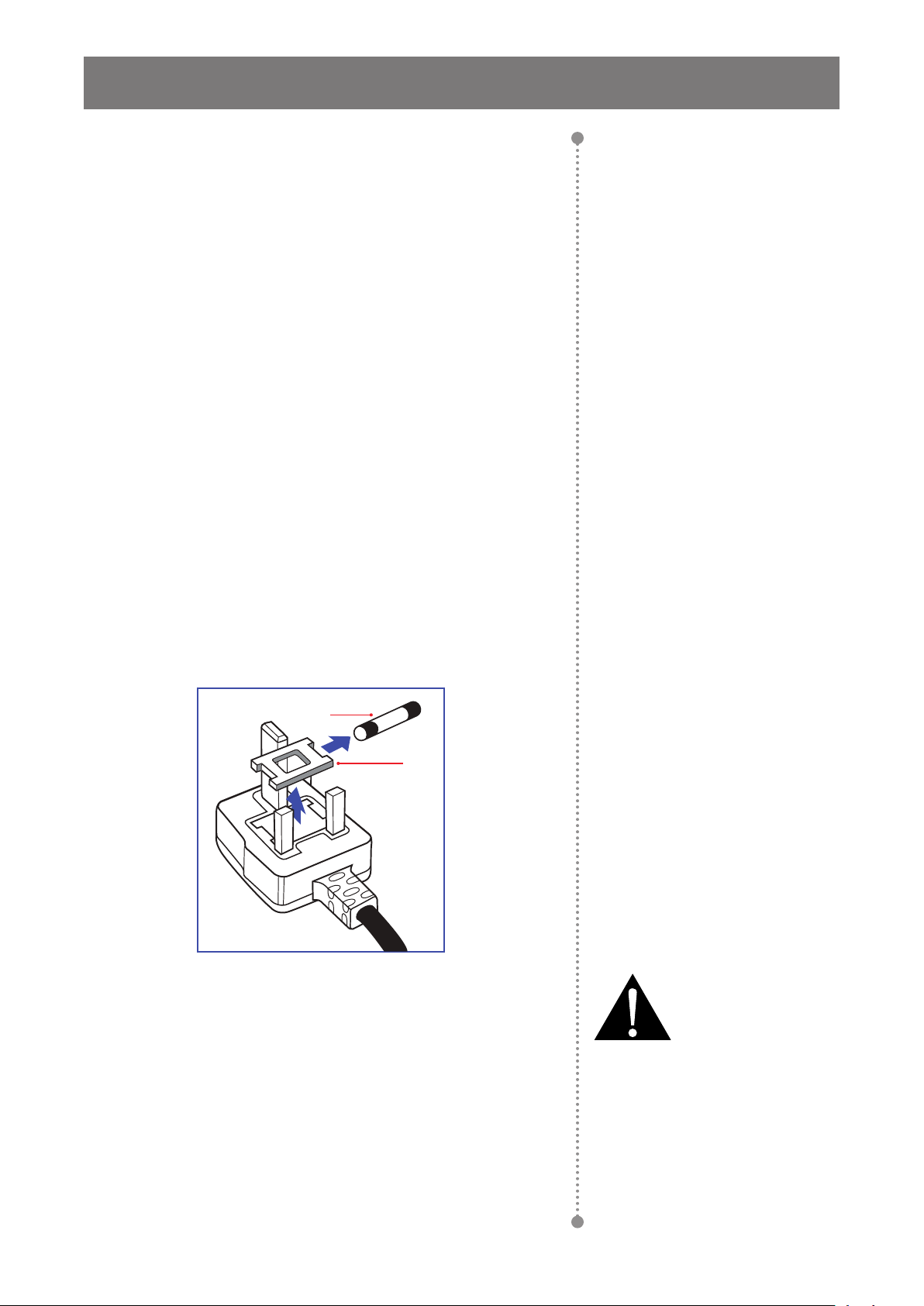
Information for U.K. only........................................................................................................................... 2
North Europe (Nordic Countries) Information........................................................................................... 4
End-of-Life Disposal ................................................................................................................................. 4
Waste Electrical and Electronie Equipment-WEEE.................................................................................. 4
Turkey RoHS............................................................................................................................................ 6
Ukraine RoHS .......................................................................................................................................... 6
PRECAUTIONS ............................................................................................ 7
Cautions When Setting Up ....................................................................................................................... 7
Cautions When Using............................................................................................................................... 8
Cleaning and Maintenance....................................................................................................................... 8
Notice for the LCD Display ....................................................................................................................... 9
CHAPTER 1: PRODUCT DESCRIPTION..................................................... 10
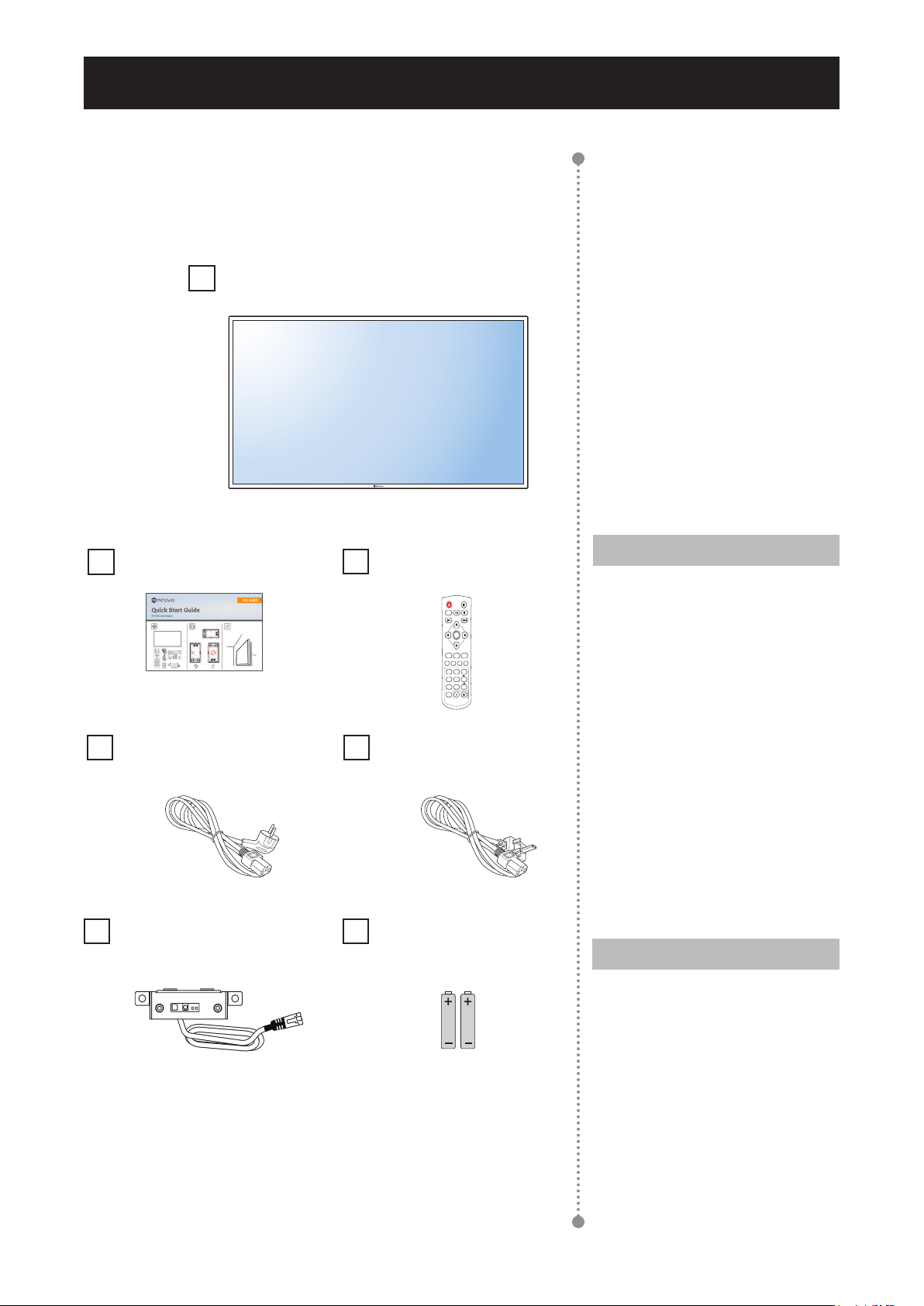
1.1 Package Contents .............................................................................................................................. 10
1.2 Moving the Display ............................................................................................................................. 11
1.2.1 Unpacking the Display............................................................................................................. 11
1.2.2 Carrying the Display ................................................................................................................ 11
1.2.3 Setting Down the Display ........................................................................................................ 11
1.3 Wall Mounting Installation................................................................................................................... 12
1.3.1 VESA Grid ............................................................................................................................... 12
1.3.2 Ventilation Requirements for Enclosure Locating.................................................................... 12
1.4 Mounting in Portrait Position .............................................................................................................. 13
1.5 LCD Display Overview ....................................................................................................................... 14
1.5.1 Input/Output Terminals ............................................................................................................ 14
1.5.2 IR and Ambient Light Sensor Ass’y ......................................................................................... 15
1.6 Remote Control .................................................................................................................................. 16
1.6.1 General Functions ................................................................................................................... 16
1.6.2 Inserting the Batteries in the Remote Control ......................................................................... 17
1.6.3 Handling the Remote Control .................................................................................................. 17
1.6.4 Operating Range of the Remote Control................................................................................. 17
CHAPTER 2: MAKING CONNECTIONS...................................................... 18
2.1 Connecting the Power ........................................................................................................................ 18
2.2 Connecting a Computer ..................................................................................................................... 19
2.2.1 Using D-SUB Input ................................................................................................................. 19
2.2.2 Using HDMI Input .................................................................................................................... 19
2.2.3 Using RS232 Input .................................................................................................................. 20
2.2.4 Using DP Input ........................................................................................................................ 20
2.3 Connecting External Equipment (Video Player)................................................................................. 21
2.4 Connecting Audio Equipment ............................................................................................................. 21

TABLE OF CONTENTS
CHAPTER 3: USING THE LCD DISPLAY.................................................... 22
3.1 Turning on the Power ......................................................................................................................... 22
3.2 Selecting the Input Source Signal ...................................................................................................... 22
3.3 Adjusting the Volume.......................................................................................................................... 23
CHAPTER 4: ON SCREEN DISPLAY MENU............................................... 24
4.1 Using the OSD Menu ......................................................................................................................... 24
4.2 OSD Menu Tree ................................................................................................................................. 25
CHAPTER 5: APPENDIX.............................................................................. 27
5.1 Warning Messages............................................................................................................................. 27
5.2 Supported Resolution......................................................................................................................... 27
5.3 Cleaning ............................................................................................................................................. 29
5.4 Troubleshooting.................................................................................................................................. 30
5.5 Transporting the LCD Display ............................................................................................................ 31
CHAPTER 6: SPECIFICATIONS .................................................................. 32
6.1 Display Specications ........................................................................................................................ 32
6.2 Display Dimensions............................................................................................................................ 33

1
SAFETY INFORMATION
CE Declaration of Conformity
This device complies with the requirements set out in the Council Directive on the Approximation of the Laws
of the Member States relating to Electromagnetic Compatibility (2014/30/EU), Low-voltage Directive (2014/35/
EU), RoHS directive (2011/65/EU).
This product has been tested and found to comply with the harmonized standards for Information Technology
Equipment, these harmonized standards published under Directives of Ofcial Journal of the European Union.
Polish Center for Testing and Certication Notice
The equipment should draw power from a socket with an attached protection circuit (a three-prong socket).
All equipment that works together (computer, display, printer, and so on) should have the same power supply
source.
The phasing conductor of the room’s electrical installation should have a reserve short-circuit protection device
in the form of a fuse with a nominal value no larger than 16 amperes (A).
To completely switch off the equipment, the power supply cable must be removed from the power supply
socket, which should be located near the equipment and easily accessible.
A protection mark “B” conrms that the equipment is in compliance with the protection usage requirements of
standards PN-93/T-42107 and PN-89/E-06251.

2
SAFETY INFORMATION
Electric, Magnetic and Electromagnetic Fields
(“EMF”)
• We manufacture and sell many products targeted at consumers,
which, like any electronic apparatus, in general have the ability to
emit and receive electromagnetic signals.
• One of our leading Business Principles is to take all necessary
health and safety measures for our products, to comply with all
applicable legal requirements and to stay well within the EMF
standards applicable at the time of producing the products.
• We are committed to develop, produce and market products that
cause no adverse health effects.
• We conrm that if its products are handled properly for their
intended use, they are safe to use according to scientic evidence
available today.
• We play an active role in the development of international
EMF and safety standards, enabling us to anticipate further
developments in standardization for early integration in its
products.
Information for U.K. Only
WARNING - THIS APPLIANCE MUST BE EARTHED.
(A)
(B)
Important:
This apparatus is supplied with an approved moulded 13A plug. To
change a fuse in this type of plug proceed as follows:
1Remove fuse cover and fuse.
2Fit new fuse which should be a BS 1362 5A,A.S.T.A. or BSI
approved type.
3Ret the fuse cover.
Note:
The severed plug must be
destroyed to avoid a possible shock
hazard should it be inserted into a
13A socket elsewhere.

3
SAFETY INFORMATION
If the tted plug is not suitable for your socket outlets, it should be cut off and an appropriate 3-pin plug tted
in its place.
If the mains plug contains a fuse, this should have a value of 5A. If a plug without a fuse is used, the fuse at
the distribution board should not be greater than 5A.
How to connect a plug
The wires in the mains lead are coloured in accordance with the following code:
BLUE - “NEUTRAL” (“N”)
BROWN - “LIVE” (“L”)
GREEN & YELLOW - “EARTH” (“E”)
• The GREEN & YELLOW wire must be connected to the terminal in the plug which is marked with the letter
“E” or by the Earth symbol or coloured GREEN or GREEN & YELLOW.
• The BLUE wire must be connected to the terminal which is marked with the letter “N” or coloured BLACK.
• The BROWN wire must be connected to the terminal which marked with the letter “L” or coloured RED.
Before replacing the plug cover, make certain that the cord grip is clamped over the sheath of the lead - not
simply over the three wires.

4
SAFETY INFORMATION
North Europe (Nordic Countries) Information
Placering/Ventilation
VARNING: FÖRSÄKRA DIG OM ATT HUVUDBRYTARE OCH UTTAG ÄR LÄTÅTKOMLIGA, NÄR DU
STÄLLER DIN UTRUSTNING PÅPLATS.
Placering/Ventilation
ADVARSEL: SØRG VED PLACERINGEN FOR, AT NETLEDNINGENS STIK OG STIKKONTAKT ER NEMT
TILGÆNGELIGE.
Paikka/Ilmankierto
VAROITUS: SIJOITA LAITE SITEN, ETTÄ VERKKOJOHTO VOIDAAN TARVITTAESSA HELPOSTI
IRROTTAA PISTORASIASTA.
Plassering/Ventilasjon
ADVARSEL: NÅR DETTE UTSTYRET PLASSERES, MÅ DU PASSE PÅ AT KONTAKTENE
FOR STØMTILFØRSEL ER LETTE Å NÅ.
End-of-Life Disposal
Your new Public Information Display contains materials that can be recycled and reused. Specialized
companies can recycle your product to increase the amount of reusable materials and to minimize the amount
to be disposed of.
Please nd out about the local regulations on how to dispose of your old display from your local dealer.
(For customers in Canada and U.S.A.)
This product may contain lead and/or mercury. Dispose of in accordance to local-state and federal regulations.
For additional information on recycling contact www.eia.org (Consumer Education Initiative).
Waste Electrical and Electronie Equipment-WEEE
Attention users in European Union private households
Disposal of Waste Equipment by Users in Private Household in the European Union.
This symbol on the product or on its packaging indicates that this product must not be disposed
of with your other household waste. Instead, it is your responsibility to dispose of your waste
equipment by handing it over to a designated collection point for the recycling of waste electrical
and electronic equipment. The separate collection and recycling of your waste equipment at the
time of disposal will help to conserve natural resources and ensure that it is recycled in a manner
that protects human health and the environment. For more information about where you can drop
off your waste equipment for recycling, please contact your local city ofce, your household waste
disposal service or the shop where you purchased the product.
For Private Households in the European Union.To help conserve natural resources and ensure the product is
recycled in a manner that protects human health and the environment, we would like to bring your attention to

5
SAFETY INFORMATION
the following:
• The crossed-out dustbin on the device or outer packaging indicates the product is compliant with European
WEEE (Waste Electrical and Electronic Equipment) Directive
• Always dispose of the old devices separately from household waste
• Batteries should be removed beforehand and disposed separately to the right collection system
• You are responsible with regard to the deletion of personal data on old devices before disposal
• Private households can hand in their old devices free of charge
• For more information about where you can drop off your waste equipment for recycling, please contact your
local city ofce, your household waste disposal service or the shop where you purchased the product
Attention users in United States:
Please dispose of according to all Local, State and Federal Laws. For the disposal or recycling information,
contact: www.mygreenelectronics.com or www.eiae.org.
End of Life Directives-Recycling
Your new Public Information Display contains several materials that can be recycled for new
users.
Please dispose of according to all Local, State, and Federal laws.
Restriction on Hazardous Substances statement (India)
This product complies with the “India E-waste Rule 2011” and prohibits use of lead, mercury, hexavalent
chromium, polybrominated biphenyls or polybrominated diphenyl ethers in concentrations exceeding 0.1
weight % and 0.01 weight % for cadmium, except for the exemptions set in Schedule 2 of the Rule.
E-Waste Declaration for India
This symbol on the product or on its packaging indicates that this product must not be disposed
of with your other household waste. Instead it is your responsibility to dispose of your waste
equipment by handing it over to a designated collection point for the recycling of waste electrical
and electronic equipment . The separate collection and recycling of your waste equipment at
the time of disposal will help to conserve natural resources and ensure that it is recycled in a
manner that protects human health and the environment.
Batteries
For EU: The crossed-out wheeled bin implies that used batteries should not be put to the
general household waste! There is a separate collection system for used batteries, to allow
proper treatment and recycling in accordance with legislation.
Please contact your local authority for details on the collection and recycling schemes.
For Switzerland: The used battery is to be returned to the selling point.
For other non-EU countries: Please contact your local authority for correct method of
disposal of the used battery.

6
SAFETY INFORMATION
According to EU directive 2006/66/EC, the battery can’t be disposed improperly. The battery shall be
separated to collect by local service.
Turkey RoHS
Türkiye Cumhuriyeti: EEE Yönetmeliğine Uygundur.
Ukraine RoHS
Обладнання відповідає вимогам Технічного регламенту щодо обмеження використання деяких
небезпечних речовин в електричному та електронному обладнанні, затвердженого постановою Кабінету
Міністрів України від 3 грудня 2008 № 1057.

7
CAUTION
RISK OF ELECTRIC SHOCK
DO NOT OPEN
Symbols used in this manual
This icon indicates the existence of a potential hazard that could result in personal injury
or damage to the product.
This icon indicates important operating and servicing information.
Notice
• Read this User Manual carefully before using the LCD display and keep it for future reference.
• The product specications and other information provided in this User Manual are for reference only. All
information is subject to change without notice. Updated content can be downloaded from our web site at
www.agneovo.com.
• To protect your rights as a consumer, do not remove any stickers from the LCD display. Doing so may
affect the determination of the warranty period.
Cautions When Setting Up
• Do not place the LCD display near heat sources, such as a heater, exhaust vent, or in direct sunlight.
• Do not cover or block the ventilation holes in the housing.
• Place the LCD display on a stable area. Do not place the LCD display where it may subject to vibration or
shock.
• Place the LCD display in a well-ventilated area.
• Do not place the LCD display outdoors.
• To avoid the risk of shock or permanent damage to the set, do not expose the display to dust, rain, water or
an excessively moist environment.
• Do not spill liquid or insert sharp objects into the LCD display through the ventilation holes. Doing so may
cause accidental re, electric shock or damage the LCD display.
PRECAUTIONS

8
PRECAUTIONS
Warning:
Unplug the power cord
from the power outlet and
refer to qualied service
personnel under the following
conditions:
♦When the power cord is
damaged.
♦If the LCD display has been
dropped or the housing has
been damaged.
♦If the LCD display emits smoke
or a distinct odor.
Cautions When Using
• Use only the power cord supplied with the LCD display.
• The power outlet should be installed near the LCD display and
be easily accessible.
• If an extension cord is used with the LCD display, ensure that the
total current consumption plugged into the power outlet does not
exceed the ampere rating.
• Do not allow anything to rest on the power cord. Do not place the
LCD display where the power cord may be stepped on.
• If the LCD display will not be used for an indenite period of time,
unplug the power cord from the power outlet.
• To disconnect the power cord, grasp and pull by the plug head.
Do not tug on the cord; doing so may cause re or electric shock.
• Do not unplug or touch the power cord with wet hands.
• When turning off the display by detaching the power cord, wait 6
seconds before re-attaching the power cord for normal operation.
• Do not knock or drop the display during operation or
transportation.
Cleaning and Maintenance
• To protect your display from possible damage, do not put
excessive pressure on the LCD panel. When moving your
display, grasp the frame to lift; do not lift the display by placing
your hand or ngers on the LCD panel.
• Unplug the display if you need to clean it with a slightly damp
cloth. The screen may be wiped with a dry cloth when the power
is off. However, never use organic solvent, such as, alcohol, or
ammonia-based liquids to clean your display.
• If your display becomes wet, wipe it with dry cloth as soon as
possible.
• If a foreign substance or water gets in your display, turn the
power off immediately and disconnect the power cord. Then
remove the foreign substance or water, and send the unit to the
maintenance center.
• In order to maintain the best performance of your display and
ensure a longer lifetime, we strongly recommend using the
display in a location that falls within the following temperature
and humidity ranges.
♦Temperature: 0-40°C (32-104°F)
♦Humidity: 20-80% RH

9
PRECAUTIONS
Notice for the LCD Display
• In order to maintain the stable luminous performance, it is recommended to use low brightness setting.
• Due to the lifespan of the lamp, it is normal that the brightness quality of the LCD display may decrease
with time.
• When static images are displayed for long periods of time, the image may cause an imprint on the LCD
display. This is called image retention or burn-in.
♦To prevent image retention, do any of the following:
• Set the LCD display to turn off after a few minutes of being idle.
• Use a screen saver that has moving graphics or a blank white image.
• Execute the Anti-Burn-in function of the LCD display. See “Anti-Burn-in” on page 25.
• Switch desktop backgrounds regularly.
• Adjust the LCD display to low brightness settings.
• Turn off the LCD display when the system is not in use.
♦Things to do when the LCD display shows image retention:
• Turn off the LCD display for extended periods of time. It can be several hours or several days.
• Use a screen saver and run it for extended periods of time.
• Use a black and white image and run it for extended periods of time.
• There are millions of micro transistors inside the LCD display. It is normal for a few transistors to be
damaged and to produce spots. This is acceptable and is not considered a failure.
• IMPORTANT: Always activate a moving screen saver program when you leave your display unattended.
Always activate a periodic screen refresh application if the unit will display unchanging static content.
Uninterrupted display of still or static images over an extended period may cause “burn in”, also known
as “after-imaging” or “ghost imaging”, on your screen. This is a well-known phenomenon in LCD panel
technology. In most cases, the “burned in” or “after-imaging” or “ghost imaging” will disappear gradually
over a period of time after the power has been switched off.
• WARNING: Severe “burn-in” or “after-image” or “ghost image” symptoms will not disappear and cannot be
repaired. This is also not covered under the terms of your warranty.

10
1.1 Package Contents
When unpacking, check if the following items are included in
the package. If any of them is missing or damaged, contact your
dealer.
Quick Start Guide
Power Cord (for EU
except UK)
Note:
♦The pictures are for reference
only. Actual items may vary
upon shipment.
POWER
F1 F2 F3 F4
MUSIC
2
MOVIE
3
PHOTO
1
ROTATE
5
16:9/4:3
4
ENTER
MENU
MUTE
SLIDE SHOW SOURCEEXIT
6
OSD
8
ZOOM
7 9
BACKMUSIC
0
VOL
AAA
AAA
Remote Control
Battery AAA x2
LCD Display
Note:
♦Remote control is shipped with
the supplied AAA batteries.
♦For all other regions, apply a
power cord that conforms to
the AC voltage of the power
socket and has been approved
by and complies with the safety
regulations of the particular
country.
♦You might like to save the
package box and packing
material for shipping the
display.
CHAPTER 1: PRODUCT DESCRIPTION
Power Cord (for UK)
IR and Ambient Light
Sensor Ass’y

11
PRODUCT DESCRIPTION
1.2 Moving the Display
1.2.1 Carrying the Display
When carrying the display, always hold it with two people using both
hands and the screen facing forward.
1.2.2 Setting Down the Display
When setting the display down, place the screen face down on a at
and stable surface covered by a protective sheet and a table cushion
as shown in the illustration provided.
1.2.3 Placing the Display
When placing the display, keep the display upright. Never tilt the
display towards the left, right, or balanced on a single corner of the
frame.
Warning:
♦Do not press too hard on the
LCD panel or edge of the
frame, as this may cause the
device to malfunction.
♦During unpacking, make sure
to hold the carrying handles
to remove the device from its
packaging.
Caution:
♦Avoid applying force or using
sharp objects on the LCD panel
at all times.
Caution:
♦Never press or place anything
on the back cover. This may
damage the internal parts of the
display.

12
PRODUCT DESCRIPTION
1.3 Wall Mounting Installation
To mount this display to a wall, you will have to obtain a standard wall-
mounting kit (commercially available).
To wall-mount the LCD display, screw the mounting bracket to the
VESA holes at the rear of the LCD display.
600mm
400mm
1.3.1 VESA Grid
Model Name VESA Grid
PO-5502 600(H) x 400(V) mm
Caution:
To prevent the display from falling:
♦For wall or ceiling installation, we recommend installing the display
with metal brackets which are commercially available.
♦AG Neovo also provides a great variety of wall mounts for different
installation uses. For more information, please visit: www.agneovo.
com/accessories
♦To lessen the probability of injury and damage resulting from fall of
the display in case of earthquake or other natural disaster, be sure
to consult the bracket manufacturer for installation location.
1.3.2 Ventilation Requirements for Enclosure Locating
To allow heat to disperse, leave space between surrounding objects as
shown in the diagram below.
Note:
♦Avoid the wall-mounting kit to
block the ventilation holes on the
back of the display.
♦Make sure the distance between
the LCD display fans and the
wall is at least 4~5 cm.
♦Secure the LCD display (Unit
weight= 23.5 kg/ 51.8lbs.) on a
solid wall strong enough to bear
its weight.
♦Lay a protective sheet on a table,
which was wrapped around the
display when it was packaged,
beneath the screen surface so as
not to scratch the screen face.
♦For the wall-mounting kit, use
M6 mounting screws (having
a length 18 mm longer than
the thickness of the mounting
bracket) and tighten them
securely.

13
PRODUCT DESCRIPTION
40 mm 40 mm
40 mm
40 mm
1.4 Mounting in Portrait Position
This display can be installed in portrait position.
Rotate 90 degrees counter-clockwise such that one of the arrows on the rear of the LCD display is pointing up
and the other to the left side (as illustrated below).
90 90

14
PRODUCT DESCRIPTION
1.5 LCD Display Overview
1.5.1 Input/Output Terminals
DP
IR
RS232 OUTRS232 INHDMI 2HDMI 1D-SUBAudio
IN
Audio
OUT
10 111 2 3 4 65 7 8 9
1AUDIO OUT
Connects with external speakers or
audio amplier to output the audio that
is supplied by th vedio source.
2AUDIO IN
Connects with the audio out connector
of a video source such as a computer,
video player when the display is
connected to the source via the D-SUB.
3D-SUB
Connects with the analog video output
(VGA) of a computer.
5HDMI 1/ HDMI 2
Connects with devices supporting
audio/video data using the HDMI
interface.
6IR
It can only connect with the accessory “IR
and ambient light sensor ass’y.”
7RS232 IN
Connect RS232 input from external
equipment.
8RS232 OUT
Connect RS232 output to additional
displays.
9DisplayPort (DP)
Connects with devices transmitting audio/
video using the Display Port interface.
10 AC-IN
Connects with the supplied power cord
11 Main Power switch
Switches the main power on or off.
4

15
PRODUCT DESCRIPTION
1.5.2 IR and Ambient Light Sensor Ass’y
IR
123
1IR Sensor Indicator
Displays the status of the IR sensor.
• Green: The display’s power is on.
• Red: The display is in power saving
mode.
• Off: The display’s power is off.
2IR Sensor
The IR sensor board needs to be
connected to the IR hole rst.
Receives the signal from the remote
control.
3Light Sensor
Receives ambient light and enable
automatic backlight adjustment.
Note:
♦Please make sure the light sensor
is not covered when enabling Auto
Dimming function.
♦The IR and ambient light sensor
ass’y can be magnetised and
easily moved to the rear of the
displays or the iron cases to suit
different outdoor environments.

16
PRODUCT DESCRIPTION
1.6 Remote Control
1.6.1 General Functions
POWER
F1 F2 F3 F4
MUSIC
2
MOVIE
3
PHOTO
1
ROTATE
5
16:9/4:3
4
ENTER
MENU
MUTE
SLIDE SHOW SOURCEEXIT
6
OSD
8
ZOOM
7 9
BACKMUSIC
0
VOL
6
7
2
8
1
3
5
4
1
[ ]POWER
Turns the display on or off.
Note:
♦If the power indicator is not lit then the
controls will not function.
2[ ] MUTE
Press the MUTE button to mute the audio.
3MENU
Displays the OSD menu. Please refer to page 24.
4[ ] [ ] [ ] [ ] NAVIGATION buttons
Navigates through menus, selects items, and
adjusts values.
5EXIT
Exits the current menu.
6ENTER
Selects items or accepts the settings made in the
OSD menu.
7SOURCE
Switches the video input source. Use the [] [
]buttons to select [D-SUB], [HDMI1], [HDMI2], or
[DP] and press the ENTER button to confirm the
selection.
8[ ] [ ] VOL
• Press [ ] to decrease volume.
• Press [ ] to increase volume.
Note:
♦The unlabeled buttons do not support functions.

17
PRODUCT DESCRIPTION
1.6.2 Inserting the Batteries in the Remote Control
The remote control is powered by two 1.5V AAA batteries.
To install or replace batteries:
1Open the remote control battery compartment cover.
2Align the batteries according to the (+) and (-) indications
inside the battery compartment.
3Replace the cover.
1.6.3 Handling the Remote Control
• Do not subject to strong shock.
• Do not allow water or other liquid to splash the remote control. If
the remote control gets wet, wipe it dry immediately.
• Avoid exposure to heat and steam.
• Other than to install the batteries, do not open the remote
control.
1.6.4 Operating Range of the Remote Control
Point the top of the remote control toward the display’s remote
control sensor when pressing a button.
Point the remote control toward the display’s IR sensor within a
distance of less than 3 m / 9.84 ft, and a horizontal and vertical
angle of less than 30 degrees, when operating the remote control.
30°30°
Caution:
The incorrect use of batteries can
result in leaks or bursting. Be sure
to follow these instructions:
♦Place “AAA” batteries
matching the (+) and (–) signs
on each battery to the (+)
and (–) signs of the battery
compartment.
♦Do not mix battery types.
♦Do not combine new batteries
with used ones. It causes
shorter life or leakage of
batteries.
♦Remove the dead batteries
immediately to prevent them
from liquid leaking in the
battery compartment. Don’t
touch exposed battery acid, as
it can damage your skin.
Note:
♦If you do not intend to use
the remote control for a long
period, remove the batteries.
♦The remote control may not
function properly when the
remote control sensor on this
display is under direct sunlight
or strong illumination, or when
there is an obstacle in the path
of signal transmission.
Table of contents
Other AG Neovo Monitor manuals

AG Neovo
AG Neovo F-417 User manual

AG Neovo
AG Neovo F-317A User manual

AG Neovo
AG Neovo PS-46 User manual

AG Neovo
AG Neovo L-W27 User manual

AG Neovo
AG Neovo HX-Series User manual

AG Neovo
AG Neovo TS-17R User manual

AG Neovo
AG Neovo S-18 User manual

AG Neovo
AG Neovo SeriesPLUS Display F-315 User manual

AG Neovo
AG Neovo X-20 User manual

AG Neovo
AG Neovo P-17 User manual

AG Neovo
AG Neovo RX-W22 User manual

AG Neovo
AG Neovo S-15E User manual

AG Neovo
AG Neovo S-15V User manual

AG Neovo
AG Neovo F-17C User manual

AG Neovo
AG Neovo DR-17 User manual

AG Neovo
AG Neovo C-19P User manual

AG Neovo
AG Neovo F-15 User manual

AG Neovo
AG Neovo EM989 User manual

AG Neovo
AG Neovo E-W22 User manual

AG Neovo
AG Neovo E-19A User manual