AG Neovo X-20A User manual

X-20A LCD Monitor
Service Menu

1
Table of Contents
Chapter One:Precautions--------------------------------------------------------------------------2
Chapter Two:Package Contents-----------------------------------------------------------------3
Chapter Three:Identifying Parts and Controls------------------------------------------------4
Chapter Four:Setup---------------------------------------------------------------------------------6
Chapter Five:Customizing Your Monitor-------------------------------------------------------8
1. Introducing the On-Screen Display System----------------------------8
2. The On-Screen Display Function Tree-----------------------------------8
3. The On-Screen Display Function Description--------------------------9
Chapter Six:Warning Messages and Trouble Shooting-----------------------------------11
Chapter Seven:Technical Features and Specifications-----------------------------------13
Chapter Eight:Mechanical Diagram------------------------------------------------------------15
Chapter Nine:Circuit Diagram-------------------------------------------------------------------16

2
Chapter One:Precautions
Warning on installation
• Do not cover or block the ventilation holes in the case.
• Do not install the monitor near heat sources such as radiators or air ducts, or in a place subject
to direct sunlight, excessive dust, mechanical vibration or shock.
Warning on power connection
• Use an appropriate power cord for your local power supply.
• The outlet should be installed near the monitor and be easily accessible.
• Do not allow anything to rest on the power cord.
• Disconnect the power plug from the power outlet under following conditions:
i. If you will not use it for an indefinite period time.
ii. When the power cord or plug is damaged of frayed.
iii. If the product has been dropped or the cabinet has been damaged.
iv. If the product exhibits a distinct change in performance, indicate a need for service.
Warning on tilt
• With the tilt, this monitor can be adjusted to the desired angle within 0º ~ 15º degree vertically.
To turn the monitor vertically, hold it at the top with both hands as illustrated below.
Warning on Maintenance
• Clean the cabinet, glass, and controls with a soft cloth lightly moistened with a mild detergent
solution. Do not use any type of abrasive pad, scouring powder or solvent, such as alcohol or
benzene.
• Do not rub, touch, or tap the surface of the screen with sharp or abrasive items such as a pen or
screwdriver. This type of contact may result in a scratched glass.
• Do not insert sharp objects or spill liquid into the monitor through ventilation holes. They may
cause accident fire, electric shock or failure.
• Do not attempt to service this product yourself, as opening or removing covers may expose you
to dangerous voltage potentials or other risks.
Warning on transportation
• When you transport this monitor for repair or shipment, use the original carton and packing
materials.

3
Chapter Two:Package Contents
Before using this monitor, check the following items are included in your carton box:
LCD monitor 20.1-inch monitor
Remote control
Power cord
D-sub 15-pin VGA
cable
Video cable
(Mini-DIN, 6 pin to
component)
—(Optional)
Audio line-in/line-out
cable
CVBS cable
(Optional)
S-Video cable
(Optional)
Floppy/CD-ROM
(containing Windows
information file and
this user’s manual)
Quick Setup Guide
Chapter Three:Identify the Parts and Controls

4
PIP
INPUT
AUTO
POWER
Side view
Menu button
Opens the OSD Menu
Mute button
Toggles audio mute on/off
UP/PIP button
Scrolls through PIP options and navigates within the OSD
DOWN/INPUT button
Toggles through Input options and navigates within the OSD
+ INCREASE/Volume/ button, activate sub menu
Increases the volume and navigates within the OSD
— DECREASE button
Decreases the volume (you must push the INCREASE button before you can use the DECREASE button) and navigates
within the OSD
AUTO button
Automatically adjusts the picture and performance. The AUTO function should be used the first time you use the monitor
and after changing the resolution and/or refresh rate of the input signal.
Power Switch/LED indicator
Turns the monitor on and off
Indicates the monitor’s operational mode; green for regular operation, and amber for power saving mode.
DC +12V Power inlet
• Provides +12V DC power to the monitor
ANALOG
• D-sub 15-pin connector for analog signal input
Rear View

5
DIGITAL
• DVI-D connector for digital signal input
S-VIDEO
• S-Video connector for S-video signal input
VIDEO
• RCA connector for CVBS video signal input
Chapter Four:Setup
Please follow the steps one by one to setup your monitor.
1 Split the dust-proof plastic sheet
Split the dust-proof plastic sheet from the screen surface of monitor.
2 Connect the monitor to the computer (if you are using a video source, please skip this step.)
There are two kinds of signal formats that are digital and analog. This monitor can support both of
them. Depending on the output signal of your computer, you may need to use different signal cable
and to connect into different port of the monitor.
2.1 Connecting to an IBM PC/AT or compatible computer by using the D-Sub 15-pin
cableWith the computer being switched off, connect the analog VGA signal cable to the
“ANALOG” port at rear of the monitor and computer.
2.2 Connecting to an IBM PC/AT or compatible computer by using the DVI cableWith the
computer being switched off, connect the digital DVI signal cable to the “DIGITAL” port at
rear of the monitor and computer.
2.3 Connecting to a Macintosh or compatible computer
With the computer being switched off, connect the analog VGA signal cable to the
“ANALOG” port at rear of the monitor and computer.
3 Connect the monitor to the video source (DVD, VCD, VCR, etc.) (If you are using a computer,
please skip this step.)
This monitor can support both S-Video and RCA jack. Depending on the signal output port of your
video source, you may need to use different signal cable and to connect into different port of the
monitor. (If both the ports are available in your video source, the S-Video connection is
recommended for better performance.)
3.1 Connecting to a video source with the S-Video cable
With the video source being switched off, connect the S-Video cable to the “S-VIDEO”
port at rear of the monitor and video source.
3.2 Connecting to a video source with the RCA cable
With the video source being switched off, connect the RCA cable to the “VIDEO” port at
rear of the monitor and video source.
4 Connect the power adapter and power cord
4.1 With the monitor switched off, connect the cable of power adapter to

6
the monitor.
5 Turn on the monitor and computer
5.1 Turn on your computer.
5.2 Press the (Power) switch to turn on your monitor. You should see the picture on your
monitor now. If not, please check the “Warning Signal and Trouble Shooting” section of
this user manual for details.
6 Use 1280x1024 resolution and press (AUTO) button for best performance. (If you are not using
a computer, please skip this step.)
6.1 Before starting to work, you are recommended to adjust the resolution of video signal
from your computer to 1600x1200 at 60Hz for best picture performance. (Please check
the user manual of your computer to learn how to adjust the resolution and refresh rate.)
6.2 You are also recommended to press the (AUTO) button to adjust the picture
performance automatically and to ensure the tolerance-free picture.
7 Install information file for Microsoft Windows 95/98
7.1 The information file (also known as driver) for Microsoft Windows 95/98 are available in
the attached floppy disk or CD-ROM. You may install it for better communication
between your monitor and Windows 95/98. Please refer to the text file of “readme.txt”
in the attached floppy disk or CD-ROM for details
8 Preparing the Remote Control
The remote control lets you comfortably change settings such as volume and
input devices. The remote control is stored in the back of the monitor.
The remote control ships with a plastic contact breaker between the battery and
contact. You must remove the contact breaker before use.
9 Replacing the Remote Control Battery
If you notice the remote control does not work, try replacing the battery. Refer
to the following:
Remove the battery bay by pushing and holding in the direction of the arrow (A), and then
pulling in the direction of the arrow (B). Remove the battery

7
Insert a new battery with
the positive (+) side facing
up.
Replace the battery bay.
Chapter Five:Customizing Your Monitor
Main Picture Adjustment
Brightness & Contrast
To fine-tune the monitor’s brightness and contrast, select the item from the menu.
Use the INCREASE and DECREASE buttons to set the display as desired on the
0-100 scale that appears at the bottom of the window.
Push ENTER (remote control) to save settings and return to the Group selection menu.
Horizontal & Vertical Position
To fine-tune the display’s position on the monitor screen, select the item from the menu.
Use the INCREASE and DECREASE buttons to set the display as desired on the
0-100 scale that appears at the bottom of the window.
Push ENTER (remote control) to save settings and return to the Group selection menu.
Phase & Frequency
To fine-tune picture performance to compensate for in the computer signal, select the item
from the menu.drifts
Use the INCREASE and DECREASE buttons to set the display as desired on the
0-100 scale that appears at the bottom of the window.
Push ENTER (remote control) to save settings and return to the Group selection menu.
Main Scaling

8
There are three settings for Main Scaling:
Full Full-screen is displayed regardless of the input device.
Fixed
Aspect Full-screen display for PC input.
Video input will depend on signal. The standard 4:3 screen will appear
as full screen; however, the wide screen 16:9 format appears with a
black border at top and bottom of screen.
1:1 If the resolution of the input device is lower than the monitor, a
smaller screen is displayed.
To adjust the scaling, select the item from the menu.
Use the INCREASE and DECREASE buttons to scroll through the settings: FULL;
FIXED ASPECT; 1 1.
Push ENTER (remote control) to save settings and return to the Group selection menu.

9
Sub Picture Setting
The SUB Picture or PIP (Picture In Picture) allows you to view a small video
window in the middle of your full-screen display. Depending on your input
source, this feature can be used for watching TV while using your computer. It
can also be used in videoconferencing to see how you appear to the other
members in the conference.
Before you can make changes to the PIP video quality screen, you must enable
the PIP feature and choose the source. The following screens allow you to
change settings for SUB Picture. Main Picture and Sub Picture will depend on
the input source. Refer to Main Picture Settings on page 錯誤! 尚未定義書籤。
for all possible settings.
Color Setting
Auto White Balance
Use this setting to ensure the analog to digital converter gain is synchronized.
Selecting a Color Temperature setting
The following conditions are recommended for the available settings:
Setting Use
9300K General Use
6500K Color Management
5500K Photo Retouching
Select the desired setting from the menu.
Use the INCREASE and DECREASE buttons to enable the item.
Push ENTER (remote control) to save settings and return to the Group selection menu.

10
Selecting a User-Defined Color Balance Setting
You can fine-tune the red/green/blue picture settings according to your
preference or specific application.
Select the color category from the menu.
Use the INCREASE and DECREASE buttons to set each color as desired on the
0-100 scale.
Use the DOWN or UP buttons to select the next color.
Push ENTER (remote control) twice to save settings and return to the Group selection menu.
PIP Settings
To enjoy your monitor’s PIP feature, you should first connect your input source
to the rear of the monitor (see Making Connections on page 錯誤! 尚未定義書
籤。). In the following screen, first enable PIP and then select the input source
that is connected to the monitor.
Type Three PIP settings (Windows Type) are available:
Windows Type Description
Off PIP is disabled.
Picture in Picture A smaller (resizable) sub screen is shown
inside the main screen.
Picture by Picture The sub screen and main screen are the
same size and shown side by side.
Push the UP button on the side of the monitor.
Windows Type
Picture in Picture
Push the UP button to move through the options and select the option you want.
Sub Source
When two video sources are connected to the monitor, use this setting to
choose which is the sub (PIP) source.
To select the Sub source, select the item from the menu.
Use the INCREASE and DECREASE buttons to choose a new Sub source.
Sub Size
To resize the PIP window, select the item from the menu.
Use the INCREASE and DECREASE buttons to set as desired on the 50/100 scale.

11
Push ENTER (remote control) to save settings and return to the Group selection menu.
H-Position & V-Position
To change the horizontal and vertical position of the PIP window on the monitor screen,
select the item from the menu.
Use the INCREASE and DECREASE buttons to set the display as desired on the
0-100 scale.
Push ENTER (remote control) to save settings and return to the Group selection menu.
Transperency
To change the transparency of the PIP window, select the item from the menu.
Use the INCREASE and DECREASE buttons to set as desired on the 0-16 scale: 0
= transparent; 16 = solid.
Push ENTER (remote control) to save settings and return to the Group selection menu.
Misc Setting
Sharpness
To set the sharpness of the display, select Sharpness from the menu.
Use the INCREASE and DECREASE buttons to set the sharpness as desired on the
1-100 scale.
Push ENTER (remote control) to save settings and return to the Group selection menu.
Backlight
To set the brightness of the monitor’s backlight, select Backlight from the menu.
Use the INCREASE and DECREASE buttons to set the brightness as desired on
the 1-100 scale.
Push ENTER (remote control) to save settings and return to the Group selection menu.
DOS This item is only available in DOS mode.
Recall
To return the monitor’s settings to the factory default, select Recall from the menu.
Use the INCREASE and DECREASE buttons to reset the monitor to its factory
default settings.
Sub Info This item displays the Sub input source and internal settings version of the
monitor.

12
OSD Setting
H/V Position
To position the OSD window to your preference, select the item from the menu.
Use the INCREASE and DECREASE buttons to change the horizontal/vertical
position of the OSD.
Push ENTER (remote control) to save settings and return to the Group selection menu.
Timeout
To set the duration of the OSD window’s display, select the item from the menu.
Use the INCREASE and DECREASE buttons to set the time from 5 to 60 seconds
in increments of five seconds.
Push ENTER (remote control) to save settings and return to the Group selection menu.
Language
To select the language for the OSD interface, select the item from the menu.
Use the INCREASE and DECREASE buttons to scroll through the available
languages.
Push ENTER to save settings and return to the Group selection menu.
Size
To change the size of the OSD window, select the item from the menu.
Use the INCREASE and DECREASE buttons to scroll through the options: 0 =
small; 1 = medium; 2 = large.
Push ENTER to save settings and return to the Group selection menu.
Transparency
To change the transparency of the OSD, select the item from the menu.
Use the INCREASE and DECREASE buttons to set as desired on the 0-16 scale: 0
= transparent; 6 = solid.
Push ENTER to save settings and return to the Group selection menu.
Audio Setting
Note! To avail of the monitor’s built-in audio features you must connect speakers to
the monitor.

13
Volume Adjust
To adjust the monitor’s volume output, select the item from the menu.
Use the INCREASE and DECREASE buttons to set the volume as desired on the
0-100 scale.
Push ENTER to save settings and return to the Group selection menu.
Mode The following settings allow you to enhance your monitor’s audio features.
Bypass
Use this setting to disable the monitor’s special SRS®audio effects.
SRS 3D™ SRS (Sound Retrieval System) 3D™is the leading 3D sound technology in the world. SRS is based on
the human hearing system and was designed to retrieve the natural spatial cues and ambient information
that is present in audio but masked by traditional recording and playback methods. SRS has no sweet
spot and fills the room with a sound experience much closer to that of a live performance.
WOW™ WOW™ is a special combination of SRS audio technologies that creates a thrilling surrounding sound
experience with deep rich bass from mono or stereo sound sources. The audio sounds fuller, richer, and
wider. Based on the elements of the flagship SRS 3D technology, WOW restores the spatial cues and
ambient information that are lost during standard stereo playback.
To enable, select the item from the menu.
Use the INCREASE and DECREASE buttons to enable the item.
Volume/Mute Adjust
Use the INCREASE and DECREASE buttons to quickly adjust the
volume of the monitor’s built-in stereo speakers.
Volume
Push the INCREASE button to open the Volume adjust window.
Use INCREASE and DECREASE buttons to set the volume as desired.
Push ENTER to save settings and close the Volume adjust window.

14
Chapter Six:Warning Messages and Trouble Shooting
Warning Messages
Message Solution
CAN NOT DISPLAY THIS
INPUT SIGNAL
The input signal is not acceptable by the monitor.
• Ensure that the video resolution and frequency range are within that specified for
the monitor. (Refer to the “Technical Specifications” section of this user’s manual
for details.)
NO SIGNAL INPUT No signal inputs are detected from either VGA-In or S-Video connectors.
• Check that the power switch of your computer or video source is in the “ON”
position.
• Check that the video signal cable is properly connected.
• Ensure that no pins are bent or pushed in the video-input connector.
MAIN CONTROL MENU
LOCKED/UNLOCKED
The main control menu (On-Screen Display menu) is locked to avoid unwanted
adjustment.
• Press and hold the INCREASE , DECREASE and POWER buttons
together for five seconds to lock/unlock the main control menu.
ADJUSTING FREQUENCY
ADJUSTING PHASE
ADJUSTING POSITION
The monitor is detecting the input signal and automatically adjusting the monitor
parameters accordingly.
It takes around 5 seconds to finish the whole process.
• You are recommended to auto adjust by pressing the button every time you
change the resolution or refresh rate.
Trouble Shooting
Symptom Check Items
• No picture
• LED power indicator is not lit
• Check that the monitor power switch is turned on.
• Check that the power cord is properly connected to the power outlet and the
monitor.
• Check if there is electrical power coming from the power outlet. Use another
device to check for power.
• No picture
• The LED power indicator is
orange
• Ensure the computer is not in power saving mode. (Move the mouse or press a
key on the keyboard to wake up the computer.)
• Check that your computer is in the “ON” position.
Text is not solid • Ensure that the resolution of the video signal is 1600 by 1200.
• Press the button to run automatic adjustment.
• Adjust Clock and Phase in the OSD menu to fine-tune. (Refer to the
“Customizing Your Monitor” section of this user’s manual for details.)
• Adjust Sharpness in the OSD menu if you are not in 1600 by 1200 resolution.
(Please refer to the “Customizing Your Monitor” section of this user’s manual
for details.)
• Screen image is not centered
properly
• Press the button to run automatic adjustment.
• Adjust H. Position and V. Position to fine-tune. (Refer to the “Customizing

15
• Some lines are missing Your Monitor” section of this user’s manual for details.)
There are tiny red, green, blue or
black dots on the screen.
The TFT LCD panel consists of millions of small transistors. Defective transistors
will each cause a missing red, green, or blue dot.
Chapter Seven:Technical Features and Specifications
1 Power Saving Function
This monitor meets the power-saving guidelines set by VESAand Energy Star, as well as the more
stringent NUTEK.
If the monitor is connected to a computer that is VESADPMS (Display Power Management
Signaling) compliant, the monitor will automatically reduce power consumption in the three stages
as shown below.
Mode Screen Power
Consumption LED indicator
Normal Active < 40 W Green
Standby Blank < 5 W Orange
Suspend Blank < 5W Orange
Active-off Blank < 5 W Red
2 Plug & Play
This monitor complies with the DDC1 and DDC2B Display Data Channel (DDC) Standards of
VESA.
3 Preset and User Modes
This monitor has factory preset modes for the 20 most popular industrial standards. Another 20
user modes are also available to store user adjustments.
N0. Resolution Horizontal
Frequency Vertical
Frequency Mode
1 640x350 31.5KHz 70Hz IBM VGA
2 640x480 31.5KHz 60Hz IBM VGA
3 640x480 35.0KHz 67Hz Macintosh
4 640x480 37.9KHz 72Hz VGA/72
5 640x480 37.5KHz 75Hz VGA/75
6 720x400 31.5KHz 70Hz IBM VGA
7 800x600 35.2KHz 56Hz SVGA/56
8 800x600 37.9KHz 60Hz SVGA/60
9 800x600 48.1KHz 72Hz SVGA/72
10 800x600 46.9KHz 75Hz SVGA/75
11 832x624 49.7KHz 75Hz Macintosh
12 1024x768 48.4KHz 60Hz XGA/60
13 1024x768 56.5KHz 70Hz XGA/70
14 1024x768 60.0KHz 75Hz XGA/75
15 1152x864 63.9KHz 70Hz VESA
16 1152x864 67.5KHz 75Hz VESA

16
17 1152x870 68.7KHz 75Hz VESA
18 1280x960 60.0KHz 60Hz VESA
19 1280x1024 64.0KHz 60Hz SXGA/60
20 1280x1024 80.0KHz 75Hz SXGA/75
21 1600x1200 75.0KHz 60Hz UXGA/60
22 1600x1200 93.0KHz 75Hz UXGA/75
4 Specifications
Electrical characteristics
20” (51cm) diagonal
408 x 306 mm
0.27mm x 0.27mm
1600 x 1200 vertical stripe
30kHz –90kHz
30Hz – 80Hz
VGA Analog Max:203MHz
VGA DVI Max:165 MHz
24-bit interface (16M colors)
600:1 (typical)
250 cd/m2 (typical)
160/160 degree (minimum)
Screen size
Active area
Pixel pitch
Pixel format
Horizontal frequency
Vertical frequency
Maximum pixel clock
Color depth
Contrast ratio
Brightness
Viewing angle (CR >
10)
Connections Power: +12 Volts DC input
ANALOG: Mini D-Sub 15-pin connector
DIGITAL: DVI-D connector
S-VIDEO: S-Video connector
VIDEO: RCA jack
Physical characteristics
Weight Net:10.1Kg (22.25 lb)
Gross: 11.7Kg (20.9 lb)
Dimensions (WxHxD) Set: 594 x 570 x 261 mm (17.0”x16.0”x6.9”)
Packing: 515x496x266mm (23.4”x22.5”x10.5”)
Tilt angle 0º - 15º
Temperature Operating: 0º - 40ºC
Storage: -20º - 60ºC
Humidity Operating: 10% - 90%
Storage: 5% - 95%
Glass filter characteristics
Reinforced glass
2.8mm (0.11”)
< 1%
> 96%
Material
Thickness
Reflective
Transmission
Hardness > 6H

15
Chapter Eight:
Mechanical Diagram

16
X-201 (MXIC)
0.4
SCALER POWER&AUTO-LOAD
Associated Industries China,Inc
512, 08, 2003
星期三 十月
Title
Size Document Number Rev
Date: Sheet of
2.5VSYS
2.5VSYS
3.3VSYS
3.3VSYS
5VEXT
3.3VSYS3.3VSYS
3.3VSYS
RX(6,8) TX(6,8)
RST#(6)
WP/ACC# (4,6)
ROMDAT[0..7](4)
ROMOE#(4,6)
ROMWE#(4,6)
ROMCS0#(4)
ROMADR[0..22](4)
AVDD25
AGND25
AVDD33
VDD25
AGND33
VDD3
ROMADR[0..22]
ROMDAT[0..7]
ROMDAT4
ROMADR8
ROMADR7
ROMADR15
ROMDAT0
ROMADR5
ROMADR3
ROMDAT1
ROMADR21
ROMDAT3
WP/ACC#
ROMADR14
RX
ROMADR9
ROMADR1
ROMADR19
ROMADR0
ROMADR17
ROMADR11
ROMADR10
ROMADR6
ROMDAT2
ROMWE#
ROMADR13
ROMADR4
ROMADR18
ROMDAT5
ROMADR16
ROMADR20
ROMADR2
ROMDAT6
ROMDAT7
ROMADR22
TX
ROMADR12 ROMCS0#
ROMOE#
ROMDAT1
ROMADR3
ROMDAT7
ROMOE#
ROMADR8
ROMDAT0
ROMDAT2
ROMDAT6
ROMADR22
ROMADR4
ROMADR9
ROMADR11
ROMADR16
ROMDAT3
ROMADR5
ROMADR14
ROMADR0
ROMADR21
ROMWE#
WP/ACC#
ROMADR10
ROMADR17
ROMDAT4
ROMADR20
ROMADR13
ROMDAT5
ROMADR18
RST#
ROMADR12
ROMADR1
ROMADR19
ROMADR6
ROMADR15
ROMADR2
ROMADR7
ROMCS0#
RY/BY
RY/BY
C89
0.1uF
+
C66
10uF/6V
C72
0.1uF
+
C75
10uF/6V C96
0.1uF
L13
0R/0805
C90
0.1uF
C84
0.1uF
L12
0R/0805
C97
0.1uF
C92
0.1uF
C83
0.1uF
+
C70
10uF/6V
+
C78
10uF/6V
C82
0.1uF
C71
0.1uF
C80
0.1uF
C58
0.1uF
C79
0.1uF
C57
0.1uF
+
C47
10uF/6V
C55
0.1uF
C50
0.1uF
+
C48
10uF/6V
C51
0.1uF
C94
0.1uF
C63
0.1uF
C56
0.1uF
C49
0.1uF
C62
0.1uF
C91
0.1uF
C52
0.1uF
C86
0.1uF
C59
0.1uF
C93
0.1uF
L8
0R/0805
+
C46
10uF/6V
C65
0.1uF
C53
0.1uF
+
C69
10uF/6V
C85
0.1uF
C54
0.1uF
C87
0.1uF
C64
0.1uF
L9
0R/0805
+
C61
10uF/6V
C88
0.1uF
C68
0.1uF
C81
0.1uF
+
C74
10uF/6V
+
C76
10uF/6V
C67
0.1uF
C73
0.1uF
+
C60
10uF/6V
R2006
4.7K
R9 10K
R2005
4.7K
CON2
CON50A
1
3
5
7
9
11
13
15
17
19
21
23
25
27
29
31
33
35
37
39
41
43
45
47
49
2
4
6
8
10
12
14
16
18
20
22
24
26
28
30
32
34
36
38
40
42
44
46
48
50
+
C511
10uF/6V
U7
2M,4M,8MX8(48TSOP)
25
24
23
22
21
20
19
18
8
7
6
5
4
3
2
1
48
17
29
31
33
35
38
40
42
44
37
16
28
26
27
9
10
45
13
46
11
12
47
14
15
A0
A1
A2
A3
A4
A5
A6
A7
A8
A9
A10
A11
A12
A13
A14
A15
A16
A17
Q0
Q1
Q2
Q3
Q4
Q5
Q6
Q7
VDD
A18
OE
CE
VSS1
A19
A20
A-1/Q15
A21
VSS2
WE
RESET
BYTE
WP/ACC
RY/BY
C512
0.1uF
L203
0R/0805
L10
0R/0805
C95
0.1uF
L11
0R/0805
U1-D1
MX88L285
82
95
96
99
100117 125
133
141177
184
191
198
292
298
299
305
306
1
25
52
109
157
158
161
162
171
172
174
173
175
176
186
187
188
189
200
201
202
203
213
214
215
216
217
218
227
228
231
232
295
379
97
98
149
163
300
302
303
304
159
160
185
190
199
204
229
230
284
268
283
259
267
307
258
83
93
VDD1-D4
VDD1-D17
VDD3-D18
VDD3-D21
VDD3-D22CVDD25-F23 VDD3-G23
VDD3-H23
VDD3-J23CVDD25-M23
CVDD25-N4
CVDD25-N23
CVDD25-P4
VDD1-AC8
VDD2-AC14
VDD2-AC15
CVDD25-AC21
VDD2-AC22
DGND-A1
VDD3-A25
DGND-B26
CVDD25-E23
DGND-L11
DGND-L12
DGND-L15
DGND-L16
DGND-M11
DGND-M12
DGND-M14
DGND-M13
DGND-M15
DGND-M16
DGND-N12
DGND-N13
DGND-N14
DGND-N15
DGND-P12
DGND-P13
DGND-P14
DGND-P15
DGND-R11
DGND-R12
DGND-R13
DGND-R14
DGND-R15
DGND-R16
DGND-T11
DGND-T12
DGND-T15
DGND-T16
CVDD25-AC11
DGND-AF17
CVDD25-D19
CVDD25-D20
CVDD25-K23
CVDD25-L23
CVDD25-AC16
CVDD25-AC18
CVDD25-AC19
CVDD25-AC20
DGND-L13
DGND-L14
DGND-N11
DGND-N16
DGND-P11
DGND-P16
DGND-T13
DGND-T14
AVDD-AB26
AGND-Y26
AVDD25-AB25
AGND25-W25
AGND25-Y25
VDD2-AC23
AVDD25-W24
CVDD25-D5
CVDD25-D15
CVDD:2.5V FOR CORE LOGIC
VDD3:3.3V FOR INPUT,MPU,GPIO
AND OUTPUT, MIU
AVDD25:2.5V FOR INTERNAL PLL
AVDD:3.3V FOR 14.318MHZ XTAL
MX88L285
POWER
AUTO-LOAD PORT
CVDD:1.8V for MX88L285+
AVDD:1.8V for MX88L285+
CE#
OE#
WE#
CE#
WE#
OE#
1.25*1.25*25pin*2
DesignCheckApprovel

17
X-201 (MXIC)
0.4
HOST INTERFACE MPU 8051
Associated Industries China,Inc
612, 08, 2003
星期三 十月
Title
Size Document Number Rev
Date: Sheet of
5VEXT
5VEXT
5VEXT
5VEXT
5VEXT
5VEXT
5VEXT
5VEXT
5VEXT
5VEXT
5VEXT
5VEXT
5VEXT
5VEXT
5VEXT
5VEXT
5VEXT
5VEXT
5VEXT
5VEXT
2W/SBDAT(8,10,12) 2W/SBCLK(8,10,12)
SD8 (3)
SD9 (3)
AD[0..7] (3)
IRQ(3)
DB-VS-C (8)
7118-OE (10)
RST_L285(3)
IRP (4)
IR-Rec (4)
WR#-285 (3)
EAR_Detect(12)
WOW_3D(12)
RST# (5)
HVS-CTL1 (3)
9888-OE (8)
3D_OFF(12)
RD# (3)
ALE (3)
RX (5,8)
TX (5,8)
LVDSPWDN (7)
MHCS-C (8)
ROMOE#(4,5)
ROMWE#(4,5)
CE#
OE#
RD#
SD6
SD17 SD13
SD1
SD3
SD9
SD14
TXD
SD4
SD8
SD7
SD[0..15] SD17
SD7
SD14
SD10
SD8
SD0
XTAL1
SD9 SD9
ALE
PSEN
IRQ
SD5
SD16
SD11
SD16
SD0
SD12
RD#
SD4
SD15
SD1
RXD
SD15
SD3
XTAL2
SD2
SD5
ALE
SD12
SD8
RESET
SD2
SD11
SD10
SD6
RXD
SD13
AD[0..7]
AD6
AD1
AD7 AD7
AD2 AD2
AD1 AD0
AD3
AD1
AD6
AD2
AD3 AD4
AD0
AD5 AD5
AD4
AD6
AD3
AD7
AD4
AD0
AD5
2W/SBDAT
2W/SBCLK
IO-INT
LED-R
7118-OE
DB-VS-C
POWER-SW
AUTO-SW
MINUS-SW
DOWN-SW
UP-SW
MUTE-SW
HOT-SW
PLUS-SW
2W/SBDAT
2W/SBCLK
2W/SBDAT
UP-SW
LED-G
PLUS-SW
POWER-SW
AUTO-SW
MUTE-SW
LED-R
MINUS-SW
HOT-SW
DOWN-SW
2W/SBDAT
2W/SBCLK
2W/SBCLK
WR#-285
OE#
RD#
PSEN
WE#-ROM
WR#
LED-G
RESET
G-LED R-LED
INT/WP
WR#
TXD
MHCS-C
LVDSPWDN
R71 0R
R82 10K
R86 10K
JP1
JUMPER
R73
4.7K
C120
22pF
U35
7S14
2
3 4
5
A
GND Y
VCC
R70
1K
C121
22pF
C110
22pF
R79 10K
R80 10K
U12
NC/KIA7045AP
2
3
1
GND
RST
VCC
C111
22pF
C113
22pF
R81 10K
C112
22pF
C114
22pF
RP26
8P4R-4.7K
1
5
2
63
7
4
8
C115
22pF
R83
NC
U13
NC/7S08
2
3 4
51
IN B
GND OUT Y
VCCIN A
R240 22R
Y2
11.0592MHZ R53
1M
C104
0.1uF
C109
0.1uF
R66 0R
R84
NC
U11
74ACT573
2
3
4
5
6
7
8
9
19
18
17
16
15
14
13
12
20
11
110
D0
D1
D2
D3
D4
D5
D6
D7
Q0
Q1
Q2
Q3
Q4
Q5
Q6
Q7
VCC
LE
OE GND
D3
IN4148
R85
NC
R52
1M
C102 22pF
+
C103
10uF/6V
R91 10K
CON3
4Pin 2.0mm
1
2
3
4
1
2
3
4
Q3
2N3906
R88 10K
R57 10K
C106
0.1uF
C101
0.1uF
R90 10K
C108
0.1uF
C100 22pF
U14
PCF8575
1
22
23
12
3
24
21
2
4
5
6
7
8
9
10
11
13
14
15
16
17
18
19
20
INT
SCL
SDA
GND
A2
VDD
A0
A1
P00
P01
P02
P03
P04
P05
P06
P07
P10
P11
P12
P13
P14
P15
P16
P17
R51
1K
+
C105
10uF/6V
U10
STK6011P2
35
21
20
10
14
15
16
17
2
3
4
5
6
7
8
9
43
42
41
40
39
38
37
36
24
25
26
27
28
29
30
31
19
18
32
33
13
11
22
44
12
EA/VP
XTAL1
XTAL2
RESET
INT0/P3.2
INT1/P3.3
T0/P3.4
T1/P3.5
P1.0
P1.1
P1.2
P1.3
P1.4
P1.5
P1.6
P1.7
P0.0
P0.1
P0.2
P0.3
P0.4
P0.5
P0.6
P0.7
P2.0
P2.1
P2.2
P2.3
P2.4
P2.5
P2.6
P2.7
P3.7/RD
P3.6/WR
PSEN
ALE/P
P3.1/TXD
P3.0/RXD
VSS
VCC
NC
MX29F002/N
U9
MX29F002B(PLCC)
12
11
10
9
8
7
6
5
27
26
23
25
4
28
29
3
2
30
13
14
15
17
18
19
20
21
32
1
31
24
22
16
A0
A1
A2
A3
A4
A5
A6
A7
A8
A9
A10
A11
A12
A13
A14
A15
A16
A17
Q0
Q1
Q2
Q3
Q4
Q5
Q6
Q7
VCC
NC/RESET#
WE#
OE#
CE#
GND
CON4
13Pin 2.0mm
1
2
3
4
5
6
7
8
9
10
11
12
13
C107
0.1uF
R49 10K
R59 10K
R62 10K
R64 10K
RP27
8P4R-4.7K
1
5
2
63
7
4
8
R48 10K
U15
24C32
8
5
6
4
7
3
2
1
VCC
SDA
SCL
GND
TEST
A2
A1
A0
R75 22R
R76 22R
C117
22pF
C116
22pF
C118
22pF
C119
22pF
R74 NC
R67 22R
JP2
JUMPER/2.54mm
R72 NC/0R
RP28
8P4R-4.7K
1
5
2
63
7
4
8
R65 22R R61 0R
R78
330R
C98
0.1uF
R69
10K
R77
330R
CON5
4Pin 2.0mm
1
2
3
4
1
2
3
4
R68
10K
L140R
L160R
Q5
2N3904
L150R
L170R
C99
0.1uF
L180R L190R
L210R
R55 22R
L200R
R54 22R
R56 22R
RP25
8P4R-4.7K
1
5
2
63
7
4
8
L220R
R58 22R
R93
NC
R60 22R
R94
NC
R63 22R
L230R
R92
NC
R89 22R
L250R
R87 22R
L260R
Q4
2N3904
L240R
RXX :
ON FOR 29F002
NC FOR 29F002N
For MCU 8051
Input (Keypad)
output control
(24C32 For TV Function)
AIC-KEY PAD
IIC Debug port
RS-232 Debug port
27C020
跳線
DesignCheckApprovel
Table of contents
Other AG Neovo Monitor manuals

AG Neovo
AG Neovo P-17 User manual

AG Neovo
AG Neovo DR-17 User manual
AG Neovo
AG Neovo X-19E User manual

AG Neovo
AG Neovo GM678 User manual

AG Neovo
AG Neovo S-15T User manual
AG Neovo
AG Neovo S-15E User manual

AG Neovo
AG Neovo X-22E User manual
AG Neovo
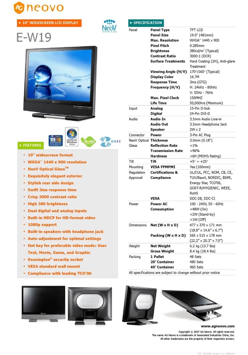
AG Neovo E-W19 User manual
AG Neovo
AG Neovo HX-32E User manual

AG Neovo
AG Neovo HX-32 User manual
AG Neovo
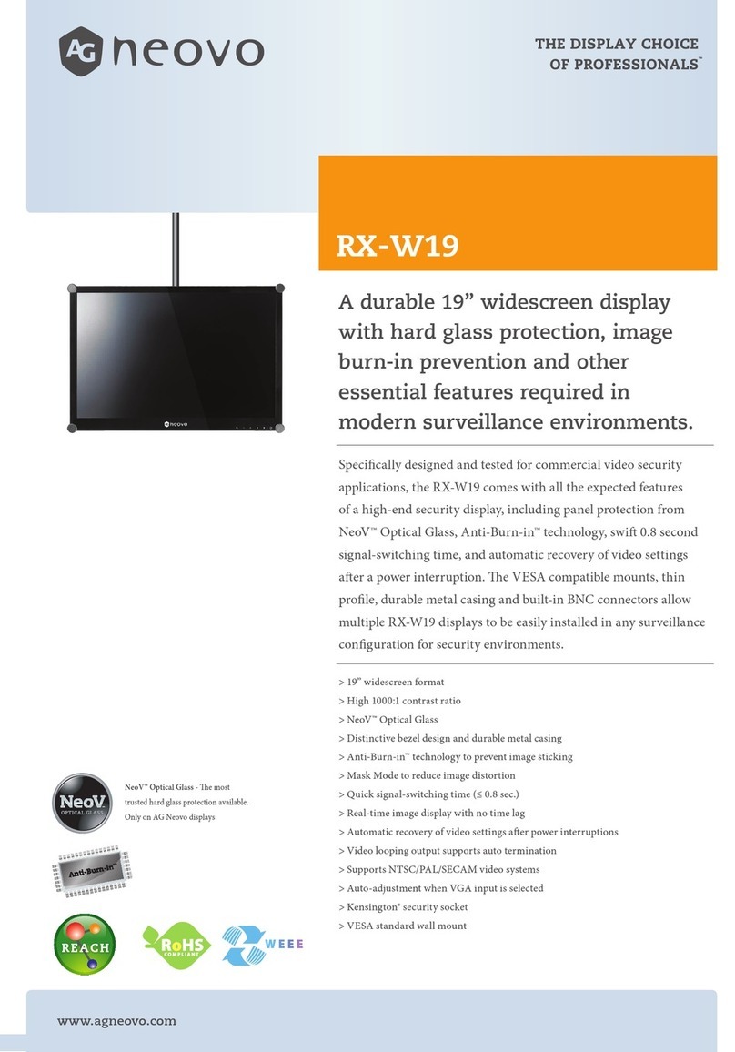
AG Neovo RX-W19 User manual
AG Neovo
AG Neovo M-15V User manual

AG Neovo
AG Neovo PS Series User manual

AG Neovo
AG Neovo F-217 User manual
AG Neovo
AG Neovo QM-43 User manual
AG Neovo
AG Neovo F-15 User manual
AG Neovo
AG Neovo U-17 User manual

AG Neovo
AG Neovo SC-17 User manual
AG Neovo
AG Neovo SC-19 User manual

AG Neovo
AG Neovo SX-19P User manual

