AGA marvel M18SZ Manual

Installation
Operation
and
Maintenance
Instructions
Built In
Wine Cellars
M18SZ
M24SZ
M24DZ
MPRO24DZ
Note: Wine Cellars are designed exclusively for the storage of
wine. Wine Cellars cannot aain storage temperatures suitable
for fresh food storage.
2
is committed to building a quality product
in an environmentally friendly manner. Our processes are
tightly controlled and closely monitored. We have achieved
certications in ISO 9001 for quality assurance, ISO 14001
for environmental management, and OHSAS 18001 for oc-
cupational health and safety from Lloyd’s Register Quality
Assurance.
NOTE
!CAUTION
Important Safety Instructions
Warnings and safety instructions appearing in this guide
are not meant to cover all possible conditions and situa-
tions that may occur. Common sense, caution, and care
must be exercised when installing, maintaining, or operat-
ing this appliance.
Recognize Safety Symbols,
Words, and Labels.
!WARNING
WARNING-Hazards or unsafe practices with
high probability of personal injury or property / prod-
uct damage.
CAUTION-Hazards or unsafe practices which could
result in personal injury or property or product damage.
NOTE-Important information to help assure a problem
free installation and operation.
CONTENTS
Unpacking the wine cellar .....................................................3
Tools required ..................................................................3
Warranty registration ...........................................................4
Dimensions for M(XX)SZ with Glass Door ...........................5
Dimensions for M24DZ with Glass Door ...............................6
Dimensions for M24DZ with Glass Overlay Door...................7
Dimensions for MPRO24DZ with Glass Door .......................8
Pre installation considerations ............................................9
Rough in opening ...........................................................9
Select location ................................................................9
Electrical requirements .................................................10
Corner installation .........................................................10
Installing the cabinet .........................................................11
Anti tip bracket considerations .......................................11
Leveling the unit ................................................................12
Installing the power module ..............................................12
Placing power module on top of cabinet .........................12
Power module electrical connections .............................13
Installing the grille .............................................................14
Custom Grille and Door Overlay Panels ............................17
Mounting Grille Overlay Panel ......................................17
Overlay Door Panel Instructions ....................................18
Hinge and gasket adjustments ..........................................20
Installing side panels .........................................................21
Installing the kickplate .......................................................21
Installation checks ............................................................22
Common installation errors ..............................................22
Use and care guide ...........................................................23
Operation of your wine cellar ...........................................23
Defrosting .......................................................................24
Cleaning .........................................................................24
Condenser cleaning procedure ......................................24
Energy saving tips .............................................................25
Product sounds ................................................................25
Troubleshooting guide ......................................................26
Obtaining service ..............................................................26
Warranty ...........................................................................27
!WARNING
State of California Proposition 65 Warning:
This product contains one or more chemicals known
to the State of California to cause cancer.
!WARNING
State of California Proposition 65 Warning:
This product contains one or more chemicals known
to the State of California to cause birth defects or
other reproductive harm..
3
!CAUTION
!WARNING
EXCESSIVE WEIGHT HAZARD
Use two or more people to move product.
Failure to do so can result in back or other injury.
Remove Interior Packaging
Your wine cellar has been packed for shipment with all
parts that could be damaged by movement securely fas-
tened. Remove internal packing materials and any tape
holding internal components in place. The owners manual
is shipped inside the product in a plastic bag along with the
warranty registration card, and other accessory items.
Important
Keep your carton and packaging until your wine cellar has
been thoroughly inspected and found to be in good condi-
tion. If there is damage, the packaging will be needed as
proof of damage in transit. Afterwards please dispose of all
items responsibly in particular the plastic bags which can
be a suffocation hazard.
Note to Customer
This merchandise was carefully packed and thoroughly
inspected before leaving our plant. Responsibility for its
safe delivery was assumed by the retailer upon acceptance
of the shipment. Claims for loss or damage sustained in
transit must be made to the retailer.
DO NOT RETURN DAMAGED MERCHANDISE TO THE
MANUFACTURER - FILE THE CLAIM WITH THE RE-
TAILER.
If the power module was shipped or has been laying on
its side for any period of time allow the power module to
sit upright for a period of at least 24 hours before plugging
in. This will assure oil returns to the compressor. Plugging
the power module in immediately may cause damage to
internal parts.
UNPACKING YOUR WINE CELLAR
Tools to have available for installation:
• Phillips screwdriver
• Flat blade screwdriver
• Hex head nut drivers size 1⁄4" and 5⁄16"
• Level
• Drill and drill bit (#6 - .204)
• Open end wrenchs size 1⁄4", 7⁄16" and 1⁄2"
• Slip joint pliers
• Adjustable wrench
• Tape measure
• Hex socket and ratchet size 7⁄16"
• 3/32" Hex key (Allen wrench)
Help Prevent Tragedies
Child entrapment and suffocation are not problems of
the past. Junked or abandoned refrigerators are still
dangerous even if they sit out for "just a few days".
If you are getting rid of your old freezer, please follow
the instructions below to help prevent accidents.
Before you throw away your old refrigerator:
•Take off the doors or remove the drawers
•Leave the shelves in place so children may not easily
climb inside.
!WARNING
4
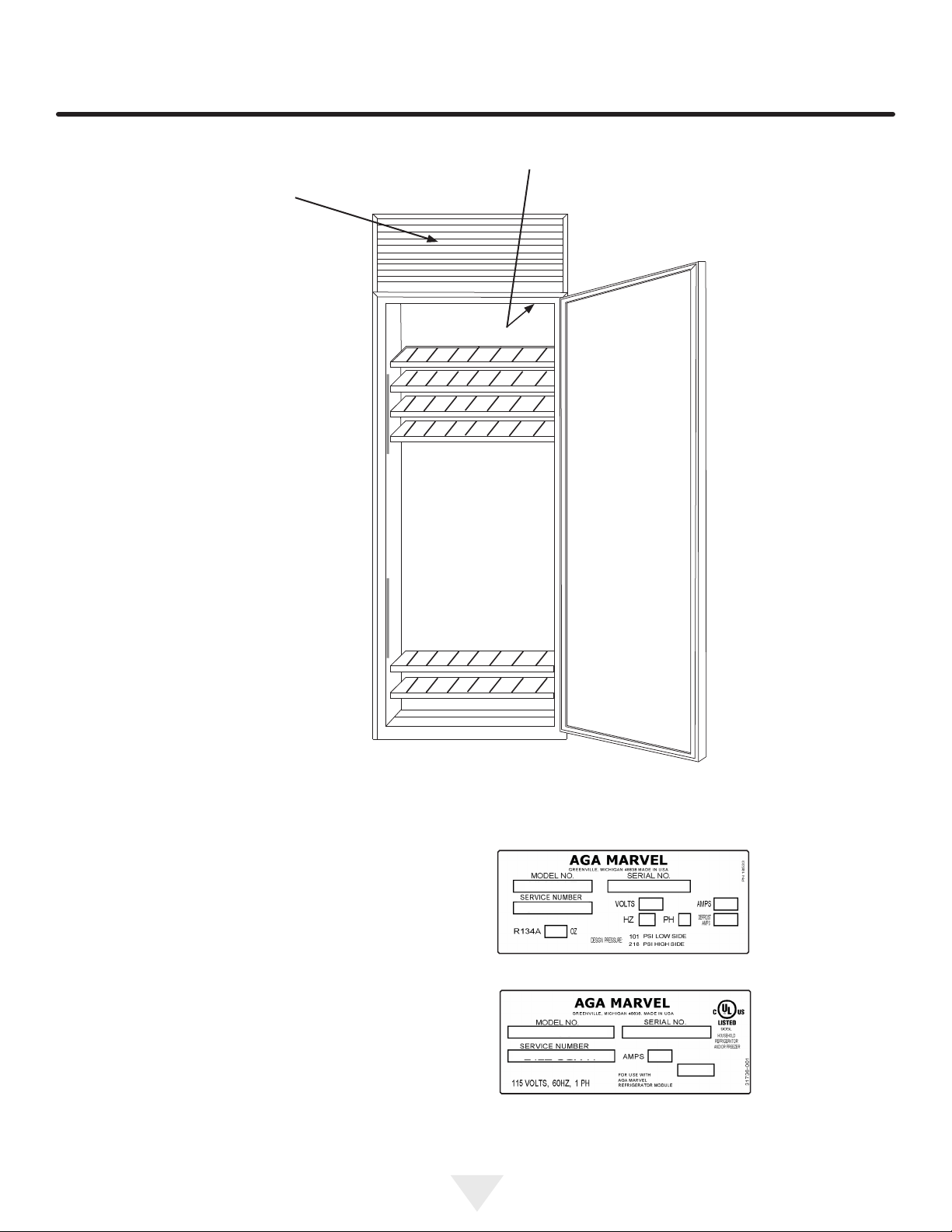
Power module serial
plate is behind the
grille on the front of
the power module-
Cabinet serial plate is on the
inside top liner toward the right
side-
It is important you send in your warranty registration card
immediately after taking delivery of your wine cellar.
The following information will be required when registering
your unit.
Service Number
Serial Number
Date of Purchase
Dealer’s name and address
The service number and serial number can be found on the
serial plates which are located on the power module and
the cabinet. See gure 1 above for locations.
Warranty Registration
Figure 2
Power module
serial plate
Figure 3
Cabinet
serial plate
Figure 1
Serial plate
locations
WARRANTY REGISTRATION

5
PRODUCT DIMENSIONS FOR M(XX)SZ WITH GLASS DOOR
1⁄2"
(12.7mm)
1⁄2"
(12.7mm)
73" to 735⁄8"
(185.4cm to 187cm)
251⁄8"
(63.8cm)
197⁄8"
(50.5cm) To kickplate
To face of door
84" to 845⁄8"
(213.4cm to 214.9cm)
241⁄2"
(62.2cm)
273⁄16"
(69.1cm)
"B"
"C"
"A"
11"
(27.9cm)
29⁄16"
(6.5cm)
Electrical Requirements:
A grounded 115 volt, 60 cycle, single phase, 15 amp
dedicated circuit is required. Follow all local building codes
when installing electrical and unit.
MODEL "A" "B" "C"
M18SZ-BGX 18" (45.7cm) 17" (43.2cm) 4111⁄16" (105.9cm)
M24SZ-BGX 24" (61cm) 23" (58.4cm) 4711⁄16" (121.1cm)
This manual suits for next models
3
Table of contents
Languages:
Other AGA marvel Wine Cooler manuals

AGA marvel
AGA marvel Refrigerated Wine Cellar 3SWCE User manual

AGA marvel
AGA marvel MP15WS Manual

AGA marvel
AGA marvel 3BARM Manual

AGA marvel
AGA marvel ML24WSG0 Series Manual

AGA marvel
AGA marvel 6SDZE Manual

AGA marvel
AGA marvel ML15WS Manual

AGA marvel
AGA marvel MP24WSG0LS Manual
 Manual")
AGA marvel
AGA marvel 30WCM (Marvel) Manual

AGA marvel
AGA marvel MP24WSG0 Manual

AGA marvel
AGA marvel 6BARM Manual
 Manual")


