manuals.online logo
Brands
  1. Home
  2. •
  3. Brands
  4. •
  5. AGA
  6. •
  7. Ventilation Hood
  8. •
  9. AGA Rangemaster FM900 Manual

AGA Rangemaster FM900 Manual

Contents:
1 Introduction
2 Important Information
3 Extraction Performance
4 Installation
5 Operating Instructions
6 Maintenance
7 General Arrangement Drawings
1. INTRODUCTION
During the cooking process, there will be heat, vapours and
fumes produced. Your FM900 built in extractor has been
designed to complement your kitchen both in looks and
performance in order to create a good environment for creative
cooking and is ideal for applications where a conventional
cooker hood is neither suitable nor desirable, for example, in
an inglenook chimney or kitchen furniture above the hob.
2. IMPORTANT INFORMATION
The exhaust air must not be discharged into a flue which is
used for exhausting fumes from appliances supplied with
energy other than electricity e.g. oil or gas-fired central heating
boilers, gas-fired water heaters, etc.
Requirements of the relevant authorities concerning the
discharge of exhaust air must be complied with.
Pay particular attention to fire risk when frying. To minimise
the risk of fire, all instructions relating to cleaning the grease
filters and removing grease deposits must be adhered to.
Do not flambé under the extractor.
The minimum clearance between the top of the hob or
cooker and the bottom of the extractor should be within
the following range (unless a greater distance is specified by
your cooking appliance or furniture manufacturer):
 hob-to-extractor minimum clearance distances:
450mm above electric hobs and cookers
650mm above gas hobs and cookers
760mm above wok burners, griddles, barbeques.
 hob-to-extractor clearance (max recommended): 900mm
The minimum distance between the hob and the bottom of the
extractor is essential for safety reasons and to prevent
overheating of the extractor and its components.
The maximum distance between the hob and the bottom of
the extractor is required to ensure that the extractor collects
the cooking fumes and odours efficiently.
Please also note that a 90o bend in 150mm flexible ducting will
require 215mm minimum headroom to give a smooth radius
with no kinking.
You are advised to install measures designed to reduce
the incidence of cold draughts entering the property via
any ductwork.
 For extractors with internal fans this should, at the
very least, consist of an external duct termination
with integrated non-return flaps (e.g. gravity shutter
wall grille/louvre).
3. EXTRACTION PERFORMANCE
The primary influence on the overall performance of the
extractor is the design of the ducting which takes the exhaust
air from the extractor to the outside. The duct route should be
a prime consideration during the initial stages of the kitchen
design (We do not recommend recirculating air back into the
kitchen, however, recirculating versions or conversion kits are
available if absolutely necessary).
Please note the following:
 Easy access to the duct route during installation is
important. Lack of access may require the “blind” fitting of
flexible ducting, with increased risk of unseen kinks and
impaired efficiency.
 The extractor is provided with a spigot suitable for
connecting 150mm diameter ducting.
 Note: the cross-sectional area of 150mm diameter ducting
is the minimum area consistent with efficient extraction.
Reducing the duct size seriously reduces performance.
 The most efficient configuration is to duct straight through
an outside wall so try to position the cooker against an
outside wall when designing your kitchen.
 Well installed, correctly sized rigid round ducting, or an
equivalent flat channel system will usually perform best,
with round semi-rigid (like flue liner) being a very good
alternative. Flexible (foil or plastic film) ducting is
economical but its use should be minimised as it gives the
worst performance and should only be used for very short
duct runs or initial connection and should be pulled taut to
prevent significant losses in extraction efficiency.
 For maximum efficiency, ducting should be kept as short
and as straight as possible. Bends in the duct will degrade
performance so the number of bends in a duct run should
be kept to a minimum and be gradual and smooth to
prevent turbulence. Avoid kinks in flexible ducting, pulling it
WARNING
Proper care must be taken to ensure that the negative
pressures caused by high performance extraction
systems do not adversely affect the safe operation of
certain types of fuel-burning appliances (gas, oil or solid
fuel), including those installed in the kitchen and
possibly also those installed in other parts of the house.
Where such fuel-burning appliances are installed,
adequate ventilation MUST be provided in the room of
installation, located and sized such that the negative
pressure in the room created by the extractor does not
exceed 4Pa.
In case of doubt, do not operate the extractor and fuel-
burning appliance(s) simultaneously and consult an
appropriate (for the fuel type) expert for advice.
ELECTRICAL SAFETY
This appliance requires an earth connection.
Ensure that the supply voltage corresponds to that
marked on the rating label inside the extractor.
The extractor must be isolated from the electrical supply
before carrying out any cleaning or maintenance
operations.
FM900
Built-In Extractor
Installation, Operation and Maintenance Instructions
FM900 Built In Extractor
Installation, Operating & Maintenance Instructions
W0645 Aga Rangemaster FM900 (energy label version) O&M Jan 15.docx Page 2 AGA Rangemaster
taut over straight runs to ensure that the internal surface is
as smooth as possible.
 If using rigid ducting we recommend that the initial duct
connection to the extractor spigot is made using semi-rigid
round ducting to allow for any positioning errors and easy
disconnection in the event of maintenance.
4. INSTALLATION
The FM range of built in extractors are designed to slot into a
cut-out/opening made in a horizontal soffit panel (usually the
underside of kitchen furniture or inglenooks/chimney
arrangements).
 A panel thickness of at least 15mm must be provided into
which an opening can be made and the unit fixed.
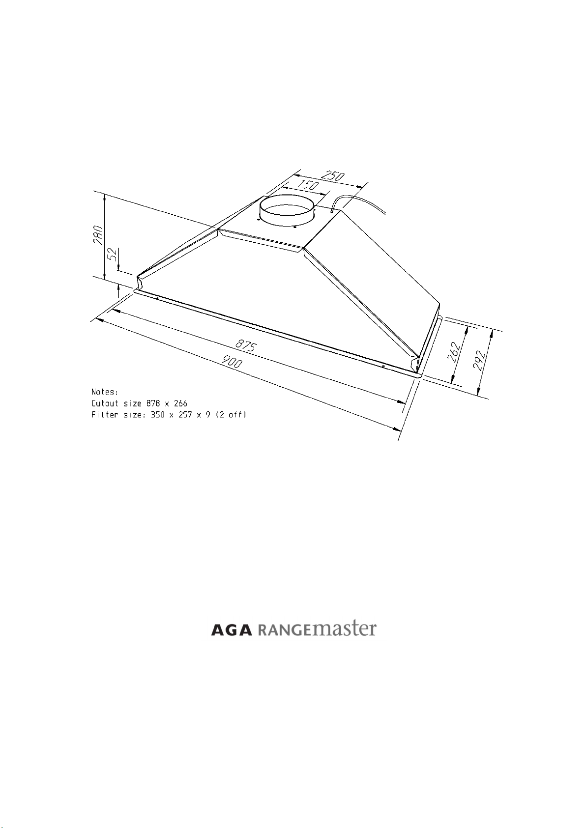
4.1. Prepare Opening
Prepare an opening where the extractor is to be installed.
Detailed dimensioned drawings showing the extractor layout
can be found in Section 8 "General Arrangements Drawing" to
help you with this.
4.2. Duct Installation
Make holes, as necessary, in the walls or ceiling to take the
ducting from the extractor exhaust spigot location to the
outside.
Note: A 175mm diameter hole is suitable for both ducting and
any electrical cables (such as power or remote fan cables) to
pass through.
Depending upon your installation you may need to run the
ducting before or after the extractor is in place, however, all
holes must be made in advance to avoid debris entering the
appliance.
The duct route length should be kept as short as possible with
as few bends as possible (see Section 3).
If terminating on an outside wall a suitable weather louvre
should be fitted. A variety of ducting components and
complete kits are available to suit most installations.
For roof or chimney duct terminations please contact Aga
Rangemaster or seek alternative specialist advice.
 Recirculating Models
We do not recommend recirculating air installations and they
should be avoided wherever possible (see section 3).
If your extractor has been adapted for recirculation (not the
standard configuration) then adequate provision must be
made for exhausted air to return into the kitchen (at least
equivalent to 125mm diameter round duct) - e.g. ducted out
through the top of the cabinet. Failure to do so may cause the
unit to overheat and fail and will invalidate your warranty.
4.3. Electrical Installation
The extractor is a stationary appliance designed to be
connected by fixed wiring to the electrical supply. A competent
electrical technician must perform the electrical installation.
The hood must be fed from a dedicated 230Vac single
phase electrical supply terminated with a switched spur
fitted with a 3A fuse. The spur should be located adjacent to
the hood/cooker so that the supply can be disconnected from
the hood using the switch. The means of disconnection from
the supply must have a minimum contact separation of 3mm
in all poles. Alternatively, a means of disconnection in the
fixed wiring according to the relevant wiring rules must be
fitted.
For your convenience you may wish to terminate the electrical
supply from the switched, fused spur with a standard UK 3 pin
240V socket positioned close to the extractors intended
location.
The extractor can then be fitted with a standard 240V 3 pin
plug so that it can be plugged in to the switched supply by the
appliance installer.
Should you wish to wire the appliance directly into the
switched, fused spur then a supply cord for connecting the
spur to the extractor is included. The mains supply is
connected to the free end of this cord as follows:
INCOMING SUPPLY CORD CONNECTIONS
Core
Core Colour
Live Brown
Neutral Blue
Protective Earth Green/Yellow
4.4. Connecting the Ducting
Terminate the ducting where it exits the building. If using a
wall mount weather louvre secure the ducting to the louvre
spigot and attach the louvre to the wall. Ensure that the air fins
are directed downwards. If you are fitting an alternative
termination ensure that the ducting is secure.
If using expanding foam make sure that any flexible ducting is
supported internally to prevent it crushing where foamed.
Pull flexible ducting back along its route such that it is as
smooth as possible. Position the extractor face down and as
close to the opening as is practical and cut off excess before
connecting the ducting to the extractor exhaust spigot using
plastic tie straps or a suitable alternative (e.g. jubilee clip) - do
not use duct tape as the sole means of connection.
Note: The FM900 has integral non-return flaps as part of the
spigot assembly to reduce air blowing back into the unit from
outside. Take care not to obstruct these flaps when
connecting flexible ducting. The flaps are designed to
supplement the provisions you make in your ductwork to
prevent draughts. You may remove these flaps if you are
concerned they will catch on your ductwork provided that other
measures to control draughts have been installed.
Check that the duct has not been flattened or kinked.
4.5. Fixing the Extractor in Position
 Fixing the extractor safely into position requires two people
so do not start if assistance is unavailable.
 Remove the grease filters as described in Section 6 to
prevent damage whilst manoeuvring the product.
 Fixing holes are located in the extractor fixing flange – see
Section 8 "General Arrangements Drawing". The extractor
is held securely in place by screws into the soffit panel
through these holes.
 Check that the electrical supply chord has been
connected, that power is switched off and that the ducting
is securely fastened to the spigot.
 Push the extractor up through the prepared opening and
mark the positions of the fixing holes.
Take care not to crush or introduce undesirable
bends/kinks in the ducting when pushing the extractor into
place.
ELECTRICAL HAZARD
DISCONNECT ELECTRICAL SUPPLY
BEFORE PROCEEDING FURTHER
FM900 Built In Extractor
Installation, Operating & Maintenance Instructions
W0645 Aga Rangemaster FM900 (energy label version) O&M Jan 15.docx Page 3 AGA Rangemaster
 Because the fixing holes are close to the edge of the soffit
cut-out it is recommended that pilot holes are drilled for the
fixing screws.
 Secure the extractor in place using the screws supplied or
suitable alternatives for your panel and cut-out
arrangement.
 One person should hold the unit in place whilst pilot holes
and screws are installed by an assistant – do not attempt
this on your own.
Note: Consider whether it is possible to build in provisions for
accessing the ducting with the unit in place - this may simplify
installation because ducting can be connected when the unit is
in position and will enable easier straightening of duct,
inspection and removal of the unit in the event of future
service.
 Should you wish to remove the extractor then you will
require two people to safely undertake this work.
The removal process is the reverse of installation.
One person should hold the unit and prevent it falling
whilst an assistant removes the screws securing it in place.
Once the screws are removed both people can carefully
lower the appliance from the opening, taking care not to
damage the extractor or ducting in the process.
Tip: You may wish to positioned a platform on the hob
(such as a cardboard box) to place the extractor onto
because the connected ducting may not be long enough to
reach the work surface below.
FM900 Built In Extractor
Installation, Operating & Maintenance Instructions
W0645 Aga Rangemaster FM900 (energy label version) O&M Jan 15.docx Page 4 AGA Rangemaster
5. OPERATING INSTRUCTIONS
 Switch on the power at the fused spur.
 The extractor has 6 pushbuttons, which illuminated when
pressed. Their functions are described below:
6. MAINTENANCE
Regular maintenance is essential to ensure good
performance and long-life.
To maintain the immaculate appearance of the extractor,
and to minimise fire risk, ensure that grease deposits on
the extractor surfaces are kept to a minimum by regular
cleaning.
To clean the stainless steel surfaces of the extractor, use a
soft cloth and a suitable cleaning agent, such as a specially
produced stainless steel cleaner or washing up detergent
and warm water.
Painted surfaces should be cleaned using a soft cloth,
detergent and warm water.
Glass surfaces should be cleaned with a suitable glass
cleaning agent.
 Do not use abrasive cleaning materials or products.
 Do not use bleach based cleaning materials or
products.
Clean the grease filters in a dishwasher or by hand-
washing in hot water and detergent every 2 months -
sooner if the extractor is used extensively and filters
become grease laden.
 Whilst you can expect years of service from mesh
grease filters, they are considered a consumable item
and may deteriorate over time and need replacement,
particularly when cleaned in a dishwasher. For
dishwasher users adhering to a 2 monthly cleaning
interval we recommend grease filter replacement every
5 years to maintain optimum performance, even if they
show no visible signs of deterioration. For all users,
filters should be replaced whenever they exhibit signs
of physical wear.
6.1. Removing the Grease Filters
The filters have an integrated sprung latch and release
mechanism.
Release the latch by pulling the lever and remove the filter.
The filter is replaced by locating the fixed tabs on the filter into
corresponding slots in the extractor base and then pushing the
filter into position with the latch held open. Once the filter is in
position carefully release the lever, allowing the latch to
engage.
6.2. Replacing Lamps
The LED lamps are not designed for end user replacement.
7. SPECIFICATIONS
FM900 Built
-
In Extraction Canopy
Airflow, nominal in free air
800
m
3
/hr
Fan spigot diameter
150mm
Width
900mm
Depth
292mm
Height
280mm
Supply Voltage:
230V~ 50Hz
Power input: Fan
2
75
W
Lighting:
Natural White LED
:
12V, 2
.6
W
Light Quantity
2
Total power:
2
81
W
Protective Fuse Sizes for Electrical Supply
3A
CAUTION
To minimise the risk of fire, all instructions relating
to cleaning the grease filters and removing grease
deposits must be adhered to.
Pushbutton Functions
(for models with pushbutton controls)
The extractor controller automatically switches off
the appliance if there has been no operator action
for 4 hours.
After 30 hours accumulated running GREASE
FILTER CLEANING will be signalled by all 6
indicators flashing. Reset by pressing Push-button
FAN OFF (delay).
Lights ON/OFF
Motor ON - SPEED 1
Motor OFF
Motor ON – TIMED INTENSIVE MODE
(Reverts automatically to speed
3
after 5 minutes
)
Motor ON - SPEED 3
Maximum Speed for Normal Use
Motor ON - SPEED 2
Motor RUN ON TIMER
(OFF after 10 minutes to clear fumes)
For more detailed specification and energy
efficiency information please refer to the
product fiche for your product
FM900 Built In Extractor
Installation, Operating & Maintenance Instructions
W0645 Aga Rangemaster FM900 (energy label version) O&M Jan 15.docx Page 5 AGA Rangemaster
8. GENERAL ARRANGEMENT DRAWING
Clarence Street, Royal leamington Spa,
Warwickshire, CV31 2AD, England.
Tel: +44 (0) 1926 457400 Fax: +44 (0) 1926 450526
E-mail: [email protected]
www.agarangemaster.com
Customer Services: 0870 789 5107
Technical Queries: 0870 589 5105

Other AGA Ventilation Hood manuals

AGA AMCHD44SS User manual

AGA

AGA AMCHD44SS User manual

AGA Cooker hood User manual

AGA

AGA Cooker hood User manual

AGA AEXT 720 (72) User manual

AGA

AGA AEXT 720 (72) User manual

AGA Falcon FALHDS90BL/-AUS User manual

AGA

AGA Falcon FALHDS90BL/-AUS User manual

AGA VENTILATION HOOD Parts list manual

AGA

AGA VENTILATION HOOD Parts list manual

AGA AMCHD36SS User manual

AGA

AGA AMCHD36SS User manual

AGA AMCHD36 User manual

AGA

AGA AMCHD36 User manual

AGA PH890 Guide

AGA

AGA PH890 Guide

AGA AMCHD36SS User manual

AGA

AGA AMCHD36SS User manual

AGA UNBHDS90 User manual

AGA

AGA UNBHDS90 User manual

AGA SH890 Guide

AGA

AGA SH890 Guide

AGA 1000 SE Instruction manual

AGA

AGA 1000 SE Instruction manual

AGA ARAFX30W5SS User manual

AGA

AGA ARAFX30W5SS User manual

AGA ATHOOD User manual

AGA

AGA ATHOOD User manual

Popular Ventilation Hood manuals by other brands

Concept2 OPK5160bc manual

Concept2

Concept2 OPK5160bc manual

New World 70 Chim Hood User & installation instructions

New World

New World 70 Chim Hood User & installation instructions

BLUE STONE HOB-8748 user manual

BLUE STONE

BLUE STONE HOB-8748 user manual

Air King AX Series operating manual

Air King

Air King AX Series operating manual

Concept2 OPK4590bc manual

Concept2

Concept2 OPK4590bc manual

V-ZUG DIAS 10 operating instructions

V-ZUG

V-ZUG DIAS 10 operating instructions

Concept2 OPP2260 manual

Concept2

Concept2 OPP2260 manual

ROROS HETTA EDGE-12 manual

ROROS HETTA

ROROS HETTA EDGE-12 manual

Air King ESAPDQ Series IMPORTANT INSTRUCTIONS and OPERATING MANUAL

Air King

Air King ESAPDQ Series IMPORTANT INSTRUCTIONS and OPERATING MANUAL

Range Master RMPE user manual

Range Master

Range Master RMPE user manual

Air King GRAN30SS Use and handling instructions

Air King

Air King GRAN30SS Use and handling instructions

KStar K1035 operating instructions

KStar

KStar K1035 operating instructions

Air King AV1426 operating manual

Air King

Air King AV1426 operating manual

Blue Star PL Series Installation and use & care

Blue Star

Blue Star PL Series Installation and use & care

Air King Range Hood SEV30SSH Specifications

Air King

Air King Range Hood SEV30SSH Specifications

Junker JD69SE52 Instructions for installation and use

Junker

Junker JD69SE52 Instructions for installation and use

Beef Eater BRC214SA Assembly and operating instructions

Beef Eater

Beef Eater BRC214SA Assembly and operating instructions

V-ZUG DV 5 operating instructions

V-ZUG

V-ZUG DV 5 operating instructions

manuals.online logo
manuals.online logoBrands
  • About & Mission
  • Contact us
  • Privacy Policy
  • Terms and Conditions

Copyright 2025 Manuals.Online. All Rights Reserved.