AGATE TECHNOLOGY AT-2040 User manual

AGATE TECHNOLOGY AT-2040
OPERATOR MANUAL
PORTABLE TRANSDUCER TEST SET

(951) 719-1032
1
AGATE TECHNOLOGY AT-2040 OPERATOR MANUAL
Introduction:
This manual is intended to inform the operating user on product specifications, setup, troubleshooting,
and operation procedures on the AT-2040. The AT-2040 is designed as a rugged, completely self-
contained, battery powered, vibration sensor test set. The AT-2040 is meant for use in the field or
laboratory for the verification of control room working conditions or to verify the performance of
vibration transducers.
The AT-2040 consists of an internal charger, battery, main power amplifier, charge converter,
electrodynamic shaker, NIST traceable reference, internal computer, signal generation board, and LCD
screen display.
Block Diagram
Charger: Internal charger which operates between 110v and 220v for worldwide power support.
Battery: 6 Amp Hour, Sealed, Lead Acid battery. FAA transport approved.
Power Amplifier: Takes the input signal from the Signal Generator and is used to drive the
electrodynamic shaker.

(951) 719-1032
2
AGATE TECHNOLOGY AT-2040 OPERATOR MANUAL
Electrodynamic Shaker: Produces 4.5 lbf pk of sine force and is made with carbon fiber composite and
isolated linear bearings. This provides low distortion when shaking the transducer load.
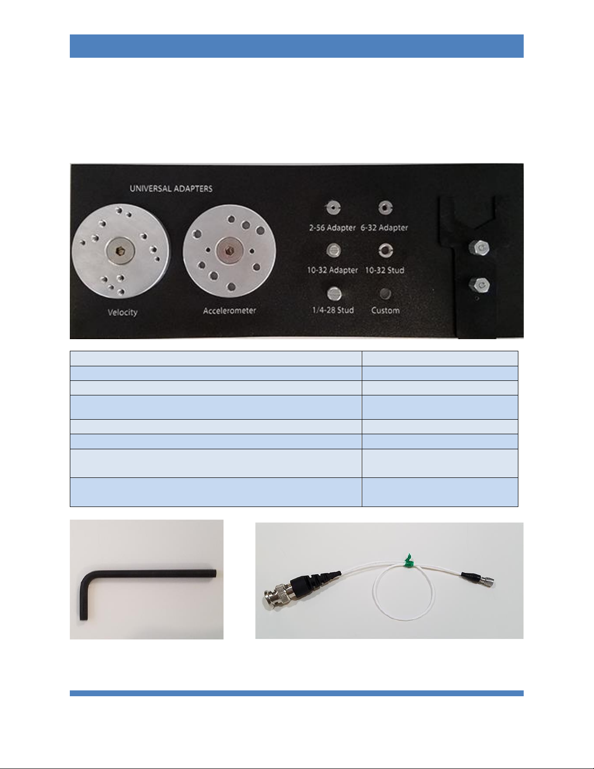
Reference Accelerometer: NIST traceable calibration standard accelerometer with ¼-28 tapped
mounting hole.
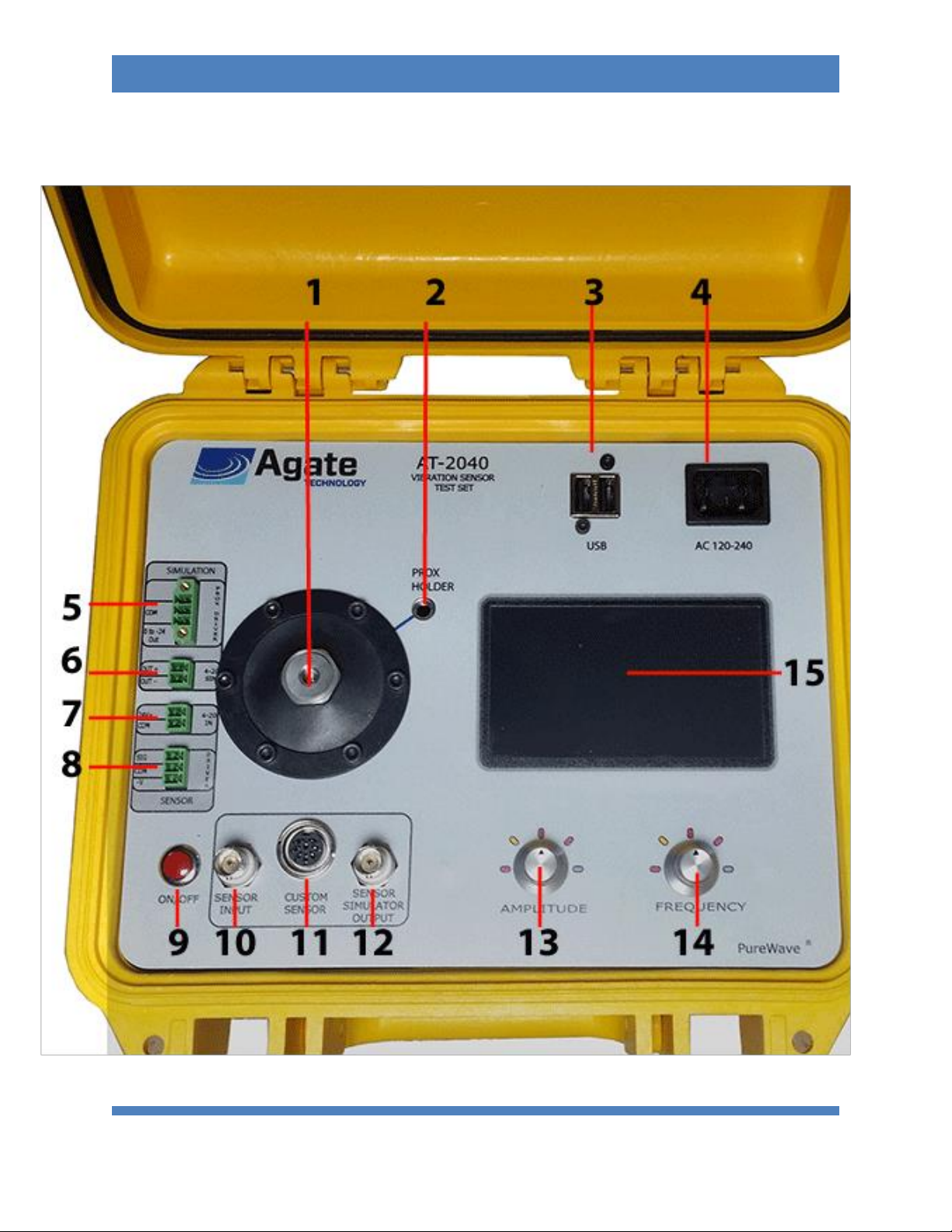
Computer: 1 GHz Cortex-A8 processor, 512 MB DDR3 RAM, 20GB of storage memory included, with USB
and network connectivity.
Charge Converter: For direct input of charge mode accelerometers
Signal Generation Board: Consists of multiple amplifiers and channels selectable by internal relays. This
is categorized into three different applications.
1. The Power Amplifier Output: To control the vibration of the electrodynamic shaker at
the amplitude and frequency set by the user.
2. Input: To read in sensitivity of multiple transducer types.
3. Signal Generator: To output a wide range of simulated voltage and current
measurements.
LCD Screen: Color 4.3 inch LCD 480x272 resolution display with resistive touch screen.
Primary Functions of the AT-2040:
•To shake or excite a transducer under test.
In shake mode, AT-2040 can be used as a variable frequency, variable amplitude shaker.
In this mode, the frequency and amplitude are set manually by the user, while the
computer provides high accuracy measurement signals.
•To calculate transducer sensitivity.
By comparing signals sent to the reference accelerometer by the signal generation
board and the signals returned by the transducer under test, the AT-2040 can
automatically determine test transducers sensitivity to a high level of accuracy.
•To produce a NIST traceable calibration certificate.
Once the sensitivity has been calculated and saved across the test transducer’s
frequency range, the AT-2040 will produce a NIST traceable certificate and graph in PDF
format. This certificate is stored into the computer’s memory, or recalled and exported
anytime to USB.
•To simulate a transducer using a precision signal generator (function generator).

(951) 719-1032
3
AGATE TECHNOLOGY AT-2040 OPERATOR MANUAL
The AT-2040 is capable of producing signals over a wide amplitude and frequency using
its built in amplifiers to simulate a variety of charge and voltage signals. This allows the
user to simulate a working transducer and is the ideal tool for electronics testing,
troubleshooting, or calibrating condition monitoring systems.
Warnings on Shaker Operation
•AT-2040 is designed for vertical use. Operating in the horizontal position is possible as the
shaker element has linear bearings for support, but the load should not exceed 400 Grams.
•This instrument may shake violently at high amplitude and low frequency. Always make sure to
keep the unit secure and operate on a stable surface.
•When amplitude or frequency has exceeded their acceptable ranges, the unit will issue a
warning or shut down depending on the operating conditions.
•Even when closed, this instrument is not waterproof. Never use near water.
•Failure to hold the accelerometer with the short handle wrench when attaching and removing
transducers can cause permanent shaker damage.
Note about battery operation:
AT-2040 is powered by one 6 amp hour, sealed lead acid, rechargeable battery as its primary power
source. This battery is designed to be continuously charged at a trickle rate once the battery reaches
100%. Battery life will depend on USB plugins, payload weight, along with shaker driving force. In low
power conditions, AT-2040 uses approximately 0.4 amps of power making it possible to achieve 13
hours of battery power. However, the unit will shut down premature to full discharge preventing
damage and ensuring long term battery life. During long periods of high power consumption, AT-2040
may only last up to one hour. A battery light indicator is located in the top menu bar and turns from
green to red as the battery becomes low on energy. Next to the battery bar, is an approximate
percentage of battery remaining based on the following voltage chart:

(951) 719-1032
4
AGATE TECHNOLOGY AT-2040 OPERATOR MANUAL
The portable shaker unit may be operated with the power plugged in. The AC charger will supply battery
charge when plugged in, however charge rate will be greatly increased when the unit is powered off.
•For best results use the shaker when batteries are fully charged
•Automatic power management will automatically turn off before full battery discharge. This is a
protective measure to ensure longer battery operating life.
•If deep discharge occurs, the battery charger is set to recharge over two or more days. This is
normal operation to prevent battery damage.

(951) 719-1032
5
AGATE TECHNOLOGY AT-2040 OPERATOR MANUAL
Accessories:
The AT-2040 comes standard with the following accessories (pictured):
Short Handle Aluminum Wrench
(ACC-100)
¼-28 Stud
(MNT-104)
10-32 Stud
(MNT-105)
2-56 Adapter
(MNT-106)
6-32 Adapter
(MNT-107)
10-32 Adapter
(MNT-111)
Universal Velocity Mounting Adapter with ¼-28 mounting
hex screw
(MNT-112)
Universal Accelerometer Mounting Adapter with ¼-28
mounting hex screw
(MNT-113)
5/32 Hex L-Wrench (ACC-101) 10-32 to BNC adapter cable for sensitivity measurement (CAB-100)

(951) 719-1032
6
AGATE TECHNOLOGY AT-2040 OPERATOR MANUAL
AC Power Cord 120v (PWR-100) OR AC Power Cord 220-240v (PWR-101)
Optional Accessories Include:
Chadwick-Helmuth Velocimeter
(CAB-101)
IEPE Accelerometer 2 pin Mil
(CAB-102)
IEPE Accelerometer 3 pin Mil
(CAB-103)
Replacement studs 3 of each: 1/4-28, 10-32. Adapters 2-
56, 6-32, 10-32
(MNT-100)
1/4-28 Adapter
(MNT-108)
Mounting Stud 1/4-28 to 8-32
(MNT-109)
Adapter 1/4-28M to 3/8-24F
(MNT-110)
Proximity Probe Adapter Kit
(PRX-100)
Proximity Probe Proximity adapters M6 to 3/8
(PRX-101)
Steel Target
(PRX-102)
*Custom made cables or platform mounts can be made to your specifications based on
transducer sample or datasheet, please contact us for more information.
PHYSICAL OVERVIEW:

(951) 719-1032
7
AGATE TECHNOLOGY AT-2040 OPERATOR MANUAL

(951) 719-1032
8
AGATE TECHNOLOGY AT-2040 OPERATOR MANUAL
1) Reference adapter and mounting location for test transducers. ALWAYS use the short handle wrench
provided, otherwise twisting force will be applied directly to the electrodynamic shaker.
2) Proximity probe mounting location –Sold as an addon accessory.
3) Dual USB port for data transfer or accessory power.
4) 120-240 plug in for plug provided with the unit.
5) Proximity probe simulation plugin –capable of providing a test signal between 0 and -24 volts.
6) 4-20Ma simulation plugin –capable of providing a test signal between 4 and 20 Milliamps.
7) Input for sensitivity test of 4-20ma transducers and vibration transmitters.
8) Proximity probe driver input for radial and axial measurement. (Includes built-in -24v power for
driver.)
9) Push button On/Off switch.
10) BNC Sensor input sensor for sensitivity test. Supports Charge, IEPE, Proximity Probes and Velocity
sensors.
11) Custom Sensor In/Out –See rear view pinout diagram.
1) Charge.
2) Ground.
3) 5-10 Volt output (adjustable).
4) Channel A –Input for transducers that provide voltage outputs.
5) Channel B- Triax.
6) Channel C –Triax.
7) Test Signal.
8) Displacement input.
12) BNC Sensor Simulator Output; Simulates a variety of transducer types using adjustable voltage and
supply currents. Types include the following: IEPE charge, -24 Proximity Probe, 4-20ma supply.
13) Amplitude adjustment button, also serves as back button when pressed.
14) Frequency adjustment button, also serves as select button when pressed.
15) Color, resistive touch screen.

(951) 719-1032
9
AGATE TECHNOLOGY AT-2040 OPERATOR MANUAL
Software Update Installation:
AT-2040 features software update support to load in sensor information, custom databases,
bug fixes, software add-ons and more.
1) To update your unit to the most current software visit
www.agatetechnology.com/upgrade
2) Load the program Agate.up onto your USB drive and insert into the unit with power off.
3) Power on the AT-2040 device and wait for the upgrade prompt.
4) Select “Yes” to upgrade and the software will begin to unpack and install.
5) When completed remove the USB stick and AT-2040 will automatically restart.
Operations:
•Powering the unit on and off:
oPress and Hold the red On/Off switch for 1 second, the unit will begin its startup
sequence.
oPress and hold the red On/Off switch for 5 seconds. When the screen turns blank, the
unit has powered down.

(951) 719-1032
10
AGATE TECHNOLOGY AT-2040 OPERATOR MANUAL
Main Menu:
Main Menu
Shaker Button
•Manual Shake Screen
Sensitivity Test Button
•Auto or Manual Test Selection Screen
oManufacture Selection Menu
oSensor Selection Menu
oReview
oAuto Test
▪Graph View
▪Table View
▪Shake View
•Manual Test Screen
Setup Button
•Time and Time Zone
•Screen Timeout
•User and Company Configuration
•Recall Previous Test
oExport PDF to USB
•Impact Sensor Information
•Set Screen Contrast
•About With Software Disclaimer
Simulation Button
•Manufacture Selection Menu
oSensor Selection Menu
oReview Setup
oRun

(951) 719-1032
11
AGATE TECHNOLOGY AT-2040 OPERATOR MANUAL
The main selection menu is split into four subsections:
Shake: To manually test a transducer or equipment by only using variable frequency and amplitude.
Test: To test transducer sensitivity, by either manual adjustment or automatic plot.
Setup: Customize AT-2040 options to your preferences.
Simulation: Simulate the signal of a transducer.

(951) 719-1032
12
AGATE TECHNOLOGY AT-2040 OPERATOR MANUAL
Shake:
To manually test a transducer or equipment by only using variable frequency and amplitude:
Step 1) From the main screen: Select “Shake”
Step 2) Select your sensor and mount it to the ¼-28 drill hole in the reference accelerometer.
Hold the reference accelerometer with the provided short handle wrench and screw in the
sensor at the same time. When necessary, use the correct sensor adapter for your size.
From this screen you will be able to adjust frequency and amplitude. Press down on the frequency knob
or select from the touch screen to begin.
Tap the units bar on the left side under the amplitude to change units.
Tap on the right side to change between Hz and RPM
As the AT-2040 is adjusted the three vertical bars will indicate its status.
OUT: The percentage of maximum output supplied by the main amplifier.
THD: Total Harmonic Distortion.
Mils: Displacement range of the electromagnetic shaker in mils.

(951) 719-1032
13
AGATE TECHNOLOGY AT-2040 OPERATOR MANUAL
Test:
To test sensor sensitivity first select manual or automatic mode.
If manual mode is selected, a sensitivity screen is displayed with manual frequency and amplitude
adjust. The transducer sensitivity is displayed in the lower right.
If automatic mode is selected, AT-2040 will display the list of included sensor specs from the built in
library.
Step 1) Select the Manufacture
Step 2) Select your sensor from the Manufacture list.
Step 3) Review specs such as weight and sensitivity to make sure your sensor matches.

(951) 719-1032
14
AGATE TECHNOLOGY AT-2040 OPERATOR MANUAL
Step 4) Test: From here your sensor will be automatically stepped through the predetermined
plot points and graphed. Afterwards, the certification can be saved into memory and exported
to USB in PDF format.
While the auto test is running, the shaker will change the test colors from Red to Blue to Green.
This signifys the following:
Red: Starting
Blue: Testing
Green: Completed

(951) 719-1032
15
AGATE TECHNOLOGY AT-2040 OPERATOR MANUAL
Setup:
The setup menu consists of multiple options to accommodate user preferences. This is where you will be
able to export to USB and select the following:
•Date and Time Zone.
•Screen Time Out.
•User and Company Names.
•Calibrate Touch Screen
•Setup the network
To recall a previous test and save PDF to USB:
*** IMPORTANT NOTE: YOU MUST POWER ON AT-2040 WITH THE USB STORAGE
DEVICE INSERTED INTO THE USB HUB TO SAVE A RECORD. OTHERWISE AT-2040 WILL NOT BE
ABLE TO LOAD THE USB DRIVER. IF YOU ARE HAVING PROBLEMS WITH AT-2040 READING
YOUR DEVICE RESTART THE UNIT WITH THE DEVICE PLUGGED IN.
1) In setup menu, Select PDF. This will bring you to the Test Review menu where you may delete or
export your previous test.
2) Select the test record that you wish to transfer to USB by checking the box to the left of the
sensor save. From here, you may export to CSV or create a PDF certificate. If you wish to delete
this record, select the delete button.

(951) 719-1032
16
AGATE TECHNOLOGY AT-2040 OPERATOR MANUAL
You will be notified of a successful export by “Save Complete.” You can then remove the USB
and review your test.
1 –Sample of Generated Report

(951) 719-1032
17
AGATE TECHNOLOGY AT-2040 OPERATOR MANUAL
Simulation:
AT-2040 has the ability to simulate a transducer signal without the actual sensor being present.
Step 1) Select the sensor manufacture from the built in library
Step 2) Select the transducer to be tested from the manufacture list.

(951) 719-1032
19
AGATE TECHNOLOGY AT-2040 OPERATOR MANUAL
Optional Step When Connecting Wirelessly: Enter the ESSID and Password as shown:
Skip this step if connecting by hard wire ethernet
Make sure the wireless adapter is connected and restart the unit.
Step 3) Identify Shaker IP address. This can be found under the network menu as displayed below:
Table of contents
Other AGATE TECHNOLOGY Test Equipment manuals