Agate AT-2040 User manual

AGATE TECHNOLOGY
AT-2040
OPERATOR MANUAL
PORTABLE TRANSDUCER TEST SET
(951) 719-1032
1
AGATE TECHNOLOGY AT-2040 OPERATOR MANUAL
Introduction:
This manual is intended to inform the operating user on product specifications, setup, troubleshooting,
and operation procedures on the AT-2040. The AT-2040 is designed as a rugged, completely self-
contained, battery powered, vibration sensor test set. The AT-2040 is meant for use in the field or
laboratory for the verification of control room working conditions or to verify the performance of
vibration transducers.
The AT-2040 consists of an internal charger, battery, main power amplifier, electrodynamic shaker, NIST
traceable reference, internal computer, signal generation board, and LCD screen display.
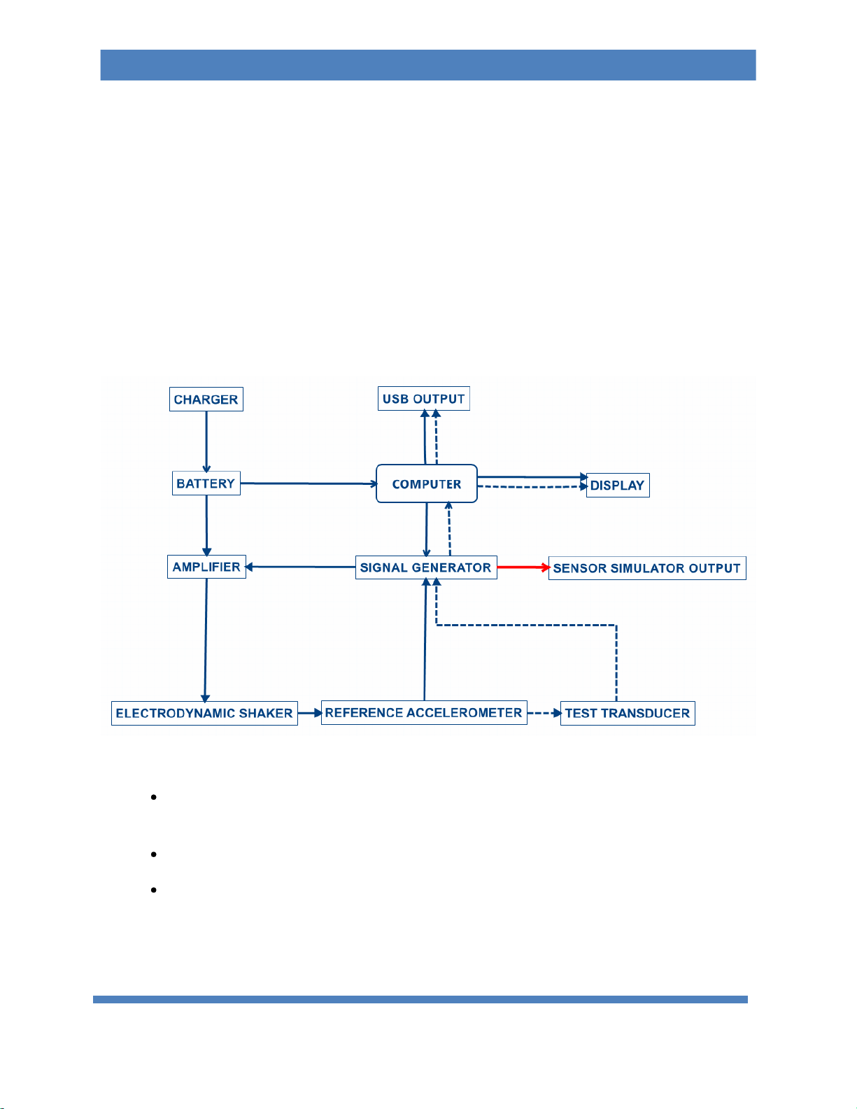
Block Diagram
Charger: Internal charger which operates between 110v and 220v for worldwide power
support.
Battery: 5 Amp Hour, Sealed, Lead Acid battery. FAA transport approved.
Power Amplifier: Takes the input signal from the Signal Generator and is used to drive the
electrodynamic shaker.

(951) 719-1032
2
AGATE TECHNOLOGY AT-2040 OPERATOR MANUAL
Electrodynamic Shaker: Produces 4.5 lbf pk of sine force and is made with carbon fiber
composite and isolated linear bearings. This provides low distortion when shaking the
transducer load.
Reference Accelerometer: NIST traceable calibration standard accelerometer with ¼-28
tapped mounting hole.
Computer: 1 GHz Cortex-A8 processor, 512 MB DDR3 RAM, 20GB of storage memory
included, with USB and network connectivity.
Signal Generation Board: Consists of multiple amplifiers and channels selectable by internal
relays. This is categorized into three different applications.
a. The Power Amplifier Output: To control the vibration of the electrodynamic
shaker at the amplitude and frequency set by the user.
b. Input: To read in sensitivity of multiple transducer types.
c. Signal Generator: To output a wide range of simulated voltage and current
measurements.
LCD Screen: Color 4.3 inch LCD 480x272 resolution display with resistive touch screen.
Primary Functions of the AT-2040:
oTo shake or excite a transducer under test.
In shake mode, AT-2040 can be used as a variable frequency, variable amplitude shaker.
In this mode, the frequency and amplitude are set manually by the user, while the
computer provides high accuracy measurement signals.
oTo calculate transducer sensitivity.
By comparing signals sent to the reference accelerometer by the signal generation
board and the signals returned by the transducer under test, the AT-2040 can
automatically determine test transducers sensitivity to a high level of accuracy.
oTo produce a NIST traceable calibration certificate.
Once the sensitivity has been calculated and saved across the test transducer’s
frequency range, the AT-2040 will produce a NIST traceable certificate and graph in PDF
format. This certificate is stored into the computer’s 4GB memory, or recalled and
exported anytime to USB.

(951) 719-1032
3
AGATE TECHNOLOGY AT-2040 OPERATOR MANUAL
oTo simulate a transducer using a precision signal generator (function generator).
The AT-2040 can produce signals over a wide amplitude and frequency using its built-in
amplifiers to simulate a variety of charge and voltage signals. This allows the user to
simulate a working transducer and is the ideal tool for electronics testing,
troubleshooting, or calibrating condition monitoring systems.
Warnings on Shaker Operation
AT-2040 is designed for vertical use. Operating in the horizontal position is possible as the
shaker element has linear bearings for support, but the load should not exceed 400 Grams.
This instrument may shake violently at high amplitude and low frequency. Always make sure to
keep the unit secure and operate on a stable surface.
When amplitude or frequency has exceeded their acceptable ranges, the unit will issue a
warning or shut down depending on the operating conditions.
Even when closed, this instrument is not waterproof. Never use near water.
Failure to hold the accelerometer with the short handle wrench when attaching and removing
transducers can cause permanent shaker damage.
Note about battery operation:
AT-2040 is powered by one 5-amp hour, sealed lead acid, rechargeable battery as its primary power
source. This battery is designed to be continuously charged at a trickle rate once the battery reaches
100%. Battery life will depend on USB plugins, payload weight, along with shaker driving force. In low
power conditions, AT-2040 uses approximately 0.4 amps of power making it possible to achieve 13
hours of battery power. However, the unit will shut down premature to full discharge preventing
damage and ensuring long term battery life. During long periods of high power consumption, AT-2040
may only last up to one hour. A battery light indicator is in the top menu bar and turns from green to
red as the battery becomes low on energy. Next to the battery bar, is an approximate percentage of
battery remaining based on the following voltage chart:

(951) 719-1032
4
AGATE TECHNOLOGY AT-2040 OPERATOR MANUAL
The portable shaker unit may be operated with the power plugged in. The AC charger will supply battery
charge when plugged in, however charge rate will be greatly increased when the unit is powered off.
For best results use the shaker when batteries are fully charged
Automatic power management will automatically turn off before full battery discharge. This is a
protective measure to ensure longer battery operating life.
If deep discharge occurs, the battery charger is set to recharge over two or more days. This is
normal operation to prevent battery damage.

(951) 719-1032
5
AGATE TECHNOLOGY AT-2040 OPERATOR MANUAL
Accessories:
The AT-2040 comes standard with the following accessories (pictured):
Short Handle Aluminum Wrench
(ACC-100)
¼-28 Stud
(MNT-104)
10-32 Stud
(MNT-105)
2-56 Adapter
(MNT-106)
6-32 Adapter
(MNT-107)
10-32 Adapter
(MNT-111)
Universal Velocity Mounting Adapter with ¼-28 mounting
hex screw
(MNT-112)
Universal Accelerometer Mounting Adapter with ¼-28
mounting hex screw
(MNT-113)
5/32 Hex L-Wrench (ACC-101) 10-32 to BNC adapter cable for sensitivity measurement (CAB-100)
(951) 719-1032
6
AGATE TECHNOLOGY AT-2040 OPERATOR MANUAL
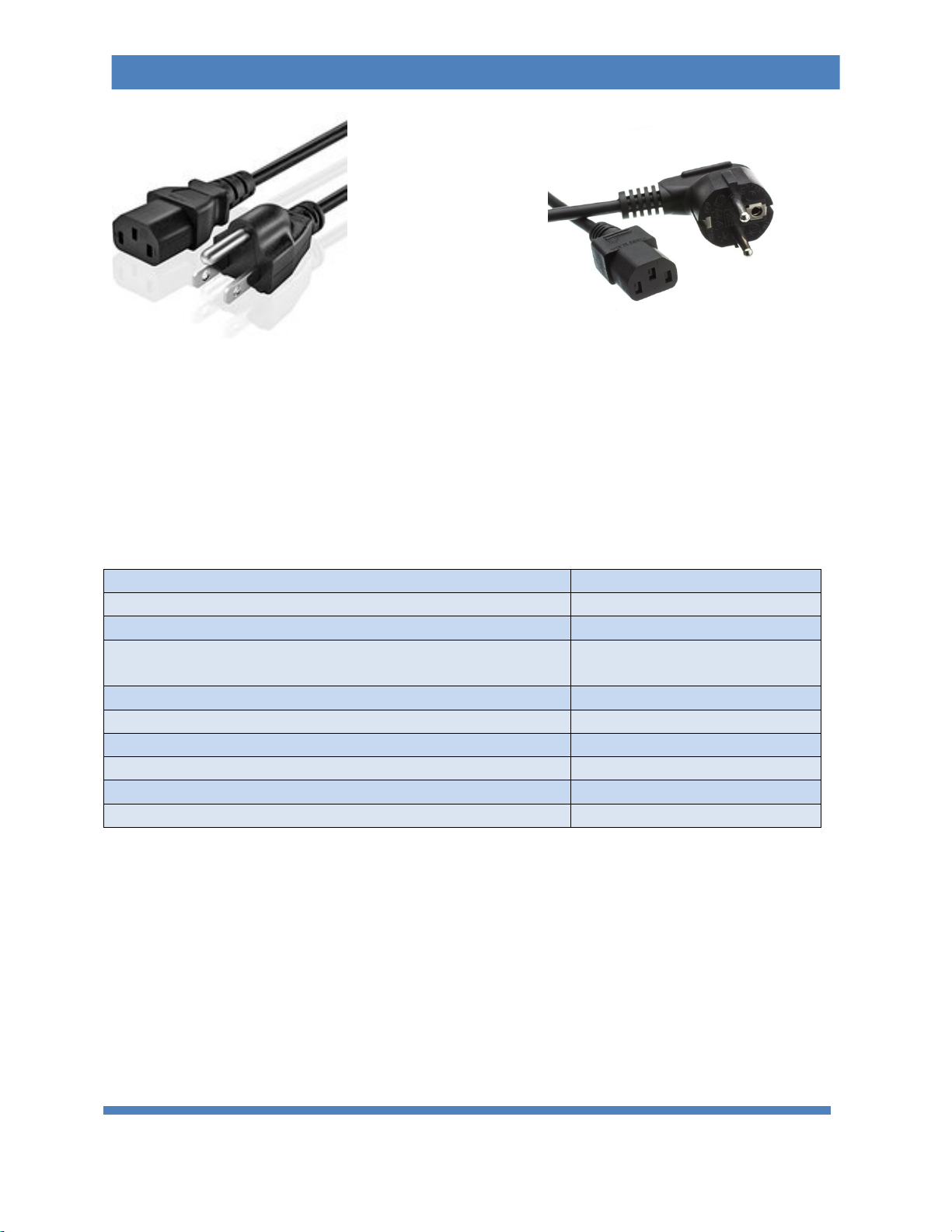
AC Power Cord 120v (PWR-100) OR AC Power Cord 220-240v (PWR-101)
Optional Accessories Include:
Chadwick-Helmuth Velocimeter
(CAB-101)
IEPE Accelerometer 2 pin Mil
(CAB-102)
IEPE Accelerometer 3 pin Mil
(CAB-103)
Replacement studs 3 of each: 1/4-28, 10-32. Adapters 2-
56, 6-32, 10-32
(MNT-100)
1/4-28 Adapter
(MNT-108)
Mounting Stud 1/4-28 to 8-32
(MNT-109)
Adapter 1/4-28M to 3/8-24F
(MNT-110)
Proximity Probe Adapter Kit
(PRX-100)
Proximity Probe Proximity adapters M6 to 3/8
(PRX-101)
Steel Target
(PRX-102)
*Custom made cables or platform mounts can be made to your specifications based on
transducer sample or datasheet, please contact us for more information.
(951) 719-1032
7
AGATE TECHNOLOGY AT-2040 OPERATOR MANUAL

(951) 719-1032
8
AGATE TECHNOLOGY AT-2040 OPERATOR MANUAL
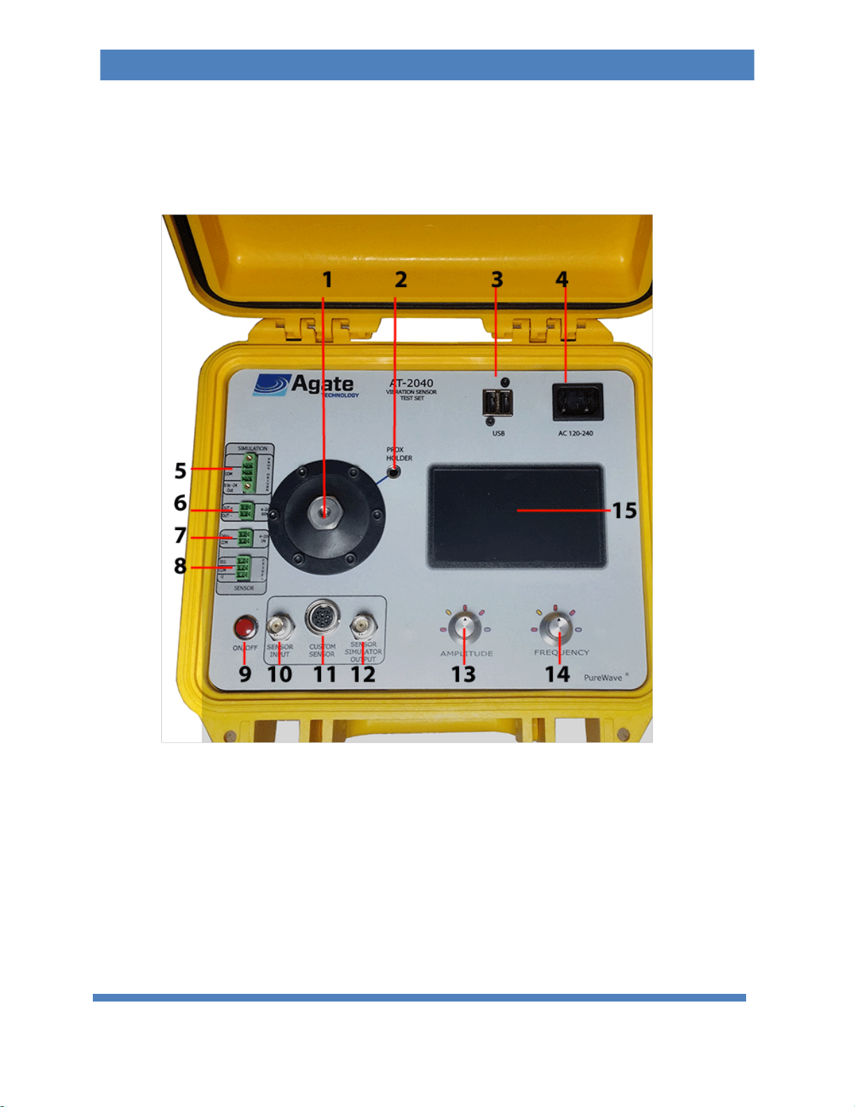
PHYSICAL OVERVIEW:
1) Reference adapter and mounting location for test transducers. ALWAYS use the short handle wrench
provided, otherwise twisting force will be applied directly to the electrodynamic shaker.
2) Proximity probe mounting location – Sold as an addon accessory.
3) Dual USB port for data transfer or accessory power.
4) 120-240 plug in for plug provided with the unit.
5) Proximity probe simulation plugin – capable of providing a test signal between 0 and -24 volts.
6) 4-20Ma simulation plugin – capable of providing a test signal between 4 and 20 Milliamps.
7) Input for sensitivity test of 4-20ma transducers and vibration transmitters.
8) Proximity probe driver input for radial and axial measurement. (Includes built-in -24v power for
driver.)
9) Push button On/Off switch.
10) BNC Sensor input sensor for sensitivity test. Supports Charge, IEPE, Proximity Probes and Velocity
sensors.
11) Custom Sensor In/Out – See rear view pinout diagram.
1) Charge.
2) Ground.
3) 5-10v output (adjustable)
4) Channel A – Input for transducers that provide voltage outputs.
5) Channel B- Triax.
6) Channel C – Triax.
7) Test Signal.
8) Displacement input.
12) BNC Sensor Simulator Output; Simulates a variety of transducer types using adjustable voltage and
supply currents. Types include the following: IEPE charge, -24 Proximity Probe, 4-20ma supply.
13) Amplitude adjustment button, also serves as back button when pressed.
14) Frequency adjustment button, also serves as select button when pressed.
15) Color, resistive touch screen.

(951) 719-1032
9
AGATE TECHNOLOGY AT-2040 OPERATOR MANUAL
Software Update Installation:
AT-2040 features software update support to load in sensor information, custom databases,
bug fixes, software add-ons and more.
1. To update your unit to the most current software, visit:
www.agatetechnology.com/upgrade
2. Load the program Agate.up onto your USB drive and insert the drive into the unit
while the power is off.
3. Power on the AT-2040 device and wait for the upgrade prompt.
4. Select “Yes” to upgrade and the software will begin to unpack and install.
5. When completed remove the USB stick and AT-2040 will automatically restart.
Operations:
Powering the unit on and off:
oPress and Hold the red On/Off switch for 1 second, the unit will begin its startup
sequence.
oPress and hold the red On/Off switch for 5 seconds. When the screen turns blank, the
unit has powered down.
Other manuals for AT-2040
1
Table of contents
Other Agate Test Equipment manuals

Popular Test Equipment manuals by other brands


Redtech
Redtech TRAILERteck T05 user manual

Venmar
Venmar AVS Constructo 1.0 HRV user guide

Test Instrument Solutions
Test Instrument Solutions SafetyPAT operating manual

Hanna Instruments
Hanna Instruments HI 38078 instruction manual

Kistler
Kistler 5495C Series instruction manual

Waygate Technologies
Waygate Technologies DM5E Basic quick start guide

StoneL
StoneL DeviceNet CK464002A manual

Seica
Seica RAPID 220 Site preparation guide

Kingfisher
Kingfisher KI7400 Series Training manual

Kurth Electronic
Kurth Electronic CCTS-03 operating manual

SMART
SMART KANAAD SBT XTREME 3G Series user manual

Agilent Technologies
Agilent Technologies BERT Serial Getting started