Elektror D 03 M Product guide
Elektror airsystems gmbh
Hellmuth-Hirth-Strasse 2, D-73760 Ostfildern
Postfach 1252, D-73748 Ostfildern
Telefon +49 (0)711 31973-0
Telefax +49 (0)711 31973-5000
info@elektror.de
www.elektror.de
ND
D 03 M, E 03, D 04 M, E 04, D 045 M, E 045, D 05 M, E 05, D 052 M, E 052,
D 060, E 060, D 064, E 064, D 066, E 066, D 07, D 072, D 08, D 082, D 09, D 092,
2D 04, 2D 045, 2D 05, 2D 052, 2D 060, 2D 064, 2D 066, 2D 07, 2D 08
Elektror Nieder-
druckventilatoren
Betriebs- und
Montageanleitung
DE
Elektror Low
Pressure Blowers
Operating and
assembly
instructions
EN

2
Typ Nr.
kW cos kW cos
Hz min-1 min-1 Hz
Mot. EN 60034-1 IP W-Kl.F
V V
A A
D-73760 Ostfildern
Germany
DE
Betriebs- und Montageanleitung ND www.elektror.de
016303 03.14/09
INHALT
1 ANGABEN ÜBER DIE MASCHINE
2 INFORMATIONEN ÜBER TRANSPORT,
HANDHABUNG UND LAGERUNG DER MASCHINE
3 INFORMATIONEN ÜBER DIE INBETRIEBNAHME
4 ANGABEN ZU BETRIEB UND VERWENDUNG
5 ANGABEN ZUR INSTANDHALTUNG
6 SICHERHEITSRELEVANTE INFORMATIONEN ÜBER
AUSSERBETRIEBNAHME UND ABBAU
7 HAFTUNG UND HAFTUNGSAUSSCHLUSS
8 EINBAUERKLÄRUNG NACH ANHANG II 1 B
9 EXPLOSIONSZEICHNUNG
10 ALLGEMEINE ERSATZTEILLISTE
11 TECHNISCHE DATEN
12 ANGABEN GEMÄSS ERP DURCHFÜHRUNGS-
VERORDNUNG 327/2011
Diese Betriebs- und Montageanleitung muß dem Bedie-
nungspersonal jederzeit zugänglich sein. Lesen Sie die vor-
liegende Betriebs- und Montageanleitung vor Montage und
Inbetriebnahme des Ventilators sorgfältig durch.
Änderungen vorbehalten. Im Zweifelsfall ist eine Rückspra-
che mit dem Hersteller erforderlich. Diese Unterlage ist urhe-
berrechtlich geschützt. Sie darf ohne unsere ausdrückliche
schriftliche Zustimmung Dritten nicht zugänglich gemacht
werden. Jede Form der Vervielfältigung oder Erfassung und
Speicherung in elektronischer Form ist untersagt.
1 ANGABEN ÜBER DIE MASCHINE
Bitte entnehmen Sie unsere Anschrift dem Deckblatt.
Bitte entnehmen Sie den Gültigkeitsbereich dieser Betriebs-
und Montageanleitung der enthaltenen Einbauerklärung
nach Anhang II 1 B.
Die auf Seite 18 ff. dargestellten technischen Daten gelten
für die Serienausführung. Ihr Ventilator kann davon abwei-
chen (siehe Leistungsschild). In diesem Falle beachten Sie
bitte die mitgelieferten zusätzlich gemeinsam geltenden Un-
terlagen oder die dann geltende, eigene Betriebs- und Mon-
tageanleitung.
Leistungsschild
Für Anschluß, Wartung und Bestellung von Ersatzteilen sind
ausschließlich die Daten auf dem Leistungsschild maßgeb-
lich. Dem Leistungsschild ist auch die Serien-Nummer des
Gerätes und dessen Herstellungsjahr zu entnehmen.
1.1 Bestimmungsgemäße Verwendung
Die Ventilatoren eignen sich ausschließlich zum Fördern von
gasförmigen Medien ohne Feststoffe.
Im Fördermedium enthaltene Feststoffe oder Verunreinigun-
gen müssen vor Eintritt in den Ventilator ausgefiltert werden.
Bei Kondensatbildung empfehlen wir eine Kondenswasser-
bohrung an der tiefsten Stelle im Gehäuse.
Der Einsatz für
• aggressive,
• abrasive,
• klebende,
• giftige,
• explosionsfähige oder
• sehr feuchte
Medien ist nicht zulässig.
Die maximale Temperatur des Fördermediums darf bei der
Serienausführung -20°C bis +80°C nicht überschreiten. Son-
derausführungen mit Temperatursperre bis max. 180°C. Im
Fördermedium enthaltene Feststoffe oder Verunreinigungen
müssen vor Eintritt in den Ventilator ausgefiltert werden. Die
maximale Umgebungstemperatur darf bei der Serienausfüh-
rung +60° C nicht überschreiten.
Der Ventilator ist nicht für die Auftstellung im Freien geeignet.
Der Ventilator ist grundsätzlich für S1-Betrieb (Dauerbetrieb)
ausgelegt. Davon abweichend sind maximal 30 Schaltungen
pro Stunde zulässig.
Der Ventilator eignet sich in der Serienausführung nicht für
die Aufstellung in oder Förderung von explosionsfähiger At-
mosphäre.
Sonderausführungen für den Einsatz außerhalb der oben
beschriebenen Anwendungen stehen auf Anfrage zur Verfü-
gung. Umbau und Veränderungen des Ventilators sind nicht
zulässig. Bei Sondergeräten sind die Hinweise in den zusätz-
lich beigelegten Zusatzbetriebs- und Montageanleitungen zu
beachten und einzuhalten. Sie weichen in einzelnen Punkten
von dieser Betriebs- und Montageanleitung ab.
Elektror-Ventilatoren zeichnen sich durch ein hohes Maß an
Betriebssicherheit aus. Da es sich bei den Ventilatoren um
sehr leistungsfähige Maschinen handelt, sind zur Vermei-
dung von Verletzungen, Beschädigungen von Sachen und
der Maschine selbst, folgende Sicherheitshinweise streng zu
beachten.
1.2 Mechanische Gefährdungen
Mechanische Gefährdungen sind an den Elektror-Ventila-
toren dem Stand der Technik und den Anforderungen des
Sicherheits- und Gesundheitsschutzes entsprechend mini-
miert. Um handhabungsbedingte Restrisiken auszuschlie-
ßen, empfehlen wir, in allen Lebensphasen des Gerätes ge-
eignete Schutzausrüstung einzusetzen bzw. zu tragen (bitte
beachten Sie die Hinweise im Folgenden).
1.3 Gefährdung durch Hineinfassen und unerwarteten
Anlauf
Durch rotierende Teile besteht im Inneren des Gerätes im
Betrieb hohes Verletzungsrisiko. Setzen Sie das Gerät vor
dem Öffnen, Hineinfassen oder Einführen von Werkzeugen
in jedem Falle ausser Betrieb und warten Sie den Stillstand
aller bewegten Teile ab. Sichern Sie das Gerät während des
gesamten Zeitraumes zuverlässig gegen Wiederanlauf ab.
Stellen Sie ebenfalls sicher, dass keine Gefährdungssitu-
ation in Folge eines Wiederanlaufes nach einem Stillstand
entsteht, z.B. in Folge einer Energie-Unterbrechung oder
Blockade.
1.4 Gewicht, sicherer Stand
Insbesondere während Transport und Aufstellung bestehen
Gefährdungen durch Umstürzen oder Herabfallen. Siehe 2.1
– Transport und Handhabung, sowie 3.1 – Aufstellen, Mon-
tage.
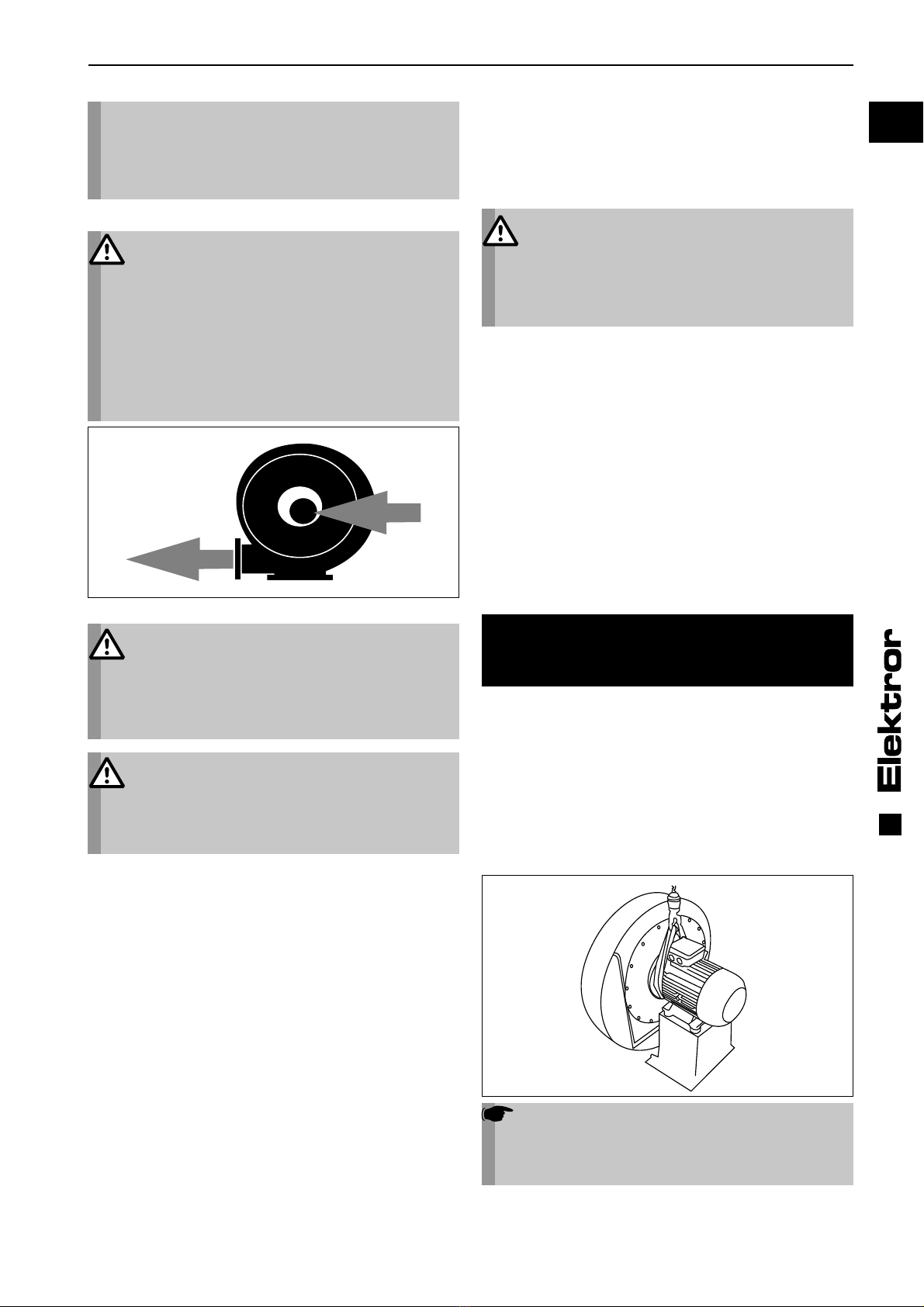
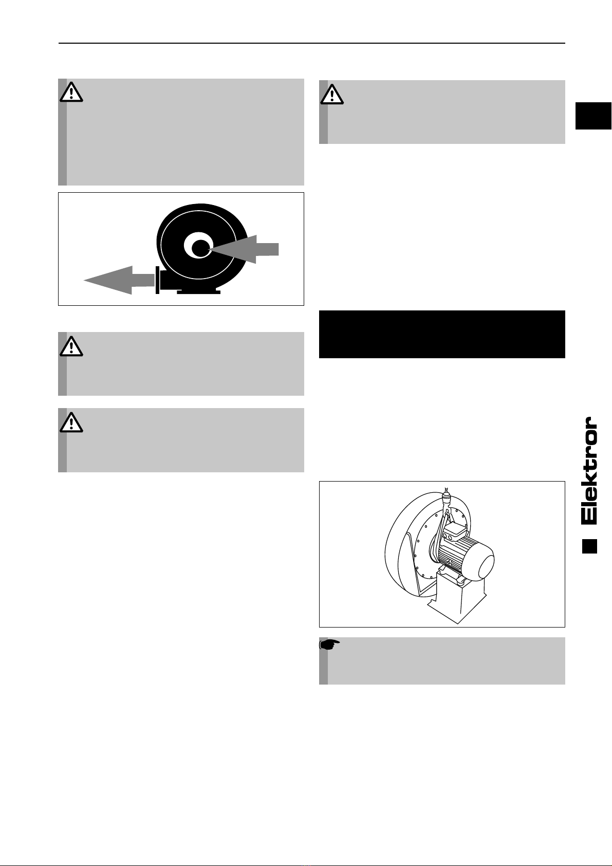
1.5 Ansaugwirkung
Ventilatoren erzeugen eine starke Saugwirkung.
Warnung!
Am Ansaugstutzen können Gegenstände, Klei-
dungsstücke und auch Haar angesaugt werden.
Verletzungsgefahr!
3
DE
www.elektror.de Betriebs- und Montageanleitung ND
016303 03.14/09
Während des Betriebs nicht in der Nähe der
Ansaugöffnung aufhalten. Der Ventilator darf nie
mit offenem Ansaugstutzen betrieben werden und
muß daher mit einem Schutzgitter nach DIN EN
ISO 13857 abgedeckt werden.
(Verletzungsgefahr durch Laufrad!).
1.6 Ausblaswirkung
Warnung!
Sehr starke Ausblaswirkung am Ausblasstutzen.
Angesaugte Gegenstände können mit hoher
Geschwindigkeit heraus geschleudert werden
(Verletzungsgefahr!).
Ventilatoren eignen sich ausschließlich zum För-
dern von Reinluft. Um das Ansaugen von Fremd-
körpern oder Verunreinigungen, die ausgeblasen
werden könnten, zuverlässig zu verhindern,
müssen diese unbedingt vor Eintritt in den Venti-
lator ausgefiltert werden.
Nicht in den Ausblasstutzen hineingreifen!
1.7 Temperatur
Warnung!
Das Ventilatorgehäuse nimmt während des
Betriebs die Temperatur des Fördermediums an.
Wenn diese über +50°C liegt, muß der Ventilator
vom Betreiber vor direktem Berühren geschützt
werden
(Verbrennungsgefahr!).
Warnung!
Das Motorengehäuse erwärmt sich während
des Betriebs. Wenn die Temperatur über +50° C
ansteigt, muß der Ventilator vom Betreiber vor
direktem Berühren geschützt werden
(Verbrennungsgefahr!).
1.8 Motorschutzschaltung
Vor Inbetriebnahme des Ventilators muß der Antriebsmotor
mit einem Motorschutzschalter abgesichert werden (gilt nicht
für Frequenzumrichter betriebene Geräte). Für Frequenzum-
richter betriebene Geräte ist der vorhandene Temperaturfüh-
ler (PTC-Kaltleiterfühler) oder Temperaturwächter (Öffner-
kontakt) am Umrichter anzuschließen und auszuwerten.
1.9 Geräuschentwicklung
Die vom Ventilator abgestrahlten Geräusche sind nicht über
den gesamten Leistungsbereich konstant. Die abgestrahlten
Geräuschpegel bitte der Tabelle auf Seite 18, 19 und 20 ent-
nehmen.
In bestimmten ungünstigen Einzelfällen ist eine Schalldäm-
mung erforderlich (Messungen durch den Betreiber werden
empfohlen). Die Schalldämmung muß der Betreiber vorneh-
men, damit die gesetzlich zugelassenen Höchstwerte an
Arbeitsplätzen in der Umgebung des Ventilators nicht über-
schritten werden.
Schalldämmung jeglicher Art darf zu keiner unzulässigen Er-
höhung der Umgebungstemperaturen über max. +40°C am
Antriebsmotor führen.
1.10 Elektrische Gefährdungen
Vor elektrischen Arbeiten muß das Gerät in jedem Falle ab-
geschaltet und gegen Wiedereinschalten gesichert werden.
Die Spannungsfreiheit ist zu prüfen.
1.11 Drehzahlen
Warnung!
Zur Vermeidung von Personenschäden darf die
auf dem Motorleistungsschild gestempelte
maximale Drehzahl keinesfalls überschritten wer-
den. Bei einer Überschreitung droht die Gefahr
einer mechanischen Zerstörung des Ventilators.
Hierbei besteht Verletzungs- und Lebensgefahr!
Jedes Bauteil am Ventilator besitzt individuelle Eigenfre-
quenzen. Diese können durch bestimmte Drehzahlen des
Ventilators angeregt werden, was zu einem möglichen Re-
sonanzbetrieb führt.
Die Ventilatoren sind so konstruiert, dass Resonanzen bei
konstanter Betriebsdrehzahl in der Regel nicht auftreten.
Wird der Ventilator an einem Frequenzumrichter betrieben,
könnte unter Umständen bei einer geänderten Drehzahl eine
Anregung erfolgen. Diese Umstände werden auch durch die
kundenindividuelle Einbausituation bzw. durch die lufttechni-
sche Anbindung beeinflusst.
Sollten diese Eigenfrequenzen innerhalb des Drehzahlberei-
ches des Ventilators liegen, dann müssen diese durch eine
entsprechende Parametrierung des Frequenzumrichters
ausgeschlossen werden.
2 INFORMATIONEN ÜBER TRANSPORT,
HANDHABUNG UND LAGERUNG DER
MASCHINE
2.1 Transport und Handhabung
• Prüfen Sie vor Montage und Inbetriebnahme alle Teile auf
Transportschäden. Ein beschädigter Ventilator kann ein
erhöhtes Sicherheitsrisiko bedeuten und sollte daher nicht
in Betrieb gesetzt werden.
• Ventilator nicht ungeschützt im Freien lagern
(vor Feuchtigkeit schützen).
• Hebezeug sicher anschlagen. Nur Hebezeuge und Last-
aufnahmeeinrichtungen mit ausreichender Tragfähigkeit
verwenden. Transportwege sichern.
Hinweis!
Die Ringschraube am Motor darf nicht zum
Anheben des Gesamtventilators verwendet
werden. Diese wird für eine evtl. Motor(de-)
montage verwendet.
2.2 Lagerung
• Stellen Sie sicher, dass der Sauganschluss und der Druck-
anschluss verschlossen sind.
4
W2 U2 V2
U1 V1 W1
W2 U2 V2
U1 V1 W1
(L3) (L1) (L3) (L1)
L1 L2 L3 L1 L2 L3
DE
Betriebs- und Montageanleitung ND www.elektror.de
016303 03.14/09
• Den Ventilator
-> möglichst in Originalverpackung
-> in einem geschlossenen Raum
-> trocken, staubfrei und vibrationsfrei
abstellen.
• Lagertemperaturbereich von -20°C bis +60°C
• Nach einer Lagerzeit ab 6 Monaten sind vor dem Ven-
tilatoreinbau die Ventilatorlager bzw. Motorlager zu
überprüfen.
3 INFORMATIONEN ÜBER DIE
INBETRIEBNAHME DER MASCHINE
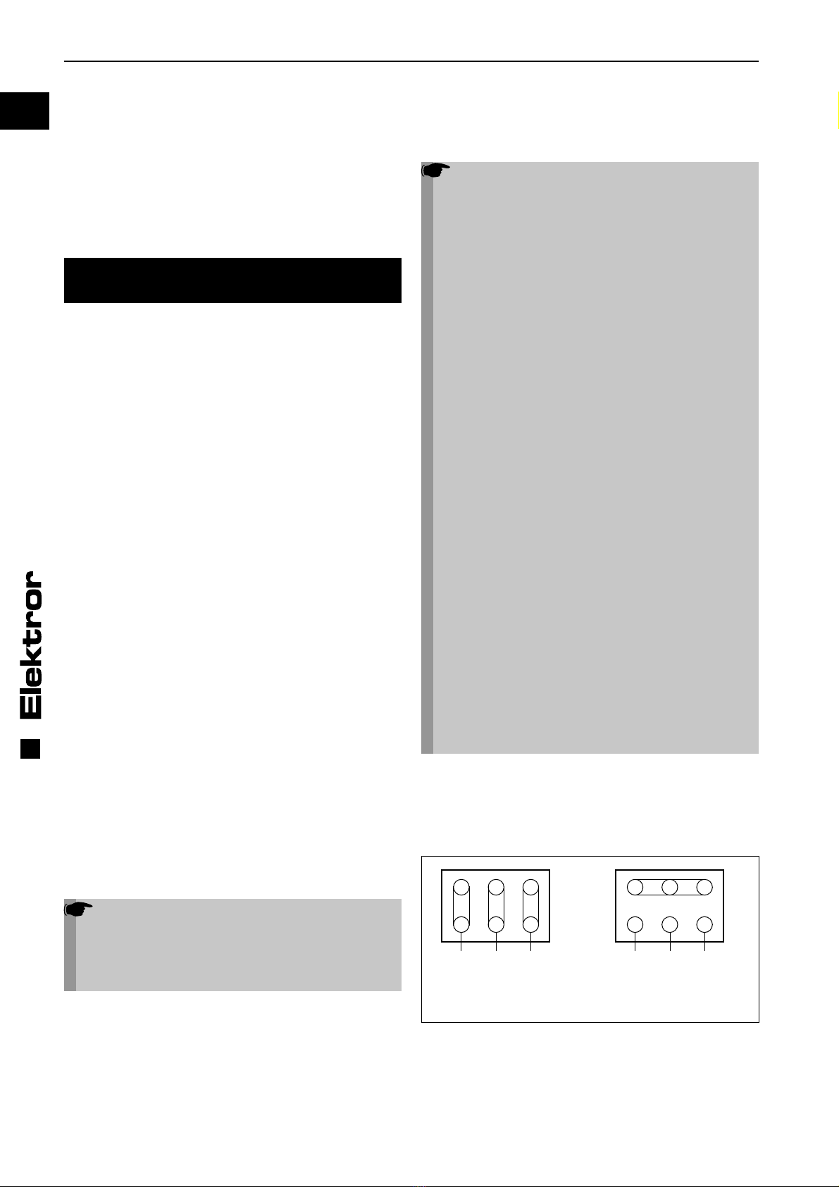
3.1 Aufstellen, Montage
• Ventilator vor Witterung geschützt, horizontal aufstellen.
siehe auch 1.1. Bei Außenaufstellung ist generell ein Wit-
terungsschutz vorzusehen, der die Vorgaben unter 1.1
Bestimmungsgemäße Verwendung erfüllt und den Ventila-
tor vor Wettereinflüssen schützt.
• Auch im anschließenden Betrieb keinen Schwing- oder
Stoßbelastungen aussetzen. Zulässige Schwingungswerte
Ventilator: siehe ISO 14694, BV-3
• Serienventilatoren mit Fuß: Am Einsatzort auf ebenem,
festem, ausreichend tragfähigem Untergrund ohne
Schwingungsübertragung/-belastung fest verschrauben.
• Serien-Ventilatoren ohne Fuß:
Am Einsatzort an feste, ausreichend tragfähige Anbin-
dung, ohne Schwingungsübertragung/-belastung fest ver-
schrauben. Dies ist bei ND-Ventilatoren bei saug- und/oder
druckseitigem Anschluß maximal bis zu folgenden Typen
möglich: Maximal bis D 066 bzw. E 066 und 2D 066.
• Die Aufstellung von Serien-Ventilatoren mit senkrechter
Antriebswelle ist bei ND-Ventilatoren bis zu folgenden
Typen möglich: Maximal bis D 082.
• Offene Ansaug- oder Ausblasstutzen mit Schutzgittern
nach DIN EN ISO 13857 abdecken.
• Für ausreichende Motorbelüftung sorgen. Zulässige Um-
gebungstemperaturen bei:
Serienausführung mit einer Bemessungsspannung
(max. +/-10% Spannungstoleranz) und einer Bemessungs-
frequenz von 50Hz oder 60Hz.
• Umgebungstemperatur -20°C bis +60°C
Sonderspannungen, Mehrspannungsmotoren, FU geeignete
Ausführungen, FUK-Ausführungen, Geräte mit UL-Approba-
tion, Geräte mit Aircontrol:
• Umgebungstemperatur -20°C bis +40°C
Das Belüftungssystem des Antriebsmotors darf nicht durch
die Einbausituation beeinträchtigt werden.
3.2 Elektrischer Anschluß
Hinweis!
Die in diesem Abschnitt beschriebenen Arbei-
ten dürfen nur von einer Elektrofachkraft aus
geführt werden. Anschluß nach dem Schaltbild
im Klemmenkasten und den einschlägigen
örtlichen Bestimmungen vornehmen.
Als Antriebsmotoren kommen Dreh- oder Wechselstrom-
motoren zum Einsatz. In der Gerätekennzeichnung ent-
sprechen die Buchstaben D (Drehstrom 3~) und E (Einpha-
sen- Wechselstrom 1~).
• Der Antriebsmotor ist mit einem Motorschutzschalter abzu-
sichern (gilt nicht für Frequenzumrichter betriebene Geräte).
Für Frequenzumrichter betriebene Geräte ist der vorhande-
ne Temperaturfühler (PTC-Kaltleiterfühler) oder Temperatur-
wächter (Öffnerkontakt) am Umrichter anzuschließen und
auszuwerten.
• Überprüfung, ob die Netzspannung mit der Angabe auf
dem Leistungsschild übereinstimmt.
• Der Schutzleiteranschluß ist im Klemmenkasten vorhanden.
Hinweis!
Bei Betrieb des Antriebsmotors mit Frequenzum-
richter ist zusätzlich folgendes zu Beachten:
• Es dürfen nur Motoren am Frequenzumrichter
betrieben werden die mit der Option „/FU“, für
den „Frequenzumrichterbetrieb geeignet“ auf
dem Leistungsschild gekennzeichnet sind, bzw.
die für „Frequenzumrichterbetrieb geeignet“
bestellt und bestätigt wurden.
• Die Versorgungsspannung des Frequenzum-
richters darf ohne Motorfilter maximal 400 V be-
tragen. Bei längeren Leitungen, höheren Um-
richter-Versorgungsspannungen und/oder Über-
schreitung der Impulsspannungen (max. 1000
Vpk für Antriebsmotoren bis 0,75 kW, max. 1300
Vpk für Antriebsmotoren größer 0,75 kW) an den
Motorklemmen müssen geeignete Maßnahmen an
den Motorklemmen wie z.B. ein Motorfilter zum
Schutz des Motors installiert werden. Bitte wen-
den sie sich diesbezüglich an den Umrichterlie-
feranten. Sofern der Motorfilter im Lieferumfang
enthalten ist, muss dieser zwischen Umrichter
und Motor installiert werden. Bitte sorgen sie für
ausreichend Platzreserve im Schaltschrank und
berücksichtigen die Vorgaben zu Installation und
Montage in den Betriebsanleitungen des Frequen-
zumrichter-/Motorfilterherstellers.
• Die maximale Leitungslänge zwischen Motor
und Frequenzumrichter darf 20 m nicht über-
schreiten und muss mit einem geeigneten,
abgeschirmten Kabel, möglichst auf direktem
Weg und ohne weitere Klemm-/Steckverbindun-
gen ausgeführt werden.
• Das Schirmgeflecht im Anschlusskabel muss
durchgängig und beidseitig d.h. am Frequenzum-
richter und am Motor elektrisch niederohmig mit
dem Erdsystem verbunden sein. Auf der Motor-
seite sind hierzu geeignete EMV-Kabelverschrau-
bungen zu verwenden, die den Kabelschirm am
ganzen Umfang niederohmig kontaktieren.
Weitere Informationen zur EMV-gerechten Installation und
Montage sind den Hinweisen in den Betriebs- und Monta-
geanleitungen des Frequenzumrichterlieferanten zu entneh-
men.
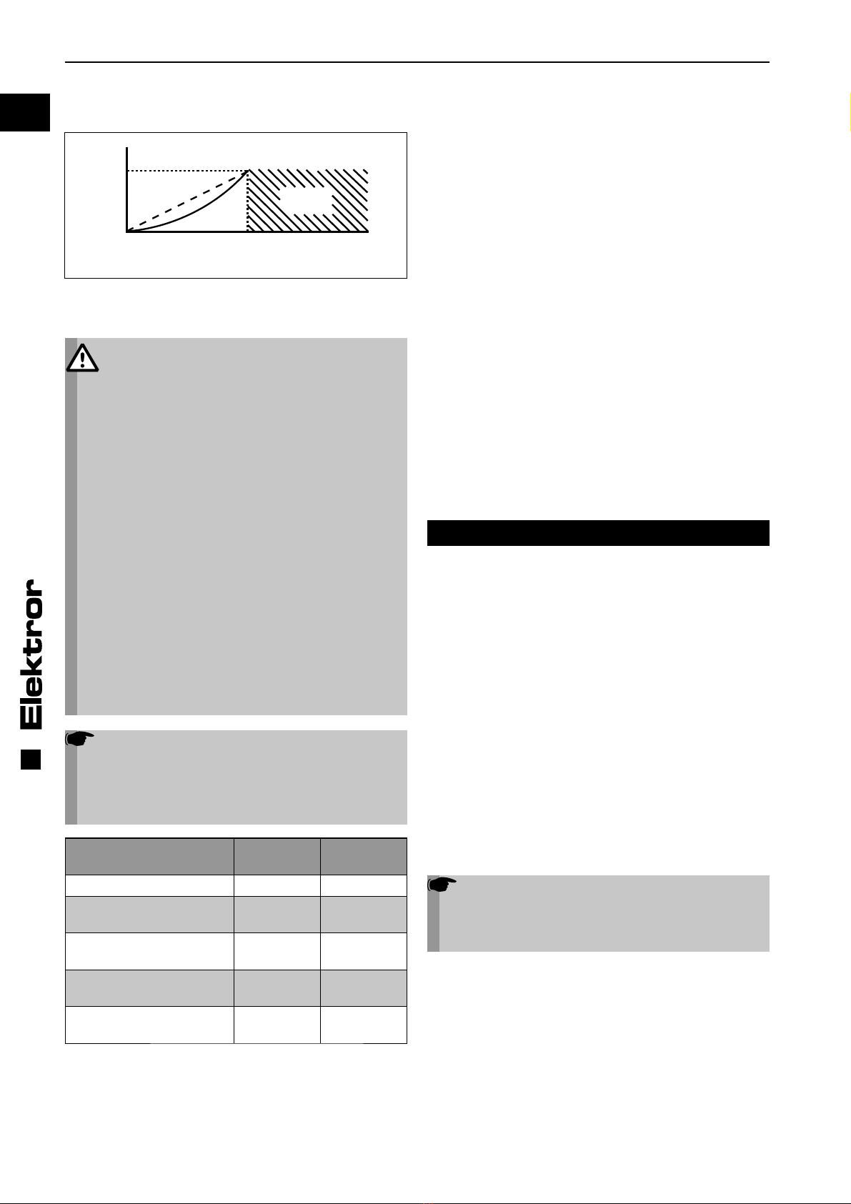
3.2.1 Schaltung für Drehstrom-Ventilatoren
-Schaltung Y-Schaltung
(niedere Spannung) (hohe Spannung)
Drehrichtungsprüfung
Ventilator einschalten. Die Laufrichtung des Laufrades muß
mit dem Richtungspfeil auf dem Gehäuse übereinstimmen.
Bei falscher Drehrichtung sind L1 und L3 zu tauschen.

5
Z2 U2
U1 Z1
L1 N L1 N
Z2 U2
U1 Z1
DE
www.elektror.de Betriebs- und Montageanleitung ND
016303 03.14/09
Stern-Dreieck Anlauf
Motoren über 3,5 kW sind für Stern-Dreieck-Anlauf am Ver-
sorgungsnetz vorgesehen. Für direktes Einschalten (hoher
Kurzschlußstrom im Einschaltaugenblick) bitte die Bedin-
gungen mit Ihrem Energieversorgungsunternehmen klären.
3.2.2 Schaltung für Einphasen-Wechselstrom-Ventilatoren
Rechtslauf Linkslauf
3.3 Sonderverschaltungen und Zusatzklemmen
Für Spannungsumschaltbare Motoren, Polumschaltbare
Motoren, FU Motoren und sonstige Sonderverschaltungen
von Dreh- und Wechselstrommotoren liegen im Klemmen-
kasten der Motoren Anschlusspläne der Lieferung bei. Das
gilt auch für den optionalenThermischen Wicklungsschutz
und die Stillstandsheizung.
3.4 Erklärung zur EMV-Richtlinie (2004/108/EG)
Unsere Ventilatoren sind Komponenten die zum Einbau
durch Fachpersonal in andere Maschinen oder Anlagen be-
stimmt, d.h. nicht für den Endanwender vorgesehen sind.
Die Konformität der Endanlage/Maschine mit der EMV-Richt-
linie muss vom Hersteller der Endanlage/Maschine sicherge-
stellt / bestätigt werden.
Ventilatoren bei Netzbetrieb:
Bei Netzbetrieb an sinusförmiger Wechselspannung erfüllen
die in den Geräten eingebaute Asynchronmotoren mit Kä-
figläufer die Anforderungen an die EG-Richtlinie „Elektroma-
gnetische Verträglichkeit“ 2004/108/EG unter Berücksichti-
gung der Normen EN 61000-6-4 (Störaussendung Industrie)
EN 61000-6-3 (Störaussendung Wohnbereich).
Ventilatoren bei Frequenzumrichterbetrieb (FU):
Vor der Inbetriebnahme und beim Betrieb der Geräte am
Frequenzumrichter (sofern dafür geeignet) müssen zur
Erreichung der Anforderungen der EG-Richtlinie „Elektro-
magnetische Verträglichkeit“ 2004/108/EG unbedingt die
EMV-Hinweise des Frequenzumrichterherstellers und die
Angaben in der Elektror- Betriebs- und Montageanleitung
beachtet werden.
Wird das Gerät zusammen mit einem Elektror-Schaltschrank-
Frequenzumrichterpaket ausgeliefert, ist unter Beachtung
der oben genannten EMV-Hinweise die Einhaltung der EN
61800-3 Kategorie C2 (Industriebereich) möglich.
Warnung:
In einer Wohnumgebung kann dieses Produkt
hochfrequente Störungen verursachen, die Ent-
störmaßnahmen erforderlich machen können.
Ventilatoren mit aufgebautem Frequenzumrichter (FUK):
Geräte mit direkt aufgebautem Frequenzumrichter erfüllen
unter Berücksichtigung der EMV-Hinweise des Frequenz-
umrichterherstellers und den Angaben in der Elektror- Be-
triebs- und Montageanleitung die Anforderungen an die EG-
Richtlinie „Elektromagnetische Verträglichkeit“ 2004/108/EG
unter Berücksichtigung der Norm EN 61800-3 Kategorie C2
(Industriebereich).
Warnung:
In einer Wohnumgebung kann dieses Produkt
hochfrequente Störungen verursachen, die Ent-
störmaßnahmen erforderlich machen können.
Vor der Inbetriebnahme ist in jedem Fall ein CE-Konformi-
tätsbewertungsverfahren mit den zutreffenden Normen und
Richtlinien durchzuführen.
4 ANGABEN ZU BETRIEB UND
VERWENDUNG
4.1 Grundlegende Hinweise
Bitte beachten Sie die unter 1.1 beschriebenen Hinweise zur
bestimmungsgemäßen Verwendung, sowie die unter 1.2 bis
1.11 beschriebenen Sicherheitshinweise.
Wenn im Betrieb der Bemessungsstrom des Antriebsmotors
überschritten wird, prüfen Sie, ob Netzspannung und -fre-
quenz mit den Daten des Gerätes übereinstimmen.
Nach Schutzabschaltungen wie z.B. Auslösen des Motor-
schutzschalters, Ansprechen des PTC-Auswertegerätes
bei Motoren mit Kalteiterfühler oder Schutzabschaltung des
Frequenzumrichters bei FU-Anwendungen ist ein Neustart
des Gerätes erst nach Identifikation und Beseitigung der Stö-
rungsursache zulässig.
Bei Ventilatoren, die nicht über die ganze Kennlinie einsetz-
bar sind, kann bei zu geringem Anlagenwiderstand der Motor
überlastet werden (zu hohe Stromaufnahme). Drosseln Sie
den Volumenstrom in diesem Fall durch eine auf der Druck-
oder Saugseite eingebaute Drosselklappe.
Der Ventilator darf keinen Schwing- oder Stoßbelastungen
ausgesetzt werden.
4.2 Frequenzumrichterbetrieb
Durch den Einsatz eines Frequenzumrichters ist ein
großer Drehzahlstellbereich möglich, wobei nur eine geringe
belastungsabhängige Drehzahldifferenz zwischen Leerlauf
und max. Belastung der Ventilatoren auftritt.
Für den störungsfreien Betrieb der Ventilatoren und
ist es wichtig, daß der Umrichter folgende Forderungen
erfüllt:
• Umrichterleistung gleich oder größer Motorleistung *)
• Umrichterstrom gleich oder größer Motorstrom *)
• Ausgangsspannung des Umrichters gleich der
Motorbemessungsspannung
• Die Pulsfrequenz des Umrichters sollte 8 kHz betragen,
da eine geringere Pulsfrequenz starke Motorgeräusche
erzeugt
• Der Umrichter muss einen Anschluß für Temperatur-
fühler (PTC-Kaltleiterfühler) oder einen Temperaturwäch-
ter (Öffnerkontakt) haben
*) Werte siehe Leistungsschild
Der Motor kann in Dreieck- oder Sternschaltung, je nach
Eingangsspannung des Umrichters betrieben werden.
6
UB
0fB
verbotener
Bereich
DE
Betriebs- und Montageanleitung ND www.elektror.de
016303 03.14/09
Unbedingt ist folgende U/f-Zuordnung am Umrichter
einzustellen.
fBund UB= siehe Leistungsschild
Bei Nichtbeachtung steigt der Motorstrom überproportional
an und der Antriebsmotor kommt nicht auf Bemessungsdreh-
zahl.
Warnung!
Zur Vermeidung von Personenschäden bzw. einer
Zerstörung des Ventilators und einer Motorüber-
lastung darf keinesfalls am Umrichter eine hö-
here Frequenz (Drehzahl) eingestellt werden, als
die Frequenz (fB), welche auf dem Leistungsschild
angegeben ist, da entweder der Motor überlastet
wird, oder durch die überhöhte Drehzahl der Ven-
tilator zerstört werden kann. Die Temperaturfüh-
ler sind zum Schutz des Antriebsmotors an den
entsprechenden Umrichtereingängen anzuschlie-
ßen. Einphasen-Wechselstrommotoren sind für
Umrichterbetrieb nicht geeignet.
Die vom Lieferanten des Frequenzumrichters in
den jeweiligen Bedienungs- oder Applikations-
handbüchern beschriebenen Installations- und
Sicherheitshinweise sind unbedingt einzuhalten,
um einen sicheren und störungsfreien Betrieb zu
gewährleisten.
Zusätzlich ist bei FUK-Geräten zu beachten, daß
es bei besonderen Umgebungsbedingungen zu
einer starken Verschmutzung der Kühlrippen
kommen kann. Ist die Kühlleistung an den Kühl-
rippen nicht ausreichend, schaltet sich der Fre-
quenzumrichter ab. Eine regelmäßige Reinigung
ist für Geräte in diesen Umgebungen erforderlich.
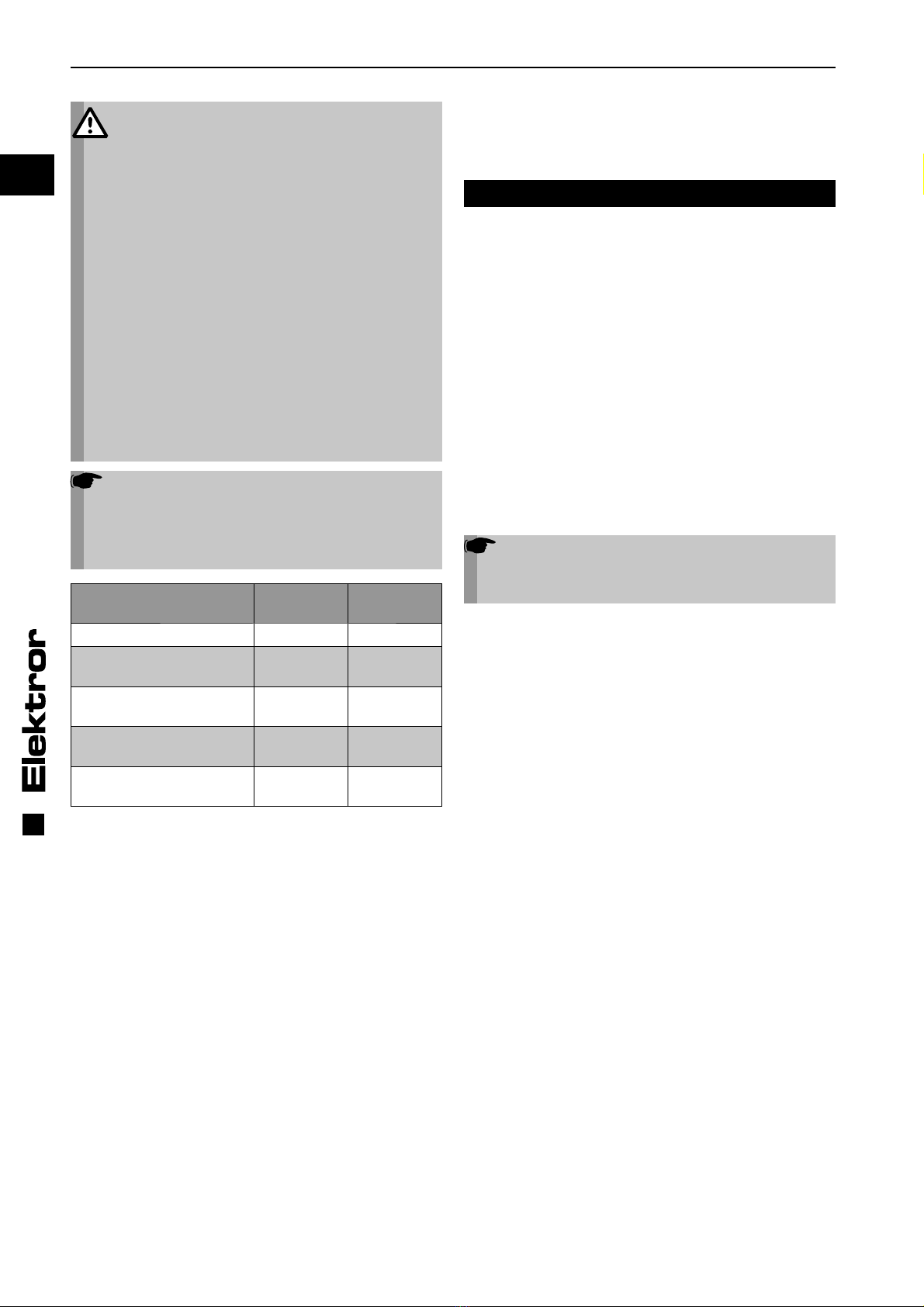
Hinweis!
Zur Vermeidung hoher Bauteilbelastungen und
Störungen im Umrichterbetrieb gelten bei Hoch- /
Ablauf sowie bei Drehzahländerung für die jewei-
lige Geräte-Motorleistungsklasse (siehe Typen-
schild) nachfolgende Zeiten:
Geräte-Motorleistung Hochlaufzeit
[s]
Ablaufzeit
[s]
Motorleistung < 0,25 kW 5 10
0,25 kW < Motorleistung
<= 3,0 kW 10 20
3,1 kW < Motorleistung
<= 7,5 kW 20 40
7,6 kW < Motorleistung
<= 11,0 kW 30 60
11,1 kW < Motorleistung
<= 30,0 kW 30 100
Innerhalb der Hoch- und Ablaufzeiten muß ein gleichmäßiger
Hoch-und Ablauf gewährleistet sein.
Im laufenden Betrieb dürfen keine Drehzahländerungen auf-
treten, die die Drehzahländerung beim Hoch- und Ablauf
überschreiten.
Schutz durch Fehlerstrom-Schutzschalter
(FI-Schutzschalter):
Die aktuellen IGBT-Frequenzumrichter verursachen prin-
zipbedingt Ableitströme >=3,5 mA. Diese Ableitströme kön-
nen zu Fehlauslösungen in Anlagen führen, die über einen
30 mA-FI-Schutzschalter abgesichert sind.
Im Fehlerfall können Fehlerströme auch als Gleichstrom
über den Schutzleiter abfließen. Sofern ein Schutz durch
FI-Schutzschalter auf der Versorgungsseite erforderlich ist,
muss unbedingt ein allstromsensitiver (Typ B) FI-Schutz-
schalter verwendet werden. Der Einsatz eines falschen FI-
Schutzschalters anders als Typ B kann im Fehlerfall zu Tod
oder schweren Verletzungen führen. Zur Erfüllung der Norm
EN 61800-5-1 muss die Schutzleiterverbindung doppelt,
über getrennte Klemmen ausgeführt oder ein Schutzleiter-
querschnitt mit mindestens 10 mm² Cu ausgeführt werden.
Betrieb und Anschluss an öffentlichen Versorgungs-
netzen:
Siehe 3.4
4.3 Hydraulikmotorbetrieb
Beim Betrieb mit Hydraulikmotoren sind die unter 4.2 ange-
gebenen Hoch- und Ablaufzeiten sowie die Drehzahlände-
rungen zu beachten. Um ein ruckfreies Auslaufen zu gewähr-
leisten, sind Hydraulikmotoren mit Freilauf zu verwenden.
5 ANGABEN ZUR INSTANDHALTUNG
Verschleißteile unterliegen den empfohlenen Instandhal-
tungsintervallen (siehe 5.1 bis 5.4). Die Lebensdauer von
Verschleißteilen (Kugellager und Filter) ist abhängig von den
Betriebsstunden, der Belastung und sonstigen Einflüssen
wie Temperatur usw.
Maßnahmen zur, sowie Wartung und Instandhaltung selbst,
dürfen nur von ausreichend sach- und fachkundigen, regel-
mäßig geschulten Personen ausgeführt werden. Dabei ist
zusätzlich zur Betriebsanleitung des jeweiligen Gerätes so-
wie den Vorschriften und Empfehlungen der gesamten Anla-
ge folgendes zu beachten:
Inspektions- und Wartungsintervalle:
In Abhängigkeit von Betriebsstunden, Belastungen und Ein-
satzbedingungen hat der Betreiber das Reinigungs-, Inspek-
tions- und Wartungsintervall selbst festzulegen.
Sofortige Inspektion und Wartung:
Bei Auftreten von Vibrationen und Schwingungen, vermin-
derter Luftleistung.
Hinweis!
Reparaturen dürfen nur vom Hersteller ausge-
führt werden. Bei Reparaturen; Veränderungen
oder Austausch von Bauteilen durch Dritte über-
nehmen wir keine Haftung.
5.1 Kugellager
Der Ventilator ist mit geschlossenen Rillenkugellagern aus-
gestattet, die nicht nachgeschmiert werden müssen und
bei waagrechter Antriebswelle eine Mindestlaufdauer von
22.000 Stunden haben. Bei senkrechter Einbaulage halbiert
sich dieser Wert.
Vor Ablauf der Lebensdauer, mind. 22.000 Stunden, wird
ein Austausch der Kugellager empfohlen. Bei Dauerbetrieb/
Dauereinsatz von 24 Stunden täglich sollte die Betriebszeit
von 30 Monaten nicht überschritten werden.
7
DE
www.elektror.de Betriebs- und Montageanleitung ND
016303 03.14/09
5.2 Abdichtungen und Radial-Wellendichtringe
Abdichtende Bestandteile und Radialwellendichtringe sind
aus Sicherheitsgründen mindestens bei jeder Wartung zu
erneuern, bei der abdichtende Elemente geöffnet, entfernt
oder auf andere Weise verändert wurden.
5.3 Feinfilter
Der Verschmutzungsgrad der Filtermatten ist in regelmä-
ßigen Abständen in Abhängigkeit von den Einsatz-/Umge-
bungsbedingungen zu überprüfen. D.h. die Durchlässigkeit
der Filter ist vom Betreiber zu gewährleisten.
5.4 Reinigung
Durch rotierende Teile besteht im Inneren des Gerätes im
Betrieb hohes Verletzungsrisiko. Setzen Sie das Gerät vor
dem Öffnen, Hineinfassen oder Einführen von Werkzeugen
in jedem Falle ausser Betrieb und warten Sie den Stillstand
aller bewegten Teile ab. Sichern Sie das Gerät während des
gesamten Zeitraumes zuverlässig gegen Wiederanlauf ab.
Stellen Sie ebenfalls sicher, dass keine Gefährdungssitu-
ation in Folge eines Wiederanlaufes nach einem Stillstand
entsteht, z.B. in Folge einer Energie-Unterbrechung oder
Blockade.
Reinigung oder Wartung dürfen zu keinen Beschädigungen
oder Veränderungen am Gerät und seinen Bestandteilen
führen, die Sicherheits- oder Gesundheitsschutz beeinträch-
tigen, und dürfen z.B. den Wuchtzustand des Laufrades nicht
verschlechtern.
Stellen Sie vor Wiederinbetriebnahme des Ventilators sicher,
das alle Werkzeuge oder sonstigen Fremdkörper aus dem
Geräteinneren entfernt wurden und alle Deckel und Schutz-
gitter wieder ordnungsgemäß montiert sind.
6 SICHERHEITSRELEVANTE
INFORMATIONEN ÜBER
AUSSERBETRIEBNAHME UND ABBAU
Das Trennen aller elektrischen Verbindungen und aller wei-
teren elektrotechnischen Maßnahmen in Verbindung mit der
Ausserbetriebnahme darf nur von einer Elektrofachkraft aus-
führt werden.
Der Abbau ist erst zulässig, wenn alle rotierenden Teile den
Stillstand erreicht haben und ein Wiederanlauf nicht mehr
möglich ist.
Zum Abbau und Abtransport müssen die Vorgaben aus 2.1
Transport und Handhabung eingehalten werden.
Die Entsorgung muß fachgerecht durchgeführt werden.
7 HAFTUNG UND HAFTUNGSAUS-
SCHLUSS
Die Verantwortung für die bestimmungsgemäße Verwen-
dung des Gerätes trägt der Betreiber.
Die Fa. Elektror lehnt jede Haftung für nicht bestimmungsge-
mäßen Gebrauch ihrer Geräte und Komponenten ab.
Dies gilt insbesondere auch für besondere Verwendungen
und Einsatzbedingungen, die nicht ausdrücklich mit der Fa.
Elektror abgestimmt wurden.
Elektror lehnt zudem jede Haftung ab für Veränderungen
oder Umbauten am gelieferten Gerät oder Zubehör.
Ebenso haftet die Fa. Elektror nicht für unsachgemäße, ver-
spätete, nicht durchgeführte oder nicht von Elektror-Fach-
personal ausgeführte Wartungsarbeiten und Reparaturen
und deren möglichen Folgen.

8
DE
Betriebs- und Montageanleitung ND www.elektror.de
016303 03.14/09
Hiermit erklärt die
Elektror airsystems gmbh
Hellmuth-Hirth-Strasse 2
D-73760 Ostfildern
als Hersteller, dass das Produkt, auf das sich diese Erklärung bezieht, den unten folgenden grundlegenden Anforderungen der
Richtlinie Maschinen (2006/42/EG) entspricht.
Beschreibung der unvollständigen Maschine:
Niederdruck-Ventilator D 03 M, E 03, D 04 M, E 04, D 045 M, E 045, D 05 M, E 05, D 052 M, E 052, D 060, E 060, D 064, E 064,
D 066, E 066, D 07, D 072, D 08, D 082, D 09, D 092, 2D 04, 2D 045, 2D 05, 2D 052, 2D 060, 2D 064, 2D 066, 2D 07, 2D 08
Serien-Nummer und Baujahr sind dem Leistungsschild und dem zugehörenden Lieferschein zu entnehmen.
Beschreibung der grundlegenden Anforderungen der Richtlinie Maschinen (2006/42/EG), denen die unvollständige
Maschine entspricht:
Richtlinie Maschinen (2006/42/EG): Anhang I, Artikel 1.1.2, 1.1.3, 1.1.5, 1.3.2, 1.3.3, 1.3.4, 1.3.7, 1.5.1, 1.6.1, 1.7.1, 1.7.3
Richtlinie über die elektromagnetische Verträglichkeit (2004/108/EG)
Richtlinie zur umweltgerechten Gestaltung energieverbrauchsrelevanter Produkte (2009/125/EG)
Die aufgeführte unvollständige Maschine erfüllt weiterhin die Schutzziele der Niederspannungsrichtlinie (2006/95/EG) gemäß
Anhang I, Nr. 1.5.1 der Maschinenrichtlinie.
Die Inbetriebnahme der unvollständigen Maschine ist so lange untersagt, bis festgestellt wurde, dass die Maschine, in die die unvoll-
ständige Maschine eingebaut werden soll, den Bestimmungen der Richtlinie Maschinen (2006/42/EG) entspricht.
Die folgenden harmonisierten Normen wurden angewandt:
DIN EN 12100-1 Sicherheit von Maschinen – Grundbegriffe, allgemeine Gestaltungsleitsätze,
Teil 1: Grundsätzliche Terminologie, Methodik
DIN EN 12100-2 Sicherheit von Maschinen – Grundbegriffe, allgemeine Gestaltungsleitsätze,
Teil 2: Technische Leitsätze und Spezifikationen
DIN EN 60034-1 Drehende elektrische Maschinen, Teil 1: Bemessung und Betriebsverhalten
DIN EN 60034-5 Drehende elektrische Maschinen, Teil 5: Schutzarten aufgrund der Gesamtkonstruktion von
drehenden elektrischen Maschinen (IP-Code) – Einteilung
DIN EN 60204-1 Sicherheit von Maschinen – Elektrische Ausrüstung von Maschinen,
Teil 1: Allgemeine Anforderungen
DIN EN 60664-1 Isolationskoordination für elektrische Betriebsmittel in Niederspannungsanlagen,
Teil 1: Grundsätze, Anforderungen und Prüfungen
Die Elektror airsystems gmbh als Hersteller verpflichtet sich, die speziellen Unterlagen zu dieser unvollständigen Maschine einzel-
staatlichen Stellen auf Verlangen elektronisch oder in Papier-Form zu übermitteln. Die zu dieser unvollständigen Maschine gehören-
den speziellen technischen Unterlagen nach Anhang VII Teil B wurden erstellt.
Dokumentationsbevollmächtigter ist Herr Steffen Gagg, Tel. +49(0)711/31973-124.
Kreher (Geschäftsführer)
Ostfildern, 02.05.2013
8 EINBAUERKLÄRUNG NACH ANHANG II 1 B
9
DE
www.elektror.de Betriebs- und Montageanleitung ND
016303 03.14/09

10
Typ Nr.
kW cos kW cos
Hz min-1 min-1 Hz
Mot. EN 60034-1 IP W-Kl.F
V V
A A
D-73760 Ostfildern
Germany
EN
Operating and assembly instructions ND www.elektror.com
016303 03.14/09
CONTENT
1 MACHINE SPECIFICATIONS
2 INFORMATION ON TRANSPORTATION,
HANDLING AND STORAGE OF THE MACHINE
3 INFORMATION ON COMMISSIONING THE MACHINE
4 INSTRUCTIONS FOR OPERATION AND USE
5 INSTRUCTIONS FOR MAINTENANCE
6 SAFETY RELATED INFORMATION ON
TAKING OUT OF OPERATION AND REMOVAL
7 LIABILITY AND EXCLUSION OF LIABILITY
8 DECLARATION OF INSTALLATION CONFORMITY
PURSUANT TO ANNEX II 1 B
9 BROKEN VIEW DRAWING
10 GENERAL SPARE PARTS LIST
11 TECHNICAL SPECIFICATIONS
12 INDICATIONS ACCORDING TO ERP IMPLEMENTING
REGULATION 327/2011
These Operating and Assembly Instructions should be avail-
able to operating personnel at all times. Read these Operat-
ing and Assembly Instructions carefully before installing and
putting the blower into service.
Subject to change without prior notice. If in any doubt, the
manufacturer should be consulted. This document is protect-
ed by copyright. It must not be disclosed to third parties with-
out our express written consent. Any form of duplication or
recording and storage in electronic equipment is forbidden.
1 MACHINE SPECIFICATIONS
Please refer to the cover sheet for our address.
For details of the scope of these Operating and Assembly
Instructions, please refer to the Declaration of Installation
Conformity pursuant to Annex II 1 B.
The technical specifications on page 18 ff. apply to the stand-
ard version. Your blower’s specifications may differ from
these specifications (refer to rating plate). If this is the case,
please refer to the enclosed, additionally applicable docu-
ments or your own applicable Operating and Assembly In-
structions.
Rating plate
The data on the rating plate is applicable to connection,
maintenance and ordering of spare parts. Also refer to the
rating plate for the serial number of the appliance and its year
of manufacture.
1.1 Designated use
The blowers are exclusively designed for conveying gaseous
media without solids.
Any solid matter or impurities in the medium to be conveyed
must be filtered out before they enter the blower. We recom-
mend a condensed water borehole at the lowest point in the
housing in the event of the formation of condensation.
Use of the blowers for
• aggressive,
• abrasive,
• sticky,
• toxic,
• potentially explosive or
• very moist
media is not permissible.
The maximum temperature of the conveyed medium must not
exceed -20°C to +80°C in the standard version and 180°C in
special versions fitted with a thermal barrier. Solid particles
or contaminants must be removed by a filter unit before en-
tering the blower. The maximum ambient temperature must
not exceed +60° C in the standard version.
The blower is not suitable for open-air installation or switched-
mode operation. The blower is fundamentally designed for
S1 operation (continuous operation). However, a maximum
of 30 switching operations per hour are permitted.
The standard version of the blower is not suitable for use in
explosive atmospheres.
Special versions for applications not mentioned above are
available on request. Remodelling and modification of the
blower are not permitted. In the case of special equipment,
the enclosed supplementary Operating and Assembly In-
structions must be observed and adhered to. The supple-
mentary instructions differ in certain respects from these Op-
erating and Assembly Instructions.
Elektror blowers offer a high level of operational reliability.
As the blowers are high-powered machines, the safety in-
structions must be strictly observed in order to avoid injuries,
damage to objects and to the machine itself.
1.2 Mechanical hazards
The mechanical hazards in Elektror blowers have been mini-
mised in accordance with the current state of the art, as well
as the requirements for safety and health protection. To elimi-
nate any further risk on the part of the operator, we recom-
mend that suitable protective gear be used and worn during
all lifecycle phases of the appliance (please refer to the in-
structions below).
1.3 Hazards arising from reaching in and unexpected
start-up
The rotating parts inside the appliance pose a high risk of
injury during operation. Before opening, reaching in or insert-
ing tools into the appliance, always shut it down and wait
until all moving parts come to a standstill. Make sure the ap-
pliance is reliably protected against restarting while work is
in progress.
Also make sure that no hazardous situation can occur as a
consequence of restarting after shutdown, e.g. as a result of
a power cut or blockage.
1.4 Weight and stability
Beware of falling hazards during transportation and installa-
tion in particular. Refer to 2.1 – Transportation and handling,
as well as 3.1 – Installation and assembly.
1.5 Suction effect
The blowers produce a powerful suction effect.
Warning!
Objects, items of clothing and also hair can be
sucked into the intake port. Risk of injury!
Do not stand near the intake opening during op-
eration. The blower must not under any circum-
stances be operated with the intake port open,
and should, therefore, be covered with a wire
guard in conformity with DIN EN ISO 13857
(danger of injury from impeller!).
11
EN
Operating and assembly instructions NDwww.elektror.com
016303 03.14/09
1.6 Blowing effect
Warning!
The blowing effect is very powerful on the ex-
haust side. Sucked in objects may be ejected at
very high speed (danger of injury).
The blowers are designed for delivery of clean
air only. To reliably prevent the sucking-in of
foreign objects or contaminants, which might be
discharged, these objects have to be removed be-
fore entering into the blower by installing a filter.
Do not reach into the exhaust.
1.7 Temperature
Warning!
The blower housing assumes the temperature of
the conveyed medium during operation. If this
is above +50° C, the blower must be protected
against direct contact by the operator
(risk of burning!).
Warning!
The motor housing heats up during operation. If
the temperature rises above +50 °C, the blower
must be protected by the operating company
against direct contact
(risk of burning!).
1.8 Motor circuit breaker
Before putting the blower into operation, be sure to safeguard
the drive motor with a motor circuit-breaker (this does not
apply to frequency-converter-operated appliances). Where
appliances are frequency-converter-operated, the existing
temperature sensor (PTC resistor sensor) or temperature
switch (normally closed contact) must be connected to the
converter and evaluated.
1.9 Noise emission
The noise generated by a blower is not constant throughout
the performance range. For details of noise emission levels,
please refer to the table on pages 18, 19 and 20.
In some cases, sound insulation may be necessary (it is rec-
ommended that emission levels be measured by the opera-
tor). Sound insulation must be provided by the operator to
avoid exceeding the statutory maximum levels at the work-
place and in the immediate vicinity of the blower.
No sound insulation of any kind whatsoever should cause
the ambient temperature to exceed +40°C at the drive motor
(this is not permissible).
1.10 Electrical hazards
Before carrying out electrical work, the appliance must al-
ways be switched off and protected against accidental re-
starting. Check that no voltage is present.
1.11 Speeds
Warning!
The maximum speed stamped on the motor rating
plate must never be exceeded in order to prevent
personal injury. The blower is at risk of mechani-
cal damage if the speed is exceeded.
This can cause serious injury or death!
Each component on the blower has unique natural frequen-
cies. These can be induced by certain blower speeds, which
may result in resonance mode.
The blowers are designed in such a way that resonance does
not generally occur at a constant operating speed.
This may be induced in certain circumstances when the
speed is changed if the blower is operated on a frequency
converter. These circumstances are also influenced by the
customer’s individual installation situation or ventilation con-
nection.
These natural frequencies must be excluded by parametris-
ing the frequency converter accordingly should they be pre-
sent within the speed range of the blower.
2 INFORMATION ON TRANSPORT,
HANDLNG AND STORAGE OF THE
MACHINE
2.1 Transportation and handling
• Prior to installation and putting into service, check all parts
for transit damage. A damaged blower is a potential safety
hazard and, therefore, should not be put into service.
• Do not store the blower unprotected in the open
(protect against moisture).
• Attach hoist securely. Only use hoists and load
suspension devices with sufficient load-carrying capacity.
Secure the route of transportation.
Note!
The eye bolt on the motor must not be used to lift
the entire blower. This is used if the motor needs
to be (dis-)assembled.
2.2 Storage
• Ensure that the air intake connection and pressure connec-
tion are closed.
• Store the blower
-> in its original packaging if possible
-> in a closed room
-> in a dry, dust-free and vibration-free area.
• Storage temperature range from -20°C to +60°C
• After a storage period of 6 months, the blower bearings
and/or motor bearings should be checked before they are
mounted in the blower.

12 W2 U2 V2
U1 V1 W1
W2 U2 V2
U1 V1 W1
(L3) (L1) (L3) (L1)
L1 L2 L3 L1 L2 L3
EN
Operating and assembly instructions ND www.elektror.com
016303 03.14/09
3 INFORMATION ON COMMISSIONING
THE MACHINE
3.1 Installation and assembly
• Protect the blower from the weather and install it in a
horizontal position, see also 1.1. For outdoor use, protec-
tion from the weather must generally be provided that fulfils
the requirements listed in 1.1 Intended Use and protects
the blower from the influences of the weather.
• Avoid vibrational and impact loads during operation.
Permissible vibrational load on blower:
refer to ISO 14694, BV-3.
• Standard blowers with base:
Bolt securely to a level
and firm surface at the place of use, making sure that the
surface has adequate load-bearing capacity and avoiding
vibration transmission or vibrational load.
• Standard blowers without base:
Bolt securely to a firm surface at the place of use, making
sure the surface has adequate load-bearing capacity and
avoiding vibration transmission or vibrational load. This
type of installation can be used for ND blowers with an
intake and/or a discharge side connection up to type:
D 066 or E 066 and 2D 066.
• Installation of standard blowers with a vertical drive shaft is
possible with ND blowers up to the following models:
maximum to D 082.
• Cover the open intake and/or a discharge connection with
wire guards compliant with DIN EN ISO 13857.
• Ensure adequate motor ventilation. Permissible ambient
temperatures:
Standard version with rated voltage (max. +/-10% voltage
tolerance) and a design frequency of 50Hz or 60Hz.
• Ambient temperature -20°C to +60°C
Special voltages, multi-voltage motors, FU compatible
versions, FUK versions, appliances with UL certification,
appliances with Aircontrol:
• Ambient temperature -20°C to +40°C
The performance of the drive motor’s ventilation system
must not be impaired by the installation situation
3.2 Electrical connection
Note!
The work described in this section may only be
performed by a qualified electrician. Connect the
appliance to the power supply in the terminal box
as per the wiring diagram and observing the ap-
plicable local regulations.
Three-phase or a.c. motors can be used as drive motors.
In the appliance designation, the letter D stands for three-
phase a.c. and the letter E for single-phase a.c.
• The drive motor has to be safeguarded by a motor circuit
breaker (this does not apply to frequency-converter-oper-
ated appliances). Where appliances are frequency-
converter-operated, the existing temperature sensor
(PTC resistor sensor) or temperature switch (normally
closed contact) must be connected to the converter and
evaluated.
• Check to see if the mains voltage matches the voltage
specified on the rating plate.
• The safety earth terminal can be found in the terminal box.
Note!
For operation of the drive motor with a frequency
converter, the following points should also be
noted:
• Motors may only be operated on a frequency
converter if they have “/FU” (which denotes
“frequency converter compatible”) marked on
the rating plate, or if they have been ordered as
“frequency converter compatible” motors and
confirmed.
• The frequency converter supply voltage must
only be a maximum of 400 V without the motor
filter. Appropriate measures, such as a motor
filter to protect the motor, must be installed on
the motor terminals with longer cables, higher
frequency converter supply voltages and/or if
the pulse voltages are exceeded (max. 1000 Vpk
for drive motors up to 0.75 kW, maximum 1300
Vpk for drive motors larger than 0.75 kW). Please
contact the converter supplier in this case. If a
motor filter is included in the delivery, this must
be installed between the converter and the motor.
Please ensure that there is sufficient space in the
switch cabinet and take into account the installa-
tion and assembly requirements in the operating
instructions of the frequency converter/motor
filter manufacturer.
• The wire running between the motor and the
frequency converter must not exceed a length of
20 m, configured as a suitable, shielded cable and
laid by as direct a route as possible, without any
additional plug/clamp connections.
• The braided screen in the connecting cable
must cover the full length of the cable on both
sides, i.e. be connected to the grounding system
at the frequency converter and to the motor using
a low electrical resistance. For this purpose, suit-
able EMC cable couplings must be used on the
motor side. They must contact the cable shield
around its full circumference and have a low
resistance.
For further information about EMC compliant installation and
assembly, refer to the operating and assembly instructions
issued by the frequency converter manufacturer.
3.2.1 Configuration for three-phase a.c. blowers
circuit Y circuit
(low voltage) (high voltage)
Checking the direction of rotation
Switch on the blower. The running direction of the impeller
should correspond to the direction arrow on the housing. If
the impeller rotates in the wrong direction, then interchange
L1 and L3.
Star-delta start-up
Motors with ratings of above 3.5 kW are suitable for star-delta
start-up on the mains supply. For direct on-line starting (high
short circuit current at the instant the motor is energised),
please contact your local utility for details of conditions.

13
Z2 U2
U1 Z1
L1 N L1 N
Z2 U2
U1 Z1
U
B
0fB
Prohibited
range
EN
Operating and assembly instructions NDwww.elektror.com
016303 03.14/09
3.2.3 Configuration for single-phase a.c. blowers
Clockwise rotation Anti-clockwise rotation
3.3 Special configurations and additional clamps
Terminal diagrams can be found in the motor terminal box for
voltage interchangeable motors, pole-changeable motors,
FU motors and other special configurations of three-phase
a.c. and a.c. motors. This also applies to the optional thermal
winding protection and the space heater.
3.4 Declaration concerning the EMC Directive
(2004/108/EC)
Our blowers are components that are designed to be in-
stalled in other machines or systems by qualified personnel,
i.e. not intended for consumers. The manufacturer of the
final system/machine must guarantee/confirm that the final
system/machine complies with the EMC Directive.
Blowers with mains operation:
With mains operation to a sinusoidal AC voltage, the asyn-
chronous motors with a squirrel-cage rotor that are built into
the devices meet the requirements of the EC “Electromag-
netic Compatibility” Directive 2004/108/EC, taking into ac-
count the standards EN 61000-6-4 (Emitted interference in
industrial environments) and EN 61000-6-3 (Emitted interfer-
ence in residential environments).
Blowers with frequency converter operation (FC):
Prior to the start-up and during operation of the device on a
frequency converter (provided that this is suitable) it is es-
sential that the EMC instructions from the frequency convert-
er manufacturer and the information in the Elektror operating
and assembly instructions are observed in order to meet the
requirements of the EC “Electromagnetic Compatibility” Di-
rective 2004/108/EC.
If the device is delivered together with an Elektror switch cab-
inet frequency converter package, it is possible to comply
with the EN61800-3 category C2 (Industrial environments),
taking into consideration the above-mentioned EMC instruc-
tions.
Warning!
This product may cause high-frequency inter-
ference in a residential environment that may
require screening measures.
Blowers with an in-built frequency converter (FUK):
Devices with an in-built frequency converter meet the require-
ments of the EC “Electromagnetic Compatibility” Directive
2004/108/EC under consideration of EN 61800-3 Category
C2 (industrial environment), taking into account the EMC in-
structions from the frequency converter and the information
in the Elektror operating and assembly instructions.
Warning:
This product may cause high-frequency inter-
ference in a residential environment that may
require screening measures.
A CE conformity assessment with the relevant standards and
guidelines must be carried out in all cases before the start-
up.
4 INSTRUCTIONS FOR OPERATION
AND USE
4.1 Basic information
Please observe the notes on designated use in section 1.1,
as well as the safety guidelines in sections 1.2 to 1.10.
If electrical current exceeds the rated current of the drive mo-
tor during operation, check to see if the mains voltage and
frequency match the appliance ratings.
After a protective shutdown, e.g. tripping of the motor circuit-
breaker, activation of the PTC evaluation unit by motors with
a PTC resistor sensor, or after a protective shutdown of the
frequency converter during FU applications, the appliance
must not be restarted until the case of the problem has been
identified and eliminated.
If the blower cannot be operated over the whole range of the
characteristic curve, the motor may overload if the system
resistance is too low (excessive current consumption). The
volumetric air flow should be reduced in this case by means
of a throttle valve fitted on the intake or discharge side.
The blower must not be subjected to vibration or impact
loads.
4.2 Frequency converter operation
A frequency converter is used, allowing a wide range of
speed adjustments. There is only a small, load-related dif-
ference in rpm between idle state and the max. load of the
blowers and the lateral channel blower.
To ensure trouble-free operation of blowers and lateral
channel blowers, it is important that the converter meet
the following requirements:
• Converter output equal to or greater than motor power
output *))
• Converter current equal to or greater than motor current *)
• Converter output voltage equal to rated motor voltage
• The pulse frequency of the converter should be 8 kHz,
because a lower pulse frequency will lead to noisy motor
operation
• The converter should have a connection for a tempera-
ture sensor (PTC resistor sensor) or a temperature switch
(normally-closed contact)
*) Refer to the rating plate for data
The motor can be operated in a delta or star-point configu-
ration, depending on the input voltage of the converter.
The following U/f assignments must be configured at
the converter.
fBand UB= refer to rating plate
If this is ignored, the motor current will increase disproportion-
ately and the drive motor will fail to achieve its rated speed.
14
EN
Operating and assembly instructions ND www.elektror.com
016303 03.14/09
Warning!
To avoid personal damage, destruction of the
blower or motor overload, a higher frequency
(speed) than the frequency (fB) specified on the
rating plate must never be set on the converter
otherwise the motor may be overloaded or the
blower destroyed due to the increased speed. The
temperature sensors are connected to the corre-
sponding converter inputs to protective the drive
motor. Single-phase alternating current motors
are not suitable for converter operation.
It is absolutely essential that you observe the
installation and safety instructions described in
the respective operating or application manuals
provided by the frequency converter supplier to
guarantee a safe and trouble-free operation.
It is also important to note that special ambient
conditions may lead to a high level of contamina-
tion of the cooling fins with the FUK devices. The
frequency converter switches off if the cool-
ing output on the cooling fins is not adequate.
Regular cleaning is required for devices in these
environments.
Note!
The following times apply for the respective
device motor output class (see rating plate) with
run-up/expiry as well as speed changes in order
to to avoid high component loads and faults in
the converter operation:
Device motor output Run-up time
[s]
Expiry time
[s]
Motor output < 0.25 kW 5 10
0.25 kW < Motor output
<=3.0 kW 10 20
3.1 kW < Motor output
<= 7.5 kW 20 40
7,6 kW < Motor output
<= 11.0 kW 30 60
11,1 kW < Motor output
<= 30.0 kW 30 100
A uniform run-up and expiry must be guaranteed within the
run-up and expiry times.
No speed changes must occur during operation that exceed
the speed change during run-up and expiry.
Protection by residual-current-operated circuit breaker
(FI circuit-breaker):
The present IGBT frequency converters produce discharge
currents of >=3.5 mA due to their design principle. These dis-
charge currents can lead to unwanted tripping in systems
protected by a 30 mA-FI circuit-breaker.
If a fault occurs, fault currents can also discharge through the
PE conductor as direct current. If protection is needed on the
supply side by means of an FI circuit-breaker, then an ACDC
sensitive (type B) FI circuit-breaker must be used. Use of an
FI circuit-breaker other than type B can cause death or seri-
ous injury if a fault occurs. To meet the EN 61800-5-1 stand-
ard, the PE conductor must be duplexed and routed through
separate terminals or have a cross-section of at least 10 mm²
Cu.
Operation and connection to public grids:
See 3.4
4.3 Hydraulic Motor Operation
The run-up and expiry times as well as the speed changes
specified in 4.2 should be noted when operating with hydrau-
lic motors. Free-running hydraulic motors should be used to
guarantee a smooth run on.
5 INSTRUCTIONS FOR MAINTENANCE
Wearing parts are subject to the recommended maintenance
intervals (refer to 5.1 to 5.4). The service life of wearing parts
(ball bearings and filters) depends on the operating hours,
the load and other influences, such as temperature, etc.
Maintenance and servicing may only be performed by per-
sons with the necessary expertise and regular training. In ad-
dition to the appliance’s operating instructions and the regu-
lations and recommendations for the system as a whole, the
following points should be observed:
Inspection and maintenance intervals:
The operator must set the cleaning, inspection and mainte-
nance intervals himself according to operating hours, load
and operating conditions.
Immediate inspection and maintenance:
The blower must be inspected immediately if vibrations or
reduced air flow are observed.
Note!
Repairs must be carried out by the manufacturer.
We cannot accept any liability for repairs carried
out by third parties.
5.1 Ball bearings
The blower is equipped with closed grooved ball bearings
that do not have to be relubricated and have a minimum ser-
vice life of 22,000 hours in the case of horizontal drive shafts.
This value halves when they are installed vertically.
We recommend exchanging the ball bearings before the end
of their service life (at least 22,000 hours). A service period of
30 months must not be exceeded if the blower runs continu-
ously for 24 hours a day.
5.2 Seals and radial shaft sealing rings
Sealing elements and shaft sealing rings must, for safety rea-
sons, always be replaced after maintenance work involving
opening, removing or otherwise modifying sealing elements.
5.3 Micro-filters
The degree of clogging of the filter mats should be checked
at regular intervals, depending on the ambient conditions /
conditions of use. i.e. the user is responsible for ensuring
that the filters are permeable.
5.4 Cleaning
There is a high risk of injury on the inside of the device due to
rotating parts during operation. Decommission the device in
all cases and wait until all moving parts have stopped before
opening, reaching in or inserting tools into the device. Secure
the device reliably against it being accidentally restarted dur-
ing the entire period.
Also make sure that no other dangerous situation can arise
when restarting after a standstill, e.g. as a result of a power
failure or blockages.
Cleaning or maintenance must not lead to damage or modi-
fications to the device and its components that would influ-
ence safety or health protection and, for example, impair the
balanced state of the impeller.
When starting up the blower, make sure that all tools or other
foreign objects have been removed from inside the device
and that all covers and protective grilles have been attached
correctly.

15
EN
Operating and assembly instructions NDwww.elektror.com
016303 03.14/09
6 SAFETY RELATED INFORMATION
ON TAKING OUT OF OPERATION AND
REMOVAL
The disconnecting of all electrical connections and all oth-
er electrical engineering work in connection with taking the
blower out of operation must be referred to a qualified electri-
cian.
The blower may only be dismantled after all rotating parts
have come to a standstill and a safeguard has been provided
to prevent restarting.
Dismantling and removal must be performed in accordance
with the guidelines set out in section 2.1, Transportation and
handling. Dispose of in the appropriate manner.
7 LIABILITY AND EXCLUSION OF
LIABILITY
The owner shall bear the responsibility for the correct use of
the device.
Elektror shall not accept any liability for any use of its prod-
ucts and components which is contrary to their intended use.
This shall also apply in particular to use in special applica-
tions and under operating conditions that have not been spe-
cifically agreed with Elektror.
Elektror shall not accept any liability for any modifications or
alterations to the device or accessories supplied.
Likewise, Elektror shall not be liable for improper, delayed,
neglected maintenance. Neither shall it be liable for any
cleaning and repair work not carried out by qualified Elektror
specialists, nor for the possible consequences.
16
EN
Operating and assembly instructions ND www.elektror.com
016303 03.14/09
The manufacturer,
Elektror airsystems gmbh
Hellmuth-Hirth-Strasse 2
D-73760 Ostfildern
hereby declares that the product to which this declaration refers meets the basic requirements of the Machinery Directive
(2006/42/EC) as set forth below.
Description of incomplete machine:
Low pressure blower D 03 M, E 03, D 04 M, E 04, D 045 M, E 045, D 05 M, E 05, D 052 M, E 052, D 060, E 060, D 064, E 064,
D 066, E 066, D 07, D 072, D 08, D 082, D 09, D 092, 2D 04, 2D 045, 2D 05, 2D 052, 2D 060, 2D 064, 2D 066, 2D 07, 2D 08
Serial number and year of manufacture can be found on the rating plate and on the accompanying delivery slip.
Description of the essential requirements of Machinery Directive (2006/42/EC), with which the partially completed
machine complies:
Machinery Directive (2006/42/EC): Annex I, Articles 1.1.2, 1.1.3, 1.1.5, 1.3.2, 1.3.3, 1.3.4, 1.3.7, 1.5.1, 1.6.1, 1.7.1, 1.7.3
Electromagnetic Compatibility Directive (2004/108/EC)
Eco-design Directive for Energy-related Products (2009/125/EC)
The partially completed machine described here continues to fulfil the protective regulations of the Low Voltage Directive
(2006/95/EC) according to Annex I, No. 1.5.1 of the Machinery Directive.
The commissioning of the partially completed machine is not permitted until it has been verified that the machine in which
the partially completed machine is to be installed, complies with the provisions of the Machinery Directive (2006/42/EC).
The following harmonised standards were applied:
DIN EN 12100-1 Safety of machinery - Basic concepts, general principles for design;
Part 1: Basic terminology, methodology
DIN EN 12100-2 Safety of machinery - Basic concepts, general principles for design;
Part 2: Technical principles and specifications
DIN EN 60034-1 Rotating electrical machines; Part 1: Rating and performance
DIN EN 60034-5 Rotating electrical machines; Part 5: Degrees of protection provided by integral design of rotating electrical
machines (IP code) – Introduction
DIN EN 60204-1 Safety of machinery - Electrical equipment of machines;
Part 1: General requirements
DIN EN 60664-1 Insulation co-ordination for equipment within low-voltage systems;
Part 1: Principles, requirements and tests
The manufacturer, Elektror airsystems gmbh, undertakes to make the special documentation on this incomplete machine available,
electronically or in hardcopy, to national authorities on demand. The special technical documentation belonging to this incomplete
machine was prepared in accordance with Annex VII Part B.
Mr Steffen Gagg, tel. +49(0)711/31973-124, was responsible for the documentation.
Kreher (Managing Director)
Ostfildern, 02.05.2013
8 DECLARATION OF INSTALLATION CONFORMITY PURSUANT TO ANNEX II 1 B
17
EN
Operating and assembly instructions NDwww.elektror.com
016303 03.14/09
18
016303 03.14/09
35
262523
24 21 19 20 19 18 17 16 15 14 13 12
10
8
9
34
33
12 34 5 6 7 11 18 19 34 21 20 19 11 18 76
32
30
2524
22
31
23
27162829
11 7 65321
22
4
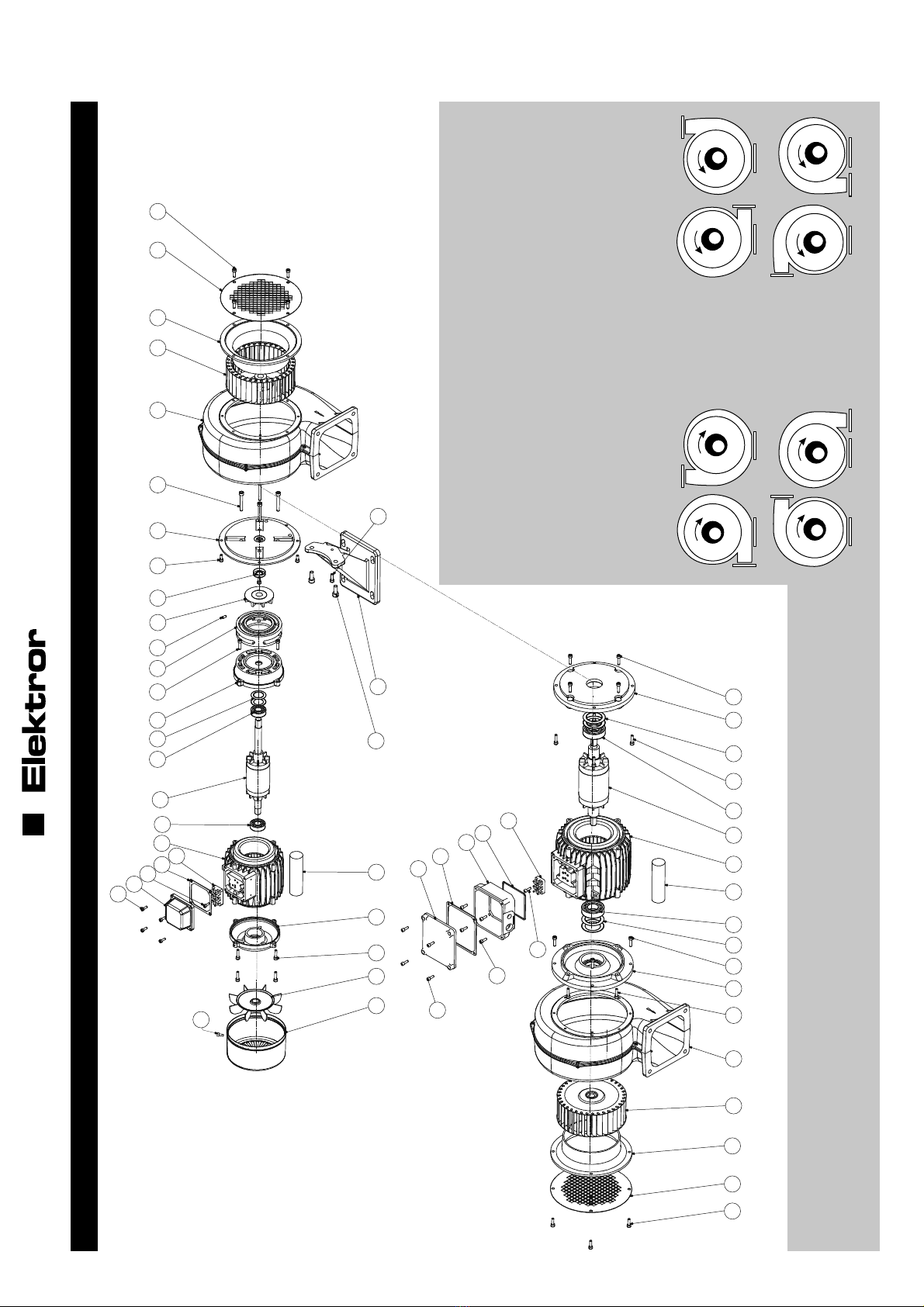
9 EXPLOSIONSZEICHNUNG / BROKEN VIEW DRAWING
Bei der Bestellung bitte angeben:
Geräte-Nr. (Leistungsschild), Geräte-Typ (Leistungsschild)
When ordering please state:
Serial no. (rating plate), Blower type (rating plate) Cr Dr
BrAr
Gl Hl
FlEl
Gehäusestellungen
Die Gehäusestellung des Ventilators ist für die Bestellung einiger Ersatzteile
entscheidend. Ermitteln Sie die Stellung Ihres Ventilators durch Blick auf die
Saugseite. Bestellen Sie Ersatzteile zur Drehrichtung passend.
Rechtsdrehend = Ar bis Dr Linksdrehend = El bis Hl
Housing positions
The position of the blower housing is important for ordering several spare parts.
Determine the position of your blower by looking at the intake end. Order spare
parts which match the direction of rotation.
Clockwise rotation = Ar to Dr Anti-clockwiese rotation = El to Hl
19
016303 03.14/09
10 ALLGEMEINE ERSATZTEILLISTE / GENERAL SPARE PARTS LIST
DE EN
Pos. Benennung Name
19 Rillenkugellager Deep-groove ball bearing
20 Läufer, vollständig Rotor, complete
21 Statorgehäuse Stator housing
22 Klemmbrett, vollständig Terminal board, complete
23 Innensechskantschraube Hex. socket bolt
24 Klemmenkastendichtung Terminal box seal
25 Klemmenkasten Terminal box
26 Innensechskantschraube Hex. socket bolt
27 Lagerschild Endplate
28 Klemmlüfterflügel Ventilator fan blade
29 Lüfterhaube Fan cowling
30 Deckeldichtung Cover seal
31 Innensechskantschraube Hex. socket bolt
32 Klemmenkastendeckel Terminal box cover
33 Innensechskantschraube Hex. socket bolt
34 Betriebskondensator Running capacitor
35 Schraube Screw
DE EN
Pos. Benennung Name
1 Schraube Screw
2 Schutzgitter Wire mesh guard
3 Ansaugring Intake ring
4 Laufrad Impeller
5 Ventilatorgehäuse, vollständig Blower housing, complete
6 Schraube Screw
7 Ventilatorflansch Blower flange
8 Ventilatorfuß Blower base
9 Schraube Screw
10 Schraube Screw
11 Schraube Screw
12 Radialwellendichtung Radial shaft seal
13 Ventilationsflügel Blower blade
14 Gewindestift Grub screw
15 Distanzstück Spacer
16 Schraube Screw
17 Flanschlagerschild Flange endshield
18 Tellerfeder Disc spring
Ihre individuelle Ersatzteilliste können Sie sich im Internet unter www.elektror.de downloaden.
Hierzu benötigen Sie die Seriennummer (siehe Leistungsschild) des Geräts.
You can download your customised spare parts list on the internet at www.elektror.com.
For this purpose, you require the appliance‘s serial number (refer to rating plate).
20
016303 03.14/09
11 TECHNISCHE DATEN / TECHNICAL SPECIFICATIONS
Modell Effizienzklasse Volumenstrom* Gesamtdruck-
differenz*
max. zul.
Ventilator-
drehzahl
Motor-
drehzahl Spannung Frequenz Strom-
aufnahme Motorleistung Betriebs-
kondensator
Gewicht
(ca.)
Schalldruck-
pegel LA*1) Kugellager-
kurzzeichen *2)
Type Efficiency
class Volumetric
flow rate*
Total
pressure
difference*
Max. perm.
blower speed Motor speed Voltage Frequency Power
consumption Motor output Running
capacitor Weight
(approx.)
Min./max.
sound pressure
level *1)
Ball bearing
designation *2)
[m³/min] [Pa] [min-1] [min-1] [V] [Hz] [A] [kW] [μF/V] [kg] [db (A)]
D 03 M
- 3,2 330 3000 2820 208-265/
360-460 50 0,36-0,68/
0,21-0,36 0,03 - 4,2 54 / 63
6202 / 6300
- 3,8 480 3600 3400 208-290/
360-500 60 0,33-0,55/
0,19-0,28 0,05 - 4,2 62 / 68
E 03 - 3,2 330 3000 2880 230 50 0,55 0,03 3/450 3,9 54 / 63 6202 / 6300
- 3,8 480 3600 3350 230 60 0,50 0,05 3/450 3,9 62 / 68
D 04 M
- 5,0 350 3000 2850 208-265/
360-460 50 0,45-0,72/
0,26-0,42 0,07 - 4,5 62 / 67
6202 / 6300
- 6,0 500 3600 3400 208-290/
360-500 60 0,47-0,52/
0,27-0,30 0,12 - 4,5 64 / 72
E 04 - 5,0 350 3000 2850 230 50 0,80 0,07 3/450 4,7 62 / 67 6202 / 6300
- 6,0 500 3600 3400 230 60 0,75 0,12 3/450 4,7 64 / 72
D 045 M
- 8,0 460 3000 2660 208-265
360-460 50 0,48-0,50/
0,28-0,29 0,10 - 5,2 66 / 70
6202 / 6300
- 9,3 650 3600 3070 208-290
360-500 60 0,62-0,61/
0,36-0,35 0,17 - 5,2 70 / 76
E 045 - 8,4 460 3000 2770 230 50 0,82 0,13 3/450 5,4 66 / 70 6202 / 6300
- 9,2 650 3000 2980 230 60 1,17 0,15 3/450 5,4 70 / 76
D 05 M
- 10,0 430 3000 2550 208-265
360-460 50 0,59-0,59/
0,34-0,34 0,13 - 5,0 62 / 72
6202 / 6300
- 11,0 620 3600 3000 208-209/
360-500 60 0,74-0,74/
0,43-0,43 0,22 - 5,0 67 / 74
E 05 - 10,0 430 3000 2550 230 50 1,1 0,14 3/450 5,2 62 / 72 6202 / 6300
- 9,5 620 3600 3300 230 60 0,9 0,14 3/450 5,2 67 / 74
D 052 M
- 15,0 530 3000 2840 208-265
360-460 50 1,25-2,15
0,72-1,24 0,37 - 7,6 62 / 76
6202
- 18,0 760 3600 3350 208-290/
360-500 60 1,73-1,91/
1,00-1,10 0,44 - 7,6 69 / 79
E 052 - 13,5 530 3000 2805 230 50 1,8 0,25 12/450 6,4 62 / 76 6202
- 12,5 760 3600 3365 230 60 2,2 0,30 12/450 6,4 69 / 79
Other manuals for D 03 M
1
This manual suits for next models
28
Table of contents
Languages:
Other Elektror Industrial Equipment manuals


