AGC SMART 51/33 User manual

AGC Stopray SMART –Processing Guide –Version 4.1 –May 2020
STOPRAY SMART
PROCESSING GUIDE
ASIA EDITION
Version 4.1 – May 2020
SMART 51/33 - SMART 30/20 – SMART 32T
This version of the guide replaces and cancels all previous versions.

2
AGC Stopray SMART –Processing Guide –Version 4.1 –May 2020
At each stage of the processing procedure, the personnel responsible for handling the glass
must
have the adequate equipment: safety shoes, safety gloves, safety glasses.
Product shelf life with protection (closed packaging): the glass has to be consumed within 9
months from the delivery in the processor’s facility.
The Stopray SMART range is self-matchable, except for Stopray SMART 32T: these
products can be used annealed or heat treated
as required by the application. Both
annealed and heat treated products have similar reflection and
transmission characteristics.
In case of heat treatment, the procedure and set up of the furnace in
chapter 6 of this manual
must be strictly respected.
Stopray SMART Coatings, when installed in insulating glazing units, have to be assembled
with the coating towards the cavity so in position 2 of the insulating glazing. The glass should
be
assembled in insulating glazing within one week after being heat treated, but advisable
to be assembled earlier.
Stopray SMART 51/33, which can be laminated with coating against PVB, should be
installed in Position 2 so that coating layer is embedded within the laminated glazing and
thereby protected. For more information, refer to Section 9. (*depends on the durability test,
this paragraph might be removed if the test des not passed)
We advise processing and handling this coated glass with care in order to avoid coating
damage.
The personnel responsible for handling must wear clean gloves to ensure that
no fingerprints are
left on the glass. Therefore we strongly recommend that everything
coming into contact with the
coating of the glass during preliminary processes be pre-
validated.
No edge deletion: Tests using different sealants have shown that, under strict conditions and
with a
selection of sealants, prior edge-deletion is no longer required.
Edge deletion is required for laminating SMART 51/33. For more information, refer to
Section 9.
For the various glazing methods (traditional framing, structural glazing) tests for compatibility
and
adherence of the coating with the sealant must be made in each case with the
sealant
manufacturer.
WA R N I N G
Carefully read this manual before processing Stopray Smart products.
PreliminaryImportant Instructions

3
AGC Stopray SMART –Processing Guide –Version 4.1 –May 2020
CONTENTS
1.
PRODUCTS ......................................................................................................................................................................4
I.
RECEPTION AND STORAGE ...............................................................................................................................4
1.
Unloading ...................................................................................................................................................................4
2.
Storage of the packs ........................................................................................................................................5
II.
PROCESSING .......................................................................................................................................................6
1.
Safety & General Information .........................................................................................................................6
2.
Cutting ............................................................................................................................................................7
3.
Edge Processing .........................................................................................................................................7
4.
Edge Deletion .................................................................................................................................................8
5.
Washing .....................................................................................................................................................................8
6.
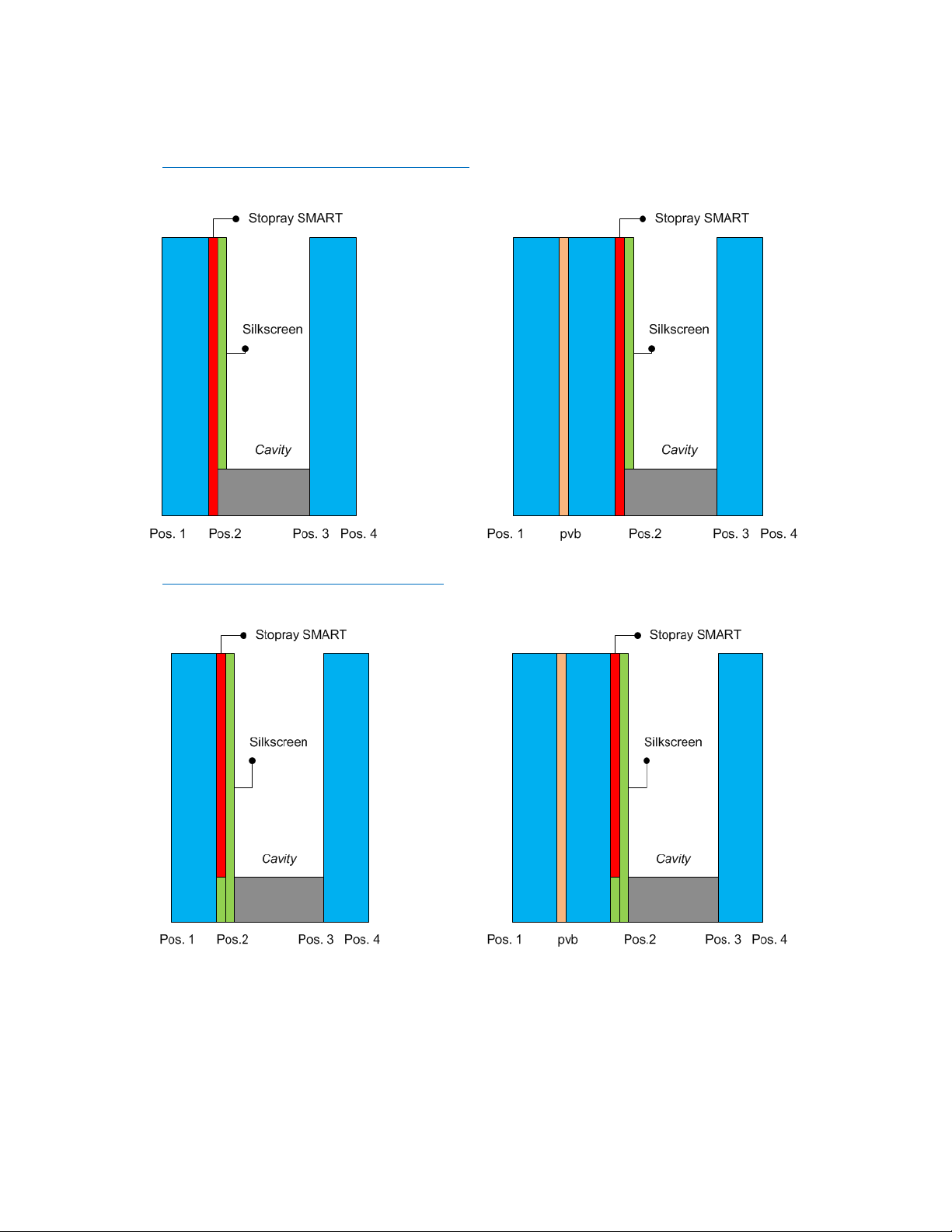
Silk screen printing .........................................................................................................................................9
6.1
Stopray SMART with silkscreen................................................................................................................9
6.2
Stopray SMART laminated with silkscreen .............................................................................................11
7.
Thermal Toughening / Heat strengthening .................................................................................................... 11
7.1
Introduction ............................................................................................................................................. 11
7.2
Generalities............................................................................................................................................. 11
7.3
Recommendations ..................................................................................................................................12
7.4
Settings...................................................................................................................................................13
7.5
Unloading................................................................................................................................................14
7.6
Heat Soak test ........................................................................................................................................14
7.7
Quality control.........................................................................................................................................14
7.8
Packaging ...............................................................................................................................................15
8.
Bending ........................................................................................................................................................15
8.1
Curved annealed glass (on a concave mould)........................................................................................15
8.2
Curved toughened glass (on a concave mould)......................................................................................16
9.
Lamination ................................................................................................................................................17
10.
Assembly in Insulating Glass Unit...................................................................................................................19
11.
Use in Structural glazing...............................................................................................................................20
12.
Identifying the coated surface.......................................................................................................................20
13.
Storage of cut sizes / IGU.............................................................................................................................21
13.1
During processing in the same factory .................................................................................................21
13.2
To send cut size to another factory .......................................................................................................21
13.3
On site ..................................................................................................................................................21
III.
CONFORMITY and GUARANTEE ..........................................................................................................................22
1.
Conformity....................................................................................................................................................22
2.
Warranty...................................................................................................................................................22
3.
Local Standards ........................................................................................................................................22
4.
Disclaimer ....................................................................................................................................................22
IV.
GLAZING INSTRUCTIONS.................................................................................................................................22
V.
CLEANING ON FACADE ........................................................................................................................................22

4
AGC Stopray SMART –Processing Guide –Version 4.1 –May 2020
1.
PRODUCTS
This Processing Guide concerns the Stopray SMART products: Stopray SMART 51/33, Stopray
SMART
30/20 and Stopray SMART 32T.
The Stopray SMART products can be used either annealed (so without heat
treatment) or with heat
treatment (thermal toughening or heat strengthening).
The Stopray SMART products can be used in this configuration:
I.
RECEPTION AND STORAGE
1.
Unloading
The packs of glass must be inspected on arrival. AGC shall accept no liability for coating defects arising
after delivery or during handling, processing or installation of the finished product in the building if this
procedure is not followed:
The rack must be positioned on perfectly level ground.
Use the appropriate handling equipment.
The grab must be perfectly centered.
Avoid damaging the protective packaging whilst handling.
The glass must be stored on appropriate racks.
All recommendations given in this Processing Guide shall be strictly followed.
General comments:
Clamps, slings, lifting beams and other handling equipment must comply with prevailing regulations
and be approved by the relevant authorities.
Ensure the safety of personnel at all times. Keep all unnecessary personnel out of the handling
area. Wear appropriate personal protective equipment.
Personnel must have received the required training.
Due to the fact that the interlayer powder is removed during the washing process, we recommend
placing micro-suction pads around the edge of each sheet of glass in order to prevent contact between
the glass and the coatings. Paper with a neutral pH can also be used, for example, for large pieces.
The personnel responsible for handling the glass must wear clean gloves suitable for handling coated
glass.
Configuration
IGU with coating
facing cavity
Laminated with coating
in contact with PVB
interlayer
SMART 30/20
Yes
No
SMART 51/33
Yes
Yes
SMART 32T
Yes
No

5
AGC Stopray SMART –Processing Guide –Version 4.1 –May 2020
2.
Storage of the packs
Storing packs correctly reduces the risk of chemical or mechanical damage to the glass.
As a general rule, care should be taken to avoid major fluctuations in temperature and humidity that may
cause condensation on the glass. Such fluctuations generally occur near loading and unloading areas.
No water must be allowed to come into contact with the sheets of glass.
Care should be taken to ensure that the ambient air is not polluted by any corrosive elements such as
chlorine or sulphur. Sources of such elements include machinery fitted with heat engines, battery-
charging points, road salt on the ground and so forth.
Factory racks are used for packaging during transport and are not designed to be used for storage.
Consequently, the coated glass must be stored on racks with spacers between packs ensuring that all
packs of
the same size are stored together.
Stock sheets
Special packaging requirements apply in function of the final destination of the coated glass packs.
Shelf life: the glass has to be consumed within 9 months from the delivery to the customer’s port.
When protection is needed, desiccant bags are fit on the upper side and on the lateral sides of the stack
(two thirds of the height, from the upper corners).
Once the protective packaging is opened, the remaining sheets cannot be re-packed.
Upon receipt, we advise you to check if the packaging has been damaged during transport/handling. If
the weather-proof packaging has been damaged, condensation marks may appear on the glass. In this
case, you should open the packaging to take out a desiccant pack and weigh it. Contact AGC
immediately.
However, it is important to bear in mind a number of additional points:
The sheets must be moved using a suction-pad lifting beam or an automatic unstacking machine. The
suction pads are placed on the glass side.
If the glass is handled by placing suction pads on the coating, these suction pads must be perfectly
clean and covered with a protective material.
Care must be taken to ensure that the suction pads/coating do not slip.
The personnel responsible for unloading must wear clean gloves to ensure that no fingerprints are left
on the glass.
General comments:
If, despite the precautions taken, marks do appear on the coating (fingerprints etc.) they should be
removed at once using a clean, soft and wet (water) cloth and then a dry cloth. Soft circular movement
should be applied.

6
AGC Stopray SMART –Processing Guide –Version 4.1 –May 2020
II.
PROCESSING
1.
Safety & General Information
At each stage of the processing procedure, the personnel responsible for handling the glass must
have
the adequate equipment: safety shoes, safety gloves, safety glasses.
The different industrial stages for Smart are described hereafter.
*Note: Edge-deletion can also be applied before lamination process
+
Stopray SMART 51 Laminated against PVB (#2)
Shipping
Stopray SMART
51
Storage in
customer’s
facility up to 9
months
Cutting
+
Edge deletion
Edge
Processing
On-line
washing
Heat treatment
/
HST
Bending
(Optional heat
treatment)
Washing +
lamination
against PVB
(#2)
Shipping
Stopray SMART
51,
Stopray SMART
30, Stopray
SMART 32T
Storage in
customer’s
facility up to 9
months
Cutting
+
NO edge
deletion
Edge
Processing
On-line
washing
Heat
treatment /
Bending /
HST
(washing)
+
enamelling
( Washing ) +
Insulating
Glazing Unit
Stopray SMART Insulating Glazing
Units (IGU)

7
AGC Stopray SMART –Processing Guide –Version 4.1 –May 2020
2.
Cutting
The following specific precautions must be taken when cutting:
When cutting, the coated side must be facing upwards to avoid any contact between the coated
side and the surface of the table.
The cutting oil used should be compatible with the coating, sufficiently volatile and water soluble.
The table and any break-out equipment coming in contact with the coating on the glass must be
pre-validated.
Cutting personnel must wear clean gloves to avoid leaving finger marks on the coating.
If the glass is to be cut using a template, the template must be positioned very carefully and care
must be taken not to scratch the coating. We recommend placing a protective sheet between the
template and the glass.
The cut sheets of glass must be stored on racks. Care must be taken when handling them to
ensure
that the coating on the first sheet does not rest against the back of the rack. All subsequent
sheets
should be turned the other way.
No particular spacer is needed if the original interlayer powder is still present. However, if for any
reason there is not enough interlayer powder left on the glass, we recommend that you place cork
spacers between the sheets.
The coating around the edge of the glass may be removed during the cutting process provided that
dust from grinding is properly removed.
For ease of detecting if a Stopray SMART is present in a laminated safety glass during the
processing:
> before cutting:
Check on the presence of coating deposition on the edge (a reflection means: coated
glass).
> after cutting:
Put a sticker on the uncoated glass side of cut-sizes before unloading from the cutting
table.
If during the processing the sticker gets lost: compare the edge of the cut-size, the glass
component
with a darker edge appearance is the coated glass.
3.
Edge-processing
The Stopray SMART 51, 30 and 32T products are designed to possibly
undergo thermal toughening or
heat strengthening. Accordingly, edge processing is required.
3.1
Handling the glass
The personnel responsible for handling and shaping the edges of the glass must wear perfectly clean
safety gloves.
3.2
Shaping the edges
Several types of edging machinery are available on the market:
3.2.1. Crossed belt system
We recommend for personnel to work with diamond belts and adhere strictly to the supplier’s
instructions, specifically in terms of speed and cooling. For thicknesses in excess of 6 mm, we
recommend 'smooth edge' shaping.
3.2.2. Vertical single edging system
Since the glass is held with chain tracks and, depending on cleanliness and maintenance of the
machine, there is a risk of scratching the coating.

8
AGC Stopray SMART –Processing Guide –Version 4.1 –May 2020
3.2.3. Horizontal double edging system
It is possible to use this type of machine provided that the glass is held by smooth, non-textured
belts.
The speeds of the various belts must be synchronised. Mains water jets are placed in such a
way
that the coating is soaked and cleared of various impurities (e.g. separating powder or glass
dust)
just before they come into contact with the upper roller belts.
3.2.4. Numerical Control Systems (CNC)
Shaping using a numerically controlled machine is permitted provided that the glass is placed with
the coated side facing upwards.
General recommendations for shaping edges:
The glass must remain moist throughout the shaping process in order to prevent 'natural drying'.
The glass must be washed as soon as it has been shaped.
The glass may be drilled provided that the press is covered with a soft protective material.
The glass may be processed using dry crossed belts provided that the extraction system is
sufficiently effective to remove the dust resulting from grinding.
3.3
Unloading
Due to the fact that the interlayer powder is removed during the washing process, we recommend placing
micro-suction pads around the edge of each sheet of glass in order to prevent contact between the glass
and the coatings. Paper with a neutral pH can also be sued, for example, for large pieces.
The personnel responsible for handling the glass must wear clean gloves suitable for handling coated
glass.
4 Edge Deletion
Tests using different sealants have shown that, under strict conditions and with a selection of sealant,
prior edge-deletion is no longer required. A specific brochure “ SEALANT COMPATABILITY – Technical
information for Stopray SMART products” available on www.agc-tas.com describes these conditions.
Contact AGC Technical Advisory Service for further information ( [email protected] ). The described
instructions must be strictly respected and executed.
5 Washing
This stage involves washing, rinsing and drying the glass.
A main-water spray station should be installed just before the point where the glass enters the
washer. This will remove any abrasive elements on the coating (cutting and edge-processing
residues) that could cause scratches when the brushes make contact with the coating.
The glass must be washed in clean, deionized water with a pH of 7 (± 1) and a conductivity of
< 30µS/cm. No hard particles (such as calcium) or acidic/detergent agents should be present in the
water
used for washing and rinsing as these may damage the coating.
We recommend the use of 'soft' brushes (diameter of the bristles <0.15 mm), 1-2 mm of which come into
contact with the glass. There must be enough water to guarantee that the water is distributed evenly and
efficiently across the coating before it comes into contact with the brushes. It is also important not to stop
the cycle whilst the glass is in the washing machine.
After washing, micro-suction pads should be used on the perimeter of the glass in the area that

9
AGC Stopray SMART –Processing Guide –Version 4.1 –May 2020
normally would be edge-stripped in order to avoid any contact between glass and coating. For large
sheets of glass, a sheet of paper should be placed on the center of the glass.
The glass must be completely dry. We recommend checking whether the air filters of the ventilation
units are clean.
Two or three halogen lights should be present at the exit of the washer to light the glass
correctly (vertically from top to bottom) and even detect and quickly correct any deviations from
the requirements listed above.
Summary of the quality of water used for shaping and washing the glass:
SHAPING
WASHING
Rinsing
Washing
Coolant
No
------
------
Detergent
------
No
No
Heating tank temperature
------
------
40 ± 5 °C
Water temperature
------
------
> 35 °C
pH
7 ± 1
7 ± 1
7 ± 1
Conductivity
------
< 30 µS/cm
< 100 µS/cm
Remarks:
Any small marks after washing (during handling ) can be removed by using a wet cloth (water) and
then a dry cloth. Soft circular movement must be applied.
6 Silk screen printing
6.1 Stopray SMART with silkscreen
In case of a silkscreen on the Stopray SMART, where the silkscreen is in contact with the sealant joint, the
edge-deletion of the coating is required prior to the application of the silkscreen.
For silkscreen that is in contact with the sealant joint, the compatibility of the sealant joint, structural
joints and weatherseals with the silkscreen (enamel) paint is under responsibility of the manufacturer of
the insulating glazing units, and should be assessed in cooperation with the sealant supplier.
The calculation and dimensioning of the sealant joint is under responsibility of the manufacturer of the
insulating glazing units.
AGC recommends to assess the aesthetics by means of a mock-up sample.
Additional recommendations:
Any impurities on the coated surface can be removed using a compressed dry-air jet.
AGC recommends using clear-coloured enamels that have a sufficiently high energy reflection
level. A dark-coloured enamel will have a relatively high energy absorption level and the coating
may be damaged under the enamel during the heating process.
Similarly, when the coverage percentage is very high and confined to a very small area, the
printed section of the glass may behave differently to the uncovered section in the quench.
In any case, the final result will depend on the type of furnace used, its parameters, the colour
and type of enamel used and the desired pattern. The processor will have to carry out
preliminary
tests, and manufacture some mock-up samples on a case by case basis, to avoid
these
problems. AGC is not liable under any circumstances for the outcome of the operation.
The presence of enamel on the coating changes the optical properties of the final glass product.

10
AGC Stopray SMART –Processing Guide –Version 4.1 –May 2020
Drawing given for purpose of illustration
6.1.1 Silkscreen not in contact with the sealant joint
6.1.2 Silkscreen in contact with the sealant joint

11
AGC Stopray SMART –Processing Guide –Version 4.1 –May 2020
6.2 Stopray SMART Laminated with silkscreen
The application of a silkscreen on a laminated safety glass is allowed, meaning:
6.2.1 The coating Stopray SMART is in contact with the pvb-interlayer;
6.2.2 The silkscreen is applied on pos. 2, facing the cavity.
Two cases are possible :
1)
the silkscreen is in contact with the sealant joint: the compatibility of the sealant joint, structural joints
and weather seals with the silkscreen is the responsibility of the manufacturer of the insulating glazing
units, and should be assessed in cooperation with the sealant supplier.
2)
no silkscreen in contact with the sealant joint: no assessment required.
AGC recommends to assess the aesthetics by means of a mock-up sample.
The calculation and dimensioning of the sealant joint is the responsibility of the manufacturer of the
insulating glazing units.
*Note: Application of silkscreen is not allowed for Stopray SMART 32T.
7 Thermal Toughening / Heat strengthening
7.1 Introduction
The Stopray SMART 30 and 51 are self-matchable (IGU only): these products can be used
annealed
or toughened / heat strengthened as needed by the application. Both annealed and heat
treated
products have similar reflection and transmission.
The Stopray SMART 32T is NOT self-matchable (IGU only): toughened / heat strengthened as needed
by the application.
Pre-process defects will generally only be revealed by the toughening process itself and this can
cause
severe aesthetic defects. Therefore we strongly recommend that all objects coming into
contact
with the coating of the glass during preliminary processes to be pre-validated.
7.2 Generalities
When a clear glass is placed in a toughening furnace it deforms considerably (concave shape)
during
the first heating cycle. The deformation is even more pronounced with low-emissivity
glasses such as
Stopray SMART.
This is due to the different heating speeds of the surfaces.
In a purely radiation furnace, the lower surface is heated by conduction (contact with the rollers)
and
radiation (lower heating resistance). Since the upper surface is covered with a low-emissivity
coating,
which, by definition reflects the radiation emitted by the upper heating elements in the
furnace, it does
not heat up as quickly. The two surfaces do not, therefore, heat up symmetrically
which leads to
concave deformation of the glass due to differential expansion (see photo below).
This phenomenon
causes a marking, or even optical deformation of the glass at the center of the
pane.

12
AGC Stopray SMART –Processing Guide –Version 4.1 –May 2020
The only way to neutralise these defects is to balance the heating process by using additional heat
transfer onto the upper surface. Significantly increasing the temperature of the roof does not resolve the
problem because the low-emissivity coating will still reflect this increase in radiated energy. Moreover,
this will cause the rollers to overheat which could aggravate the problem.
The only solution is to create additional energy via convection over the upper surface.
This can be done by creating an air flow over the upper surface that is hotter than the glass itself.
The air is provided by an external compressor and is pre-heated in the furnace before it is pumped over
the upper surface of the glass via rollers fitted with jets (see figure below). Another technique involves
drawing hot air out of the furnace and pumping it back in again (re-circulation).
The latest generation of convection furnaces no longer have internal radiation elements. They only heat
the glass using pre-heated air.
This additional air supply to the upper surface of the glass helps:
Keeping the glass flat during the heating process and avoiding the aforementioned defects.
Significantly reducing the heating time and therefore boosting the productivity of the plant.
7.3 Recommendations
We recommend toughening or heat strengthening within 24 hours of cutting and within 12 hours of
washing.
The glass must be placed with the coated side facing upwards.
The personnel handling the glass must wear clean gloves. Larger and heavier sheets should be
handled with suction pads covered with a protective material.
Markings may be made before toughening on the upper side of the glass coated.
We recommend stopping the SO2 supply in the toughening furnace at least 24 hours before
toughening this kind of glass: the combination of SO2 and a preliminary process that is not completely

13
AGC Stopray SMART –Processing Guide –Version 4.1 –May 2020
correct may change the appearance of the product.
For further information, please contact AGC Technical Advisory Service for further information
7.4 Settings
Each furnace has its own settings for heating and quenching. As a result, the following
recommendations
should be taken as general guidelines.
The furnace settings depend on:
a.
Dissymmetry of the absorption (emissivity of the coating/absorption of the substrate)
b.
Glass thickness
c.
Glass/furnace dimensions
d.
Type of furnace
e.
Power density
f.
Convection rates
•
radiation with compressed air (type A)
•
radiation with re-circulation (type B)
•
convection (type C)
g.
Heating geometry (relative position of the heating/thermocouple/glass elements)
In practice, it is advisable to start with pieces of 1,500 x 1,500 mm
1. Temperature 700°C at the top and bottom
2.
Cycle time
a.
Furnace type A : 60 -75 sec/mm
b.
Furnace type B : 50 -55 sec/mm
c.
Furnace type C : 40 -45 sec/mm
3.
Convection : The convection profile will be adapted to obtain a flat sheet of glass as quickly as possible
and to maintain this flatness until the end of the heating process. If, despite a maximum convection rate,
the glass retains a concave profile for too long, the temperature on the lower side will need to be
reduced
by 20-30°C.
The cycle time will be adjusted to prevent breakage in the quench and to obtain an acceptable optical
quality.
The quench parameters will be set to ensure that the glass comes out flat (air balance top/bottom) and
that the desired break pattern is achieved.
NB For very low-emissivity products, such as Stopray SMART products, a much higher air pressure
needs to be applied to the upper surface of the glass during the actual heat treatment process. This is
due to the fact that the coated surface does not cool down through radiation whilst the lower surface
does. This phenomenon is all the more noticeable when the air pressure is low (very thick toughened
glasses > 8 mm and heat-strengthened glass > 6 mm). A quench capable of producing highly
dissymmetrical air pressure flows is therefore required.
For further information, please contact AGC Technical Advisory Service for further information

14
AGC Stopray SMART –Processing Guide –Version 4.1 –May 2020
7.5 Unloading
If the glass is unloaded manually, the personnel must wear clean gloves.
Larger and heavier sheets should be handled with a suction-pad lifting beam. The suction pads must
be covered with a protective material. The toughened sheets are then stored on racks.
Care must be taken when handling them to ensure that the coating on the first sheet does not rest
against the back of the rack. All subsequent sheets should be turned the other way.
Given that toughened glass sheets are never perfectly flat, micro suction pads should be placed
around the edge of each sheet of glass in order to prevent contact between the glass and the coatings.
For large volumes, paper with a neutral pH can be placed in the center to avoid all contact with the
glass/coating during handling and transport.
7.6 Heat Soak test
The risk of spontaneous breakage due to nickel-sulphide inclusions is inherent to thermally toughened
glass. The presence of such inclusions can in no way be considered as a fault in the glass. In order to
eliminate the risk of spontaneous breakage, an additional heat soak test can be carried out in
accordance
with standard EN 14179-1 (or equivalent standards for countries outside the EU).
AGC highly recommends using electrical equipment. Gas-fired furnaces must not be used for heat soak
tests due to the risk that the coating could react with the smoke.
Interlayer's should only be placed on the perimeter of the glass.
7.7 Quality control
The declared properties of toughenable coatings correspond to the performances after the heat
treatment. The coating will have achieved the performances indicated once its temperature reaches
500°C
Annealed products (Stopray SMART 30/20 and 51/33) present the same optical and energy
performance as the heat treated glass.
Heat-strengthened products offer the same optical and energy
performance as the toughened glass.
After the toughening process, the Stopray SMART products should be inspected as follows:
The coating is inspected in accordance with EN 1096-1*
Toughened glass must comply with EN 12150-1*
Heat-strengthened glass must comply with EN 1863-1*.
The eventual Heat Soak Test (HST) must be carried out in accordance with EN 14179-1*
* Or equivalent local standards for countries out of the EU.
For further information, please contact AGC Technical Advisory Service for further information

15
AGC Stopray SMART –Processing Guide –Version 4.1 –May 2020
7.8 Packaging
If the heat treated coating is not assembled in an insulating glazing in the same processing factory, the
following recommendations for packaging must be adhered to:
A 1 mm-polyethylene foam spacer should be placed between each sheet.
The pack of glass should be packaged in watertight plastic. Sachets filled with desiccating agents
should be place inside the packaging.
Care must be taken to ensure that the pack is properly attached to the rack so that the sheets do not rub
together.
The glass will be assembled into insulating glass within one week after it has been toughened.
8 Bending
Bending tests have been carried out in different types of bending furnaces.
The following general recommendations refer to 6 mm Stopray SMART 51/33. Other thicknesses have not
been evaluated as such and require preliminary validation tests by the glass processor. This is
particularly important for glass thicker than 6 mm that will be subject to higher temperatures for a longer
period of time.
The technical values stated (cycle times, temperatures and so forth) were noted during tests on certain
types of bending equipment and obviously depend on the individual characteristics (shape, strength,
convection rate and so on) of this equipment. The recommendations set out here are therefore intended
as general guidelines and preliminary tests must be carried out for each bending furnace.
8.1 Curved annealed glass (on a concave mould)
Only bending ovens with top and bottom heating elements and with an upper convection system are
suitable for bending coatings. The coating of the glass must always be in position 2 (coating in
compression).
All instructions regarding the pre-process (unloading, storage, cutting, shaping, washing and handling)
must be strictly adhered to.
The glasses should be shaped to a smooth ground edge.
Place the coating on the concave mould (coated surface facing upwards).
Apply the appropriate packing powder (generally crystalline silica).
Place a sheet of float glass on top.

16
AGC Stopray SMART –Processing Guide –Version 4.1 –May 2020
Heating/cooling parameters
The temperatures must be adjusted so that the upper surface of the glass matches the
following
curve as closely as possible.
An example of heating/cooling parameters are described in the following figure for a 6 mm Stopray
Smart
51/33 (coating upwards) with a 6 mm clear glass in a static furnace.
NB: The final heating phase must be adjusted according to the position of the glass in the bending mould.
8.2 Curved toughened glass (on a concave mould)
8.2.1 Static furnace
The glass is placed on a concave mould with the coated surface facing upwards.
The furnace has heating elements on each of the six surfaces within the furnace and has
an upper
convection system composed of compressed air pipes (P = 2 bar).
The temperature of the furnace must gradually reach its final value (640 °C) (line ar progression).
The glass must be transferred to the toughening section one to two minutes after it has
completely
bonded to the support.
The cycle time lasts 15 to 20 minutes and depends largely on the size of the glass and the
radius of
curvature.
The lower blow pressure is identical to that used for clear float glass of equal thickness.
The upper blow pressure must be increased by 10 to 15%.
8.2.2 Conveyor furnace
The glass is placed in the furnace with the coated surface facing upwards.
The furnace is equipped with one of the latest models of upper convection system.
The temperatures should be 700 °C and 680 °C in the upper and lower sections respectively.
The cycle time lasts 400 seconds (this should be adjusted according to the size of the glass
and the
radius of curvature).
Convection pressure: 70% of the maximum value for 220 seconds.
Then, linear decrease to 0% at the end of the heating cycle.
The glass is then transferred to the bending/toughening section.
The lower blow pressure is identical to that used for clear float glass of equal thickness.
The upper blow pressure must be increased by 10 to 15%.
For further information, please contact AGC Technical Advisory Service for further information
650
600
550
500
450
400
350
300
250
200
150
100
0
595
595
580
100
25
050 100 150 200 250
Tem
p
er
atu
re
(
°C
)

17
AGC Stopray SMART –Processing Guide –Version 4.1 –May 2020
9 Lamination (*Subject to capability test result)
Stopray SMART 51/33 can be laminated with coating layer applied against the PVB interlayer in position
#2. We highly recommend usage of this configuration in #2 only. AGC can assist its customers in
calculating the light- and energy-
characteristics.
To guarantee the aesthetics and to ensure superior performance, special care must be taken during the
fabrication as described in the previous sections. Please pay attention to the processing guide
instructions for the lamination process.
In general, the laminated glazing cannot be processed in an industrial atmosphere with a high level of
humidity. Glazing systems should be designed to prevent de-lamination or corrosion of the
inside coating.
The processor is responsible for the correct processing of the laminated glazing.
After the lamination process, products should be inspected as follows:
For durability of laminated glass, please refer to EN12543-4, EN12600 and EN356. The correct
lamination and safety compliance is the responsibility of the processor.
The following points require special attention when using inside laminated coated glass.
Stopray SMART 51/33 is a self-matchable product in position 2 of the laminated glass.
The opto-energetic
performances before and after tempering are similar.
Loss of thermal insulation performance in monolithic (u-Value)
The adhesion test could be slightly lower for the coated side (standard values for pummel are 5.5 and
4 for uncoated and coated side, respectively)
The interlayer is a clear architectural polyvinyl butyral (pvb)
AGC recommends a number of tested sealing compounds in a specific document.
Note:
Recommendations in identifying coating positing in a laminated glass configuration:
Method 1: At the Laminating Line
✓First, place coated glass with coating facing up;
✓Second, place clear or tinted glass with non-Tin side facing UP by using a Tin side
detector;
Method 2: Before final packing for delivery or subsequent processing
✓Ensure the facing of the laminated glass is OK by using the Tin side detector.
Outcome of the Tin side detector:
a) Tin & non-Tin → Tin side is coated glass
b) Tin & Tin → Unable to determine coated glass,
refer to Method 3.
Method 3:
✓When both sides of Tin detector indicate “Tin”, inspect the glass edge through
transmittance using the background lighting.
✓Move your vision side to side to have clearer image of the glass transmittance contrast.
a) Laminated with Clear glass – coated glass will have lower transmittance.
TIN
Non-
TIN

18
AGC Stopray SMART –Processing Guide –Version 4.1 –May 2020
b) Laminated with Tinted glass – coated glass will have higher transmittance.
• Above methods are ONLY for your reference. Should you have your own way of identifying the glass
coating position, kindly enforce it and continue to maintain the good practice.
Glazing systems should be designed to prevent de-lamination or corrosion of the inside coating.
The
processor is responsible for glazing. The correct lamination and safety compliance is the
responsibility of
the processor.
Clear glass
Coating on
Pos 2
Tinted glass
Coating on
Pos 2

19
AGC Stopray SMART –Processing Guide –Version 4.1 –May 2020
10 Assembly in Insulating Glass Unit
The Stopray SMART products are designed to be assembled in insulating glass units with the following
restrictions for the coating position.
Coating position in the IGU
1
2
3
4
Stopray SMART 51/33
Stopray SMART 30/20
Stopray SMART 32T
NG
OK
NG
NG
As such, it is essential to check that the coating is in the correct position before assembly.
The glass should be assembled in insulating glazing within one week after being heat treated.
The individual responsible for assembly must check that the coating is compatible with the sealing
products. See special brochure for sealants recommended by AGC.
AGC recommends indicating the external surface after assembly to ensure that the units are installed
correctly.
Quality control
It is essential to check that the coating is in the correct position before assembly. Any mistake could lead
to changes in performance and/or aesthetics.
Quality control for the final product (insulating glass) involves not only strict compliance with the
instructions provided in this processing guide, but also meticulous checks at each stage of the
manufacturing process.
Two or three halogen projectors must be placed at the exit of each processing machine to light the glass
correctly (vertically from the top to the bottom) to immediately detect any deviation from the regulatory
parameters that could affect the appearance of the coating (e.g. scratches or other contamination).

20
AGC Stopray SMART –Processing Guide –Version 4.1 –May 2020
11 Use in Structural glazing
When installation or assembling is by mechanical methods, structural glazing or other techniques, tests
for
compatibility and adherence of the coating or the adhesive must be made in each case with the
adhesives
manufacturer.
AGC specific brochure “ SEALANT COMPATABILITY – Technical information for Stopray SMART products”
available on www.agc-tas.com describes these conditions. Contact AGC Technical Advisory Service for
further information ( [email protected] ). The described instructions must be strictly respected and
executed.
12 Identifying the coated surface
Before the shaping process, the coated side can easily be identified by the cut which is visible on the
edge
of the glass.
After shaping, and before assembled in a double glazing unit, the coating may be identified by using
an
electric tester.
Edge side with ripple mark
(cutting line) is the Coating
surface
This manual suits for next models
2
Table of contents
Other AGC Industrial Equipment manuals