Decatur Electronics SVR DUAL User manual

SURFACE VELOCITY RADAR (SVR)™ USER’S MANUAL SURFACE VELOCITY RADAR (SVR)™ USER’S MANUAL
1
Decatur Electronics, Inc.
715 Bright Street
Decatur, IL 62522
USA/Canada 800.428.4315
Intl 217.428.4315
Fax 217.428.5302
www.decaturradar.com
Rev. 05/05 Copyright 2001-2005 Decatur Electronics, Inc.
SURFACE VELOCITY RADAR (SVR)™
USER’S MANUAL
Certied ISO 9001

SURFACE VELOCITY RADAR (SVR)™ USER’S MANUAL
2
SURFACE VELOCITY RADAR (SVR)™ USER’S MANUAL

SURFACE VELOCITY RADAR (SVR)™ USER’S MANUAL
SURFACE VELOCITY RADAR (SVR)™ USER’S MANUAL SURFACE VELOCITY RADAR (SVR)™ USER’S MANUAL
3
WELCOME TO DECATUR ELECTRONICS
Thank you for choosing this Decatur Electronics product—the SVR™, an
advanced surface velocity radar (SVR) device for measuring water surface
velocity. The SVR is extremely valuable for measuring water surface velocity
during high-velocity ows and ood conditions where using contact
measurement instruments poses a risk to safety.
The SVR incorporates many leading features such as cosine error correction
for the vertical and horizontal angle positions of the gun to the target. The
SVR also contains a congurable horizontal cosine able adjustment that may
be used when the angle of the gun is not parallel to the ow of the target.
We urge you to study this manual before using the SVR, so you can maximize
the benets of this sophisticated radar device. If you are as pleased with its
performance as we think you will be, ask your Decatur sales representative
about our other products.
— The management and sta at Decatur Electronics,
the nation’s oldest radar company

SURFACE VELOCITY RADAR (SVR)™ USER’S MANUAL
4
SURFACE VELOCITY RADAR (SVR)™ USER’S MANUAL
TABLE OF CONTENTS
SVR™Features.......................................................... 6
About This Manual ............................................................... 7
1. Quick Start ................................................................................................ 7
1.1 Initial Set Up .............................................. 7
1.1.1 Insert the Batteries ..................................... 7
1.2 Power .................................................................. 8
1.3 Menu Options ....................................................... 8
1.4 Measuring Surface Velocity ................................... 11
1.5 Angle Compensation .................................................. 13
1.5.1 Vertical Angle Compensation .................... 14
1.5.2 Horizontal Angle Compensation .................. 15
2. Components ................................................................ 17
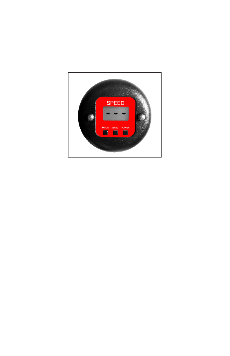
2.1 Display .......................................................................................... 17
2.2 Batteries ............................................................... 17
2.2.1 Removing Batteries ...................................................... 19
2.2.2 Battery Charger .............................................................. 19
2.3 Serial Communications Port ............................ 19
3. Performance Tips ...................................................... 20
3.1 How Radar Works ............................................ 20
3.2 Interference Sources and Remedies ............... 21
3.2.1 Angular Interference (Cosine Eect)........................ 21
3.2.2 Electromagnetic Interference (EMI) ........ 23
3.2.3Feedback Interference ........................... 23
3.2.4 Radio Frequency Interference (RFI) ...... 23
3.2.5 Scanning ................................................. 24
3.2.6 Environmental Factors —Wind, Rain, & Snow ....... 24
4. Care, Cleaning, and Storage ........................................ 25

SURFACE VELOCITY RADAR (SVR)™ USER’S MANUAL
SURFACE VELOCITY RADAR (SVR)™ USER’S MANUAL SURFACE VELOCITY RADAR (SVR)™ USER’S MANUAL
5
5. Specifications ........................................................... 26
5.1 Measurement Specifications ................................... 26
5.2 Factory Default Settings ................................... 26
5.3 Antenna Parameters ......................................... 26
5.4 Voltages ................................................................. 27
5.5 Power Consumption Parameters ........................... 27
6. Legal Requirements .................................................... 28
6.1 FCC Document ............................................... 28
7. Frequently Asked Questions (FAQ) .......................... 29
8. Service ........................................................................ 35
8.1 Warranty ......................................................... 35
8.2 Service Return Procedure ................................ 36
8.3 Maintenance and Repair Record ...................... 37
9. How to Order Additional Products ............................... 38
User Notes ......................................................................... 39
Index ................................................................................... 40

SURFACE VELOCITY RADAR (SVR)™ USER’S MANUAL
6
SURFACE VELOCITY RADAR (SVR)™ USER’S MANUAL
SVR Features
The SVR is a hand-held surface velocity radar (SVR) gun specically designed
to measure the surface velocity of water—great for use in streams and rivers.
The standard package includes:
• radargunwithsurfacevelocitymeasurementsoftware
• communicationsport
• two rechargeable batteries
• Black&Decker®VersaPak™2-port battery charger
• user’smanual
• hardcase
• certication
• two-yearfullwarranty.
The SVR operates using Black & Decker®VersaPak™rechargeable batteries,
which are available at hardware stores and Decatur Electronics.
The radar gun features a tilt sensor system, which internally compensates for
the cosine error eect of the vertical (pitch-down) angle of the gun to the
target. It is not necessary to manually set the tilt sensor.
Also, the software compensates for the horizontal (yaw) angle that is created
when the gun is aimed at a target from an angle, which is greater than 10°
from the parallel alignment of the gun to the target.
The SVR also features a data communications port, so it is possible to connect
the gun to external devices such as a PC.

SURFACE VELOCITY RADAR (SVR)™ USER’S MANUAL
SURFACE VELOCITY RADAR (SVR)™ USER’S MANUAL SURFACE VELOCITY RADAR (SVR)™ USER’S MANUAL
7
About This Manual
Note the following symbols in this manual.
indicates a warning message about safety precautions.
Please read it carefully.
indicates a helpful tip or precaution to note.
1. Quick Start
1.1 Initial Set Up
The SVR is easy to use. To operate, simply
• chargeandinsertthebatteries
• powerup
• aimatthetarget
• setthehorizontalanglepositionoftheguntotarget
• pullthetrigger,andrecordthevelocity.
1.1.1 Insert the Batteries
Remove the Black & Decker®VersaPak™batteries from their package and
charge them according to the VersaPak™instruction sheet (see section
2.1.2 Battery Charger for more about using the battery charger.) Insert the
batteries into the handle grip by pushing them into the receptacles in the
bottom of the handle until you hear them snap into place.
Figure 1.1.1 Insert the batteries into the handle grip.
* VersaPak™ is a registered trademark of the Black & Decker Company.

SURFACE VELOCITY RADAR (SVR)™ USER’S MANUAL
8
SURFACE VELOCITY RADAR (SVR)™ USER’S MANUAL
1.2 Power
Press and release the POWER button; the unit will immediately
power up. Press and hold the button down for more than one
second to turn o the unit.
Figure 1.2 The SVR display after turning on the power
The SVR has a power save timeout of 5 minutes. If
the gun is left ON for more than 5 minutes without
any buttons pressed or the trigger pulled during that
time, the gun will shut itself o.
1.3 Menu Options
To change a menu option, enter the Menu Mode by pressing the
MODE button. To advance to the next option, press the MODE
button again. To change an option value, press the SELECT button
while the menu option is displaying. The current value, the value
that was last set, is the rst value to display the next time you enter
the menu option. Repeat these steps until you display the desired
value. The radar gun continues to operate in the background while
it is in Menu Mode.
The SVR exits Menu Mode and returns to the main operating mode
if, after 6 seconds, you do not press the MODE or SELECT button.
The menu options are:
Display Function
bL Backlight (on/o)

SURFACE VELOCITY RADAR (SVR)™ USER’S MANUAL
SURFACE VELOCITY RADAR (SVR)™ USER’S MANUAL SURFACE VELOCITY RADAR (SVR)™ USER’S MANUAL
9
Figure 1.3a The mode for backlight, on, and o
Display Function
COS Cosine correction angle for the horizontal
(yaw) angle (the valid range is 0° to 60° in
increments of 5°)
Figure 1.3b The mode for selecting the horizontal (yaw) angle
Display Function
U “Eur” displayed for meters per second.
“USA” displayed for feet per second.
Figure 1.3c The mode for selecting meters per second
or feet per second

SURFACE VELOCITY RADAR (SVR)™ USER’S MANUAL
10
SURFACE VELOCITY RADAR (SVR)™ USER’S MANUAL
Display Function
A Vertical Angle Display. This is used
to verify that the SVR is reading
vertical angle correctly. The
vertical angle may be calibrated
rst putting the gun in a level
position, then pressing the Mode
and Power buttons simultaneously
for two seconds. (The Mode button
must be pressed rst to avoid
shutting o the gun). The display
will very briey change to “CAL”
when the self-calibration has been
performed.
Display Function
SEN Sensitivity Display and Adjustment.
Higher numbers tell the gun to
pickup surface velocity from a
further distance. Lower numbers
reduce the distance. If the
sensitivity is too high the indicated
velocity may be unpredictable and
erratic. The default value should
work well in most situations.

SURFACE VELOCITY RADAR (SVR)™ USER’S MANUAL
SURFACE VELOCITY RADAR (SVR)™ USER’S MANUAL SURFACE VELOCITY RADAR (SVR)™ USER’S MANUAL
11
1.4 Measuring Surface Velocity
To begin a velocity measurement, point the radar gun at the
water and pull and release the trigger. The surface velocity can
be measured owing toward or away from the gun. The decimal
point ashes while the SVR begins the measurement process. The
decimal point stops ashing when the measurement is stable. The
displayed velocity will continue to update as long as the trigger
is in the Down position. When the trigger is pulled and released
to bring it to the Up position the measurement will be locked and
displayed.
WARNING
Do not put the radar gun in the water. This will damage it. The SVR
measures the water surface only from outside the water.
Figure 1.4a The SVR displaying a 2.4 f/s
water-surface velocity
When the trigger is in the ON position, the SVR begins measuring
the surface velocity. The decimal point on the display will continue
to ash until the velocity stabilizes. The decimal point will stop
ashing when the SVR has performed enough measurements
to display an averaged and reliable velocity. This velocity will
continue to update as long as the trigger is in the ON position.

SURFACE VELOCITY RADAR (SVR)™ USER’S MANUAL
12
SURFACE VELOCITY RADAR (SVR)™ USER’S MANUAL
• TheUserpullstriggerON.Thedisplayshows“--.-”.
The leading “-”keeps ashing, indicting SVR is
taking measurements. The velocity is updated once
per second. This velocity may vary signicantly while
the SVR focuses its data processing. Towards the end
of the rst ten seconds, the displayed velocity will be
accurate.
• After10secondsthedisplayupdatesto“0X.X”.The
leading“0”means10secondshavepassed.The“X.X”
is the average velocity over the last 10 seconds and
then keeps unchanged. The leading “0”keeps
ashing.
• After15seconds,thedisplayupdatesto“1X.X”.The
leading “1” means 10+5 seconds have passed. The
“X.X”istheaveragevelocityoverthelast15seconds
and then keeps unchanged. The leading “1”keeps
ashing.
• After20seconds,thedisplayupdatesto“2X.X”.The
leading “2” means (10+5+5) seconds have passed. The
“X.X”istheaveragevelocityoverthelast20seconds
and then keeps unchanged. The leading “2”keeps
ashing.
• After60secondshavepassed,theSVRhascompleted
ten separate 5-second batches of velocity
measurements. The display will indicate the average
of these measurements.
If the user pulls the trigger OFF at any time, the display reads the
average of all measurements up to that point. For example, “52.3”
means SVR calculated a velocity of 2.3m/s over a period of 35
seconds.
If there are uctuations of more than 0.5 to 0.8 f/s (0.15 to 0.24 m/s)
during a measurement interval, it is advised to review the nal value.
Consistent readings conrm the validity of the result, so we recommend
taking the measurement more than once.

SURFACE VELOCITY RADAR (SVR)™ USER’S MANUAL
SURFACE VELOCITY RADAR (SVR)™ USER’S MANUAL SURFACE VELOCITY RADAR (SVR)™ USER’S MANUAL
13
A hydraulics laboratory tested the SVR and discovered several
factors to consider when making measurements outdoors.
Because the SVR measures the Doppler eect from the water
surface, the SVR requires a certain amount of return energy. (See
section 3.1 How Radar Works.) Particulate material and/or oating
debris (seeding) on the surface and surface water roughness
provide this eect.
The SVR easily measures the velocity at which the particulate
material moves in high-ow conditions. This provides the accuracy
of the surface ow. For velocities of more than 1 to 2 f/s (0.30 to
0.60 m/s), oating debris and particulate material provide an ample
return signal to the radar gun for measurement. Water roughness
also gives a good signal return. Ripples and crosscurrents produce
velocities in all directions. During a measurement, the SVR reads
all the velocities and averages them into a resulting single value,
based on the amount of signal return to the antenna.
1.5 Angle Compensation
The SVR compensates for the cosine error eect occurring when
the position of the gun to the target creates an angle, because the
gun is not directly in line (parallel) with the target. The tilt sensor
automatically corrects the cosine error eect of a vertical angle. To
compensate for the eect of the horizontal angle, set the software
from the Menu Mode by pressing the MODE button to display
A, then press SELECT to display the angle at which you will be
aiming the gun. When the radar gun is not pointing directly in line
(parallel) with a target, the position of the gun to the target creates
a horizontal (yaw) angle. If this angle is greater than 10°, it creates
the cosine error eect. This eect results in spurious (unusually
low) velocity readings. (See section 3.2.1 Angular Interference for
more about the cosine error eect.)
The vertical cosine angle will always be calibrated at the factory
and should never need calibration in the eld. However, a new
application download may overwrite the locations where vertical
cosine angle calibration parameters are stored.

SURFACE VELOCITY RADAR (SVR)™ USER’S MANUAL
14
SURFACE VELOCITY RADAR (SVR)™ USER’S MANUAL
The vertical angle of the SVR may be recalibrated at any time by
leveling the gun and pressing the“mode” and“power” buttons at
the same time for more than one second. Press the “mode”button
slightly before the “power” button to make sure you don’t power
o the gun. The display will very briey indicate “CAL”. Run back
to the Angle menu item and check the angle. It should read zero
degrees when the gun is level. In actual use, a variance of a few
degrees doesn’t signicantly aect the displayed velocity.
If the vertical angle of the gun exceeds 60 degrees, the display
will indicate“—”. The angle measurement is not accurate over 60
degrees, and we cannot gaurantee accuracy above a 60-degree
angle.
1.5.1 Vertical Angle Compensation
Figure 1.5.1a The SVR tilted pitch-down at a 60° vertical angle.
The tilt sensor automatically compensates for the vertical angle at
which you aim the gun to the target. You do not need to manually
set the tilt sensor. However, you must hold the gun still at a
constant vertical angle while taking a velocity measurement.

SURFACE VELOCITY RADAR (SVR)™ USER’S MANUAL
SURFACE VELOCITY RADAR (SVR)™ USER’S MANUAL SURFACE VELOCITY RADAR (SVR)™ USER’S MANUAL
15
The SVR indicates when the pitch-down angle exceeds
60° by displaying“– – –”. While “– – –”appears in the
display window, the radar gun does not record velocity
measurements. To continue taking water surface velocity
velocity measurements, tilt the gun to an angle less than 60°
until the
“– – –” indicator no longer appears.
Figure 1.5.1b The display when the vertical
(pitch-down) angle exceeds 60°
1.5.2 Horizontal Angle Compensation
Aiming the radar gun at the target at a horizontal angle
greater than 10° creates a cosine error, which results in the
radar displaying a spurious reading. To eliminate or greatly
reduce this error, set the horizontal angle compensation
option to the angle that you plan to aim the radar gun to the
target. Then aim and hold the gun at this set angle during
the entire velocity measurement.

SURFACE VELOCITY RADAR (SVR)™ USER’S MANUAL
16
SURFACE VELOCITY RADAR (SVR)™ USER’S MANUAL
Figure 1.5.2a When the radar gun is not parallel with the
target (the ow of the water) the positioning creates a
horizontal (yaw) angle.
To set the horizontal angle compensation option, press the MODE
button until an A appears in the display. Then press the SELECT
button. Each time you press the SELECT button, a 0, 5, 10, 15, 20,
25, 30, 35, 40, or 75 appears, representing the horizontal angle
degrees in which you plan to hold the gun. Select the angle by
displaying the number until the radar gun times out. Now the
gun is set at this angle selection and remains in this mode until
you change it. This setting will appear the next time you enter this
menu option.
Figure 1.5.2b The horizontal angle setting for 0°

SURFACE VELOCITY RADAR (SVR)™ USER’S MANUAL
SURFACE VELOCITY RADAR (SVR)™ USER’S MANUAL SURFACE VELOCITY RADAR (SVR)™ USER’S MANUAL
17
2. Components
The SVR surface velocity measurement radar gun is extremely durable
and has an easy-grip Black and Decker designed handle. The gun uses
rechargeable Ni-Cad batteries, which are conveniently available at
hardware stores and Decatur Electronics.
2.1 Display
The face panel includes a 3-digit velocity display and three
buttons—MODE, SELECT, and POWER. Using the MODE and SELECT
buttons, it is possible to control the backlighting of the display,
cosine error correction of horizontal angle, and (if enabled) the serial
communication output mode.
The display is logically divided into two portions. The left digit is a
time indicator. The middle and right digits display the velocity.
2.2 Batteries
The SVR comes with a Black & Decker VersaPak™Rechargeable
Battery Starter Kit: two nickel-cadmium (NiCd), silver label,
3.6-volt VersaPakTM batteries and a two-port AC auto charger (part
number P702-VP135). For increased runtime, please use nickel
metal hydride (NiMH), gold label, VersaPak™batteries. Please read all
the instructions and warnings on the VersaPak™instruction sheet to
ensure proper use and storage of your batteries.
Use the battery caps provided with the batteries when storing or
carrying them, so metal objects (keys, coins, etc.) do not come in
contact with the exposed metal end. Remember to remove the caps
before placing the batteries in the charger or SVR.
When the batteries are low, bAt appears in the display.

SURFACE VELOCITY RADAR (SVR)™ USER’S MANUAL
18
SURFACE VELOCITY RADAR (SVR)™ USER’S MANUAL
Figure 2.1 The display indicating low batteries
• When the radar is transmitting, the SVR consumes
roughly three times as much power from a battery
than when it is not transmitting. Keep this in mind to
maximize the battery life.
•The device draws a small amount of power from the
batteries even when the power is o. When the device is not
in use for extended periods, remove the batteries to save the
charge.
WARNINGS
•IMPORTANT: Do not combine a NiCd (silver label) battery
with a NiMH (gold label) battery in the same gun. It can
damage the batteries.
•IMPORTANT: Using batteries that have mismatched
voltages (one battery fully charged and another with
low voltage) can cause the device to incorrectly power up.
•Never attempt to open a battery. If the housing breaks or
cracks, immediately discontinue its use, and do not recharge it.
•Do not incinerate the batteries. They can explode.
If you have problems or questions about your batteries, contact
Decatur Electronics at 800.428.4315, Black & Decker at 800.54.
HOWTO, or a local Black & Decker service center. (See the Tools
Electric section in the Yellow Pages.)

SURFACE VELOCITY RADAR (SVR)™ USER’S MANUAL
SURFACE VELOCITY RADAR (SVR)™ USER’S MANUAL SURFACE VELOCITY RADAR (SVR)™ USER’S MANUAL
19
2.2.1 Removing Batteries
To remove the batteries, press the red button with your
thumb while pulling out the battery.
2.2.2 Battery Charger
Only charge the batteries with the VersaPak™battery
charger. It is normal for the charger to hum and for the
batteries and charger to become warm while charging.
If a battery does not charge properly, check the battery
charger to see if it is working or move it somewhere with a
temperature between +40°F and +105°F (+4°C and +41°C).
Unplug the charger when it is not in use.
2.3 Serial Communications Port
An activated serial communications port and 20-foot custom RS232
communications cable (part number S769-100) is available for
ordering for recording and analyzing velocity data. With the port,
connection of the SVR to external devices, such as a PC, is possible.

SURFACE VELOCITY RADAR (SVR)™ USER’S MANUAL
20
SURFACE VELOCITY RADAR (SVR)™ USER’S MANUAL
3. Performance Tips
Understanding potential radar interference and what you can do when it
occurs can greatly increase the radar gun’s performance.
3.1 How Radar Works
Determining a velocity begins with the radar gun transmitting
and directing a beam of microwave energy (radio waves) at an
approaching (or receding) target. When energy from this beam
strikes the target, a small amount of energy from this beam is
reected back to the antenna in the radar device. The reected
signal frequency shifts by an amount proportional to the velocity
of the target. This is known as the Doppler eect. The radar
device then determines the target velocity from the dierence in
frequency between the transmitted and reected signal.
When the antenna transmits the beam of radio waves, the beam
forms an elliptical pattern on the target area. The beam’s size
depends on the distance between the antenna and the target.
The horizontal beam width is 12°. The detection area becomes
larger as it becomes farther away from the antenna.
Figure 3.1 Radar beam detection area
Other manuals for SVR DUAL
1
Table of contents
Other Decatur Electronics Radar manuals

Decatur Electronics
Decatur Electronics SI-3C User manual

Decatur Electronics
Decatur Electronics Genesis II Select Directional User manual

Decatur Electronics
Decatur Electronics Genesis VP Directional User manual

Decatur Electronics
Decatur Electronics RAILMASTER-VP User manual

Decatur Electronics
Decatur Electronics SI-2 User manual

Decatur Electronics
Decatur Electronics GHD User manual

Decatur Electronics
Decatur Electronics SVR DUAL User manual

Decatur Electronics
Decatur Electronics Railmaster User manual

Decatur Electronics
Decatur Electronics GHD User manual

Decatur Electronics
Decatur Electronics Genesis VP Directional User manual