AGF Grow More GM10 User manual

Assembly Instructions
MODEL: GM10
GREENHOUSE SIZE: 13' 3 7/8"L x 10' 1/2"W x 8' H
406cm L x 306cm W x 243cm H
EXTENSION SIZE: 6' 6 3/4"L x 10' 1/2"W x 8' H
200cm L x 306cm W x 243cm H
PLEASE READ INSTRUCTIONS CAREFULLY BEFORE ASSEMBLY
Item No. Model No. Packing List
GM10
GM10 ext
2553100
2553150
AL No.1 AL No.2 AL No.3 PC No.1 PC No.2
1CTN 1CTN 1CTN 2CTNS
1CTN 1CTN
Customer Support
1-888-888-9050

CONTENTS
1. Assembly Advice................................................................Page 1
2. Product Features ................................................................Page 3-4
3. Parts List .............................................................................Page 5-8
8. Framework &Panel Assembly ..........................................Page 16-32
7. Roof Vent Assembly ..........................................................Page 15
5. BaseAssembly ..................................................................Page 9-12
6. Door Assembly ...................................................................Page 13 -14

Click
Functions and Features:
2. Easy and fast assembly.
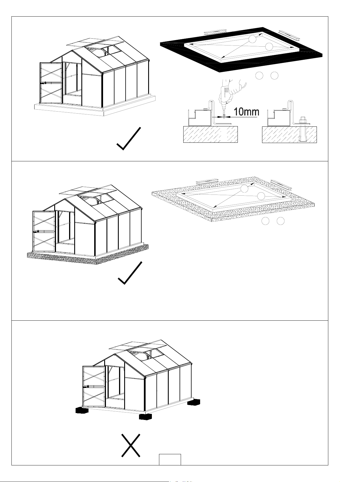
7mm/10mm
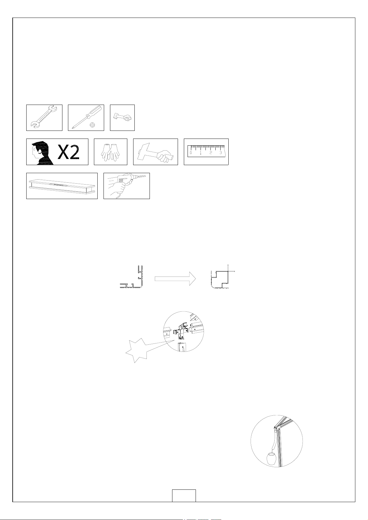
Free Tool Free Tool Free Tool
1.Forsafetypurposes,westronglyrecommendthattheproductwillbeassembledby at least twopeople.
Assemblyand Maintenance Advice
2.Somepartshave sharpedges.Please becarefulwhenhandlingcomponents.Always wear gloves, shoes
andsafetygogglesduringassembly.
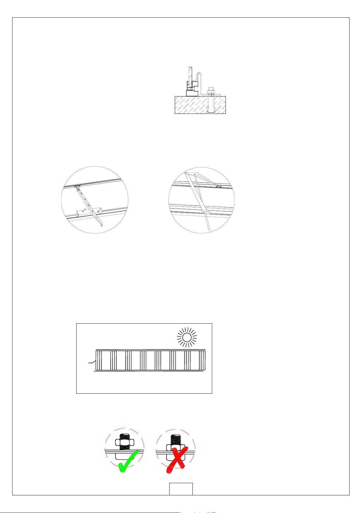
3.DONOTclimborstandontheroof,heavyarticlesshouldnotbeleanedagainst the greenhouse.
4.Keeproofandguttercleanofsnow,dirt&leaves.Largeamountsofsnowonroof can damage the product,
makingitunsafetostandbelowor nearby.
5.Whenyourproductneedscleaning,use amilddetergentsolutionandrinse withcoldclean water.
Donotuse acetone,abrasive cleanersorotherspecialdetergentstoclean the panels.
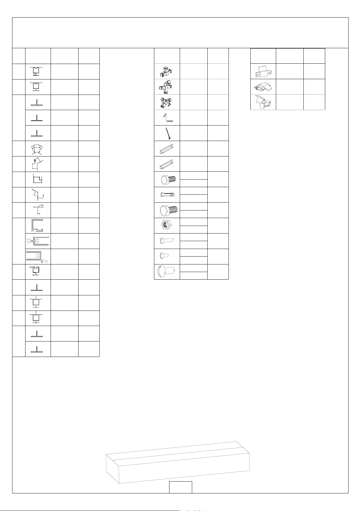
1. Incomparison toatraditional greenhouse structure,all mainprofiles are
manufactured inasquare hollowsection design,resulting inastronger
3.The unique design allowsthe greenhouse tobe easilyextended at any stage
in2mlong sections as detailed inthe tableof Front Page;
more weather resistant product.
4. The Grange Series greenhouses include gutters
You can also easilyconnect these toasuitable
and aluminiumdownpipes toharvest the rainwater.
tank.
3

Manualopener Automatic opener
5. Asteel base isnot required as the aluminiumbase frameisfixed to
the necessary concretefootings withthe expansion boltsprovided,
alternativelyyou can easilysecure it toatimber base withtimber
screws(not provided).
Expansion screw
/Concreteground
6. The Grange Series greenhouses comestandard withManual opening
arms. Automaticopeners can be purchased seperatelyand fitted to
any windowvent. Werecommend twoautomaticvent openers be fitted
7. Please ensure the roof ventsare not installed intothe end roof bays of
the greenhouse as thisiswhere you need the bracing.
8.Each PolycarbonatePanel comes withUV protected properties.
Please ensure the clear filmwiththe text faces out, toward the
sun Remove bothfilmsbefore installation of the panels.
toeach vent inthe samepositions the standard manual vent arms.
4
SUN
POLYCARBONATEPANEL
White Film
Transparent Film
PC
sheet
Two sidesof PC sheet are covered with thin films, one side'sfilm is white, another
istransparent. The UV-protected side of PC sheet is covered with white film and
mustface towardsthe Sun.
9. Nutsnot tobetightened beforetheend ofassembly!Unless otherwisestated,do not
tightenthe bolts/nuts/screwsuntil theshed isfinallyerected!

L05A 4
QTY.
L01A
L03E 1
3
NO.PART
L03F 1
L08A 6
L01B 2
L01C 2
L04B 5
D17 4
QTY.
NO.
PART
J01R/L 2/2
J03 4
J02 2
J06R/L 2/2
D07 5
5
L03C 1
L03D 1
L05B 1
46
46
L05G 4
L18A
L16A 1
2
L18B 2
L18C 1
L16B 1
A14 8
16
L16C 1
L01D 1
L04A 1
16
L30 4
Z09
5X15
S08
M8X60
M03
M6
S05
M6X12
Z02
4X16D
ALU.BOXNO.1
5
J93
J92
4
4
1
2
3
7
4
5
6
8
9
10
2
2
4
2
2
2
QTY.
NO.
PART
A06
A07
A08
A09
A10
A11
11
GM10 ALU BOX NO.1

ALU.BOXNO.2
6
L02A 4
QTY.
NO.
PART
L08B 4
L02B 4
L06 2
L07 4
L05C 4
L05D 4
L05B 4
L15A 4
L09 4
L19 8
L20 4
L21 4
L04E 4
QTY.
NO.
PART
A01 8
A69 4
90
8
24
16
D07 8
8
82
16
A70 4
L22 6
QTY.
NO.PART
J03 2
L03B 2
L03A 2
2
1
J04 1
L05E 2
L05F 4
J07 2
S05
M6X12
S11
M6X20
M03
M6
Z02
4X16D
Z10
5X30
Z04
4X8
S08
M8X60
2
A08
A12
A13
2
1
3
4
5
6
7
8
9
10
11
12
13
14
GM10 ALU BOX NO.2

ALU.BOXNO.3
7
L02A 2
QTY.
NO.
PART
L08B 2
L02B 2
L06 1
L07 2
L05C 2
L05D 2
L05B 2
L15A 2
L09 2
L19 4
L20 2
L21 2
L04E 2
QTY.
NO.
PART
A01 4
A69 2
48
4
12
8
D07 4
4
44
8
A70 2
L22 3
QTY.
NO.PART
J03 2
L03B 2
L03A 2
2
1
J04 1
L05E 2
L05F 4
J07 2
S05
M6X12
S11
M6X20
M03
M6
Z02
4X16D
Z10
5X30
Z04
4X8
S08
M8X60
2
A08
A12
A13
2
1
3
4
5
6
7
8
9
10
11
12
13
14
GM10 2EXT. ALU BOX NO.3

QTY.
NO.
PART
Y6 4
Y7 2
Y9 2
QTY.
NO.
PART
Y1 1
Y2 2
Y4 1
Y5 1
QTY.
NO.
PART
Y1 1
Y2 3
Y4 1
Front Assembly Back Assembly
1X2 Sections Assembly
Door Assembly
QTY.
NO.
PART
Y11 2
Y3 1
Y10 2
8
PCBoxNo. 1
No.1
PCBoxNo. 2
PC Box
No.2

ab
ab
=
ab
=
ab
9
Expansionscrew
/ Concreteground
*It iscrucialthe a+bdimensionsarethe sametoensurethe baseissquare.
Support at the cornersonlyisnot adequate.

Front Assemby Back Assembly
10
4Section Assemby
123 4
*W= OuterWidthof BaseProfiles
*L=OuterLengthof BaseProfiles
*a=b=OuterDiagonalofBaseProfiles
*a1=b1=InnerDiagonalof BaseProfiles
4x3M
W
L
a=b
a1=b1
6x3M 8x3M 10x3M 12x3M 14x3M 16x3M 18x3M etc.
(mm)
(mm)
(mm)
(mm)
3059.6
4060.2 6062.2 8064.2 10066.2 12068.2 14070.2 16072.2 18074.2
5083.9 8625.1 10520.9 12450 14399 16360.8 18331.3
4958.9 8510.2 10409.7 12341.7 14293.1 16256.6 18228.6
6790.5
6670.7
3059.6 3059.6 3059.6 3059.6 3059.6 3059.6 3059.6
Item No.
Dimensions
GM10

11
*Thebasicmodel,GM10,canbeeasilyextendedby adding
a`2SectionAssembly'eachtimeforalonger size
2Section
Assembly 2Section
Assembly 2Section
Assembly
Middle
Section Middle
Section
GM10 GM10ext
GM10+Ext(1)
Front Rear

12
W05
S03
W05
W05
*Thisshowsalayout forW05's positionswhereit isplaced
inthe middleof PCpanelforeachsection.
Rear
Front
GM10 +Ext(1)
*All measurementsinabovediagramareinmm.

12
456
123
4
5
6
Y11
3
L18A
L18C
L18B
L16C
L05G
A14
A14
L16C
L18C
Z09
A14
L18A
L18C
Z09
L16C
L18B
Z09
A14
L18A
L18B
Z09
L05G 4
QTY.
L18A
L16A 1
2
NO.PART
L18B 2
L18C 1
L16B 1
A14 8
8
8
16
L16C 1
Y11 2
L05G
13
Z09
M03
M6
S05
M6X12
Door 1Assembly
5X15

7
11
9
10 12
78
9
10
12
Y11
8
L18A
L18B
L16B
L16A
L05G
A14
A14
L16A
L18B
Z09
A14
L18A
L18B
Z09
L16A
L16B
Z09
11
A14
L18A
L16B
Z09
L05G
14
Door 2Assembly

15
QTY.
NO.PART
L15A 1
L19 2
L20 1
L21 1
A01 2
2
2
4
S11
M03
Z02
Z04 6
M6X20
M6
4X16D
4X8
Y10 1
Roof Vent Assembly Z02
Z02
Z02
Z02
L15A
L20
L21
L19
L19
Y10

12
3
L08B L08A
A06
J01R/L
L08A J01R/L
L08B
J03
L08B
J01R/L
L08A J01R/L
L08B
L08A
1
1
2
2
22
3
3
4
4
L08A&B
L08A&B
L08A L08A L08A L08B
L08B
L08B
L08B
L08A L08A L08A
J03
L08B
L08B
16
Assembleall D07 followed bypreviousPage 16 aftereachbaseprofileisconnected.
D07
S08
A06
A08
A08
A07 A07
QTY.
NO.PART
L08B 4
L08A 6
2
2
A06
A07
J01R/L 2/2
6
A08
J03 6

17
234
L03C L03D
L01A
L03A
5A09&A10
L07 L01A
7
6
L07
L03A
L01A
L03C L03D
L01A
L03A
L03A
L07
L07
1234
5
5
6
7
7
6
CORRECT WRONG
Ensure orientation of the L07 profile
iscorrect as per detail.
1
L01A
A08
A12
QTY.
NO.
PART
L01A 2
L03A 2
L03C 1
L03D 1
L07 2
1
1
A09
A10
2
A12

2*S05
2
1
L04B
L04B
L04B L04B
18
Slide 2xS05 intoeach L04B
345
L05B
L05A
L05A
L03C
L08A
L04B
Y2 Y2 Y2
L05A L05B L05A
L04B L04B L04B
1
1
4
4
55
3223
and tighten themat each end.
QTY.
NO.
PART
L04B 3
L05A 2
L05B 1
Y2 3
12
12
S05
M6X12
M03
M6

19
L03B L03B
2
1
1
2
2
S05x3pcs
L02A
L02A
L02A
L05B L05C
L05B L05C
3
L02A
L08B
L05C
L08B
L03A
L05B
L05B
56
4
L05B
8
L05C
7
8
56
4
37
37
6
5
48
A12
A13
QTY.
NO.PART
14
12
S05
M6X12
M03
M6
L02A 2
L03B 2
L05B 2
L05C 2
1
A13

20
55
4
3
4
3
345
L05F
L03K L05F L05F
L05F L05E
L05E
L05F
L05E
L05F
QTY.
NO.
PART
20
18
S05
M6X12
M03
M6
L02A 2
L05B 2
L01A 1
L01D 1
L07 2
L05C 2
L05E 2
1
1
A09
A10
L05F 4
This manual suits for next models
3