Cedar Wood Information
Cedar is prone to absorption of moisture to attain balance with the
surrounding atmosphere.
As a result this moisture can track to the inside of the greenhouse
particularly in the areas that are subject to the greatest weathering.
Because of the fibre structure of the cedar it will also dry very quickly
which often will leave a mark where the extractives have been
released. These extractives are the oils naturally present in the cedar
that make it resistant to rot.
As the wood weathers it gradually changes colour the first stage is
the darkening of the wood as water soluble extractives are drawn to
the surface. In time this trend reverses and the wood gradually turns
silver grey.
Insurance
Please note that insurance companies usually cover greenhouses
automatically. Contact your insurance company to confirm your
cover.
Guarantee
Growhouse grants a guarantee of 10 years which covers replacement
of faulty parts. The guarantee does not cover glass transport
assembly freight etc.
Growhouse grants a guarantee of 2 years on painted parts. Note that
marks in the painting may occur due to suspension of the profiles.
The guarantee is invalid if the greenhouse is not assembled according
to these instructions.
Complaints
All our greenhouses are built to high standards of quality. However
should a complaint occur please contact your dealer.
ptional Extras
•Steel Base
•Autovent
•Louvre Vent
•Benching
•Shelving
•Blinds
•Waterbutt
•Irrigations System
Please visit our website for more details on the above products.
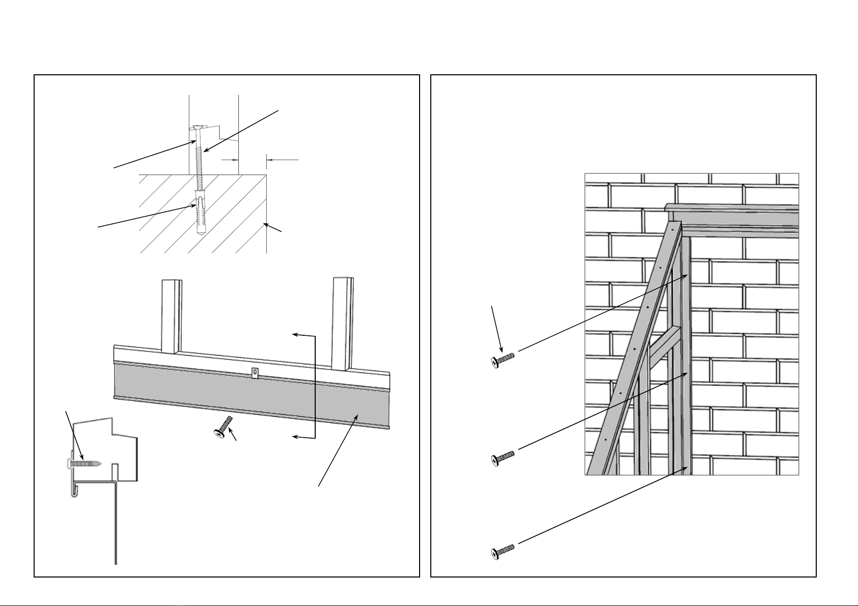
Use a 9mm HSS drill bit to drill through the ti
mber cill. Drill into the
base using an 8 x 150mm masonry drill to a depth of 110mm from
the top.
Fixing Greenhouse to Wall
Refer to Step 10
Using screw type SC057 with WA501 and FX200 fix through the
abutting post and into wall.
Please Note: When fixing the structure to the lean to wall the fixings
should be positioned equally down the structure’s abutting post at
points that will hold firmly into the wall i.e. into the solid brick rather
than the brick joints.
Tools Required for Assembly
•PZ2 Screwdriver
•Electric Screwdriver (Optional)
•Drill
•8mm Masonry Drill
•A Clamp When Fixing Sections Together (Recommended)
•Spirit Level
•Tape Measure
Roof Vent
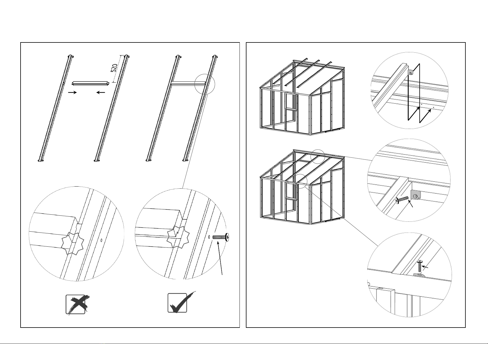
Fix casement stays or autovents with screw type SC004 and using the
pre fitted side vent as a guide.
Glazing Notes
Refer to Step 11.
Prior to glazing remove the pre fitted cappings on the sides and
ends noting their positions.
We recommend 2 people for glazing the structure.
Safety goggles and gloves are required when handling glass.
Caring for Your Greenhouse
•Clean the gutter for leaves etc.
•Remove greater snow loads from roof.
•Take precautions against snow falling down from for instance a
tree or a roof.
•Secure door and windows preventing wind damage.
Dear Growhouse Customer,
Please read ALL these instructions before assembly.
The assembly of your new Growhouse greenhouse requires no
technical knowledge. However it is important that the assembly
instructions are followed carefully.
All fixings are found in bags 2 to 10.
Extra fixings may be included in your kit.
Fix casement stays or auto vents with screw type SC004 and using the
pre fitted side vent as a guide.
Greenhouse Base Notes
Your greenhouse must be fixed onto a suitable base.
The base is not included however an optional steel base can be
purchased separately.
The following options are available:
•Steel Base Coloured Green can be Purchased Separately
•Single Brick Coarse
•Concrete Slab
•Solid and Level Flagstones
The measurements must match that of the base plan. A suitable
foundation on which to construct the base must be laid depending on
local ground conditions. Ensure the base is square and level and
diagonal measurements are equal.
Fixing Greenhouse to Base
Refer to Step 9.
Check that the structure is square ensuring dimensions across
diagonals are even before securing to the base.
Steel Base
Position a fixing bracket on the inside of the steel base and using
screw type SC125 fix through the bracket and into the greenhouse
cill.
Position and fix all the brackets supplied evenly around the
structure’s base.
Constructed Base
When fixing the structure down to a brick plinth or concrete base
the fixings for the base should be positioned proportionally around
the structure’s timber cill at points that will hold firmly into the base
i.e. into the solid brick rather than the brick joints.