AGP DM5 User manual

GB Diamond core drilling machine. Safety instructions 2
DDiamant-Kernbohrmaschine Sicherheitshinweise 15
FCarotteuse Au Diamant Instructions de sécurité 26
E
Perforadora Con Corona De Diamante
Instrucciones de seguridad 38
ISistema Di Foratura Al Diamante Indicazioni per la sicurezza 50
NL Diamant boormotor Veiligheidsvoorschriften 62
For your personal safety, READ and
UNDERSTAND before using.
SAVE THESE INSTRUCTIONS FOR
FUTURE REFERENCE.
ORIGINAL INSTRUCTIONS

GB
2
7.
1. Motor
2. Tubular Spirit Level
3. Gear Selector
4. Release Button
5. Lock Screw (Side Handle)
6. Spindle
Model DM5
Power Input 1800W
Voltage
110-120 V~ 50-60 Hz, 220-240 V~ 50-60 Hz (
See machine nameplate)
No Load /Full Load min-1 Speed 1 1300 / 720
Speed 2 2300 / 1260
Capacity-Wet 132mm (5-1/4")
Arbor Thread 1-1/4"UNC & 1/2" BSP
Neck Diameter 60mm
Protection Class Class I with PRCD / GFCI
Dimensions (mm) 450mm x 105mm x 280mm
Net Weight 4.9 kg (10.8Lbs)
TECHNICAL DATA
1.
2.
3.
4.
5.
6.
8.
9.
10.
11.
12.
7. Water Feed Valve
8. Side Handle
9. Trigger Switch
10. Lock Button
11. Main Handle
12. Power Supply Cable

3
GB
General Safety Rules
WARNING! Read all safety warnings and all instructions. Failure to follow the warnings and
instructions may result in electric shock, re and/or serious injury.
Save all warnings and instructions for future reference.
The term“power tool”in the warnings refers to your mains-operated (corded) power tool or battery-operated
(cordless) power tool.
1. WORK AREA SAFETY
a. Keep work area clean and well lit. Cluttered and dark areas invite accidents.
b. Do not operate power tools in explosive atmospheres, such as in the presence of ammable
liquids, gases or dust. Power tools create sparks which may ignite the dust or fumes.
c. Keep children and bystanders away while operating a power tool. Distractions can cause you to lose
control.
d. Never leave the electric power tool unattended. Only leave the machine when the tool in use has come
to a complete standstill.
2. ELECTRICAL SAFETY
a. Power tool plugs must match the outlet. Never modify the plug in any way. Do not use any adapter
plugs with earthed (grounded) power tools. Unmodi ed plugs and matching outlets will reduce risk of
electric shock.
b. Avoid body contact with earthed or grounded surfaces, such as pipes, radiators, ranges and
refrigerators. There is an increased risk of electric shock if your body is earthed or grounded.
c. Do not expose power tools to rain or wet conditions. Water entering a power tool will increase the risk
of electric shock.
d. Do not abuse the cord. Never use the cord for carrying, pulling or unplugging the power tool. Keep
cord away from heat, oil, sharp edges or moving parts. Damaged or entangled cords increase the risk
of electric shock.
e. When operating a power tool outdoors, use an extension cord suitable for outdoor use. Use of a
cord suitable for outdoor use reduces the risk of electric shock.
f. If operating a power tool in a damp location is unavoidable, use a residual current device (RCD)
protected supply. Use of an RCD reduces the risk of electric shock.
3. PERSONAL SAFETY
a. Stay alert, watch what you are doing and use common sense when operating a power tool. Do
not use a power tool while you are tired or under the in uence of drugs, alcohol or medication. A
moment of inattention while operating power tools may result in serious personal injury.
b. Use personal protective equipment. Always wear eye protection. Protective equipment such as dust
mask, non-skid safety shoes, hard hat, or hearing protection used for appropriate conditions will reduce
personal injuries.

GB
4
c. Prevent unintentional starting. Ensure the switch is in the o-position before connecting to power
source and/or battery pack, picking up or carrying the tool. Carrying power tools with your nger on
the switch or energising power tools that have the switch on invites accidents.
d. Remove any adjusting key or wrench before turning the power tool on. A wrench or a key left
attached to a rotating part of the power tool may result in personal injury.
e. Do not overreach. Keep proper footing and balance at all times. This enables better control of the
power tool in unexpected situations.
f. Dress properly. Do not wear loose clothing or jewellery. Keep your hair and clothing away from
moving parts. Loose clothes, jewellery or long hair can be caught in moving parts.
g. If devices are provided for the connection of dust extraction and collection facilities, ensure these
are connected and properly used. Use of dust collection can reduce dustrelated hazards.
h. Do not let familiarity gained from freuquent use of tools allow you to become complacent and
ignore, tool safety principles. A careless action can cause severe injury within a fraction of a second.
4. POWER TOOL USE AND CARE
a. Do not force the power tool. Use the correct power tool for your application. The correct power tool
will do the job better and safer at the rate for which it was designed.
b. Do not use the power tool if the switch does not turn it on and o. Any power tool that cannot be
controlled with the switch is dangerous and must be repaired.
c. Disconnect the plug from the power source and/or battery pack from the power tool before making
any adjustments, changing accessories, or storing power tools. Such preventive safety measures
reduce the risk of starting the power tool accidentally.
d. Store idle power tools out of the reach of children and do not allow persons unfamiliar with the
power tool or these instructions to operate the power tool. Power tools are dangerous in the hands of
untrained users.
e. Maintain power tools. Check for misalignment or binding of moving parts, breakage of parts and
any other condition that may aect the power tool‘s operation. If damaged, have the power tool
repaired before use. Many accidents are caused by poorly maintained power tools.
f. Keep cutting tools sharp and clean. Properly maintained cutting tools with sharp cutting edges are less
likely to bind and are easier to control.
g. Use the power tool, accessories and tool bits etc. in accordance with these instructions taking into
account the working conditions and the work to be performed. Use of the power tool for operations
dierent from those intended could result in a hazardous situation.
h. Keep handles dry, clean and free of oil and grease. Slippery handles do not allow for safe handling and
control of the tool in unexpected situations.
5. SERVICE
a. Have your power tool serviced by a quali ed repair person using only identical replacement parts.
This will ensure that the safety of the power tool is maintained.
b. Only use original parts for repair and maintenance. The use of incompatible accessories or spare parts
can result in electric shocks or other injuries.

5
GB
Symbols used in this manual
V…….......volts
A…….......amperes
Hz……......hertz
W……......watt
~………....alternating current
n
0
………..no load speed
min-1….....revolutions or reciprocation
per minute
......warning of general danger
.…with electrical earth
.......read these instructions
......always wear eye protection
......always wear a dust mask.
.....always wear hearing protection
.....wear safety-approved hard hat
do not dispose of electric tools,
accessories and packaging together
with household waste material
DRILL SAFETY WARNINGS
• Use auxiliary handle(s). Loss of control can cause personal injury.
• Hold power tool by insulated gripping surfaces, when performing an operation where the cutting
accessory may contact hidden wiring or its own cord. Cutting accessory contacting a "live" wire may
make exposed metal parts of the power tool "live" and could give the operator an electric shock.
• Never use the machine without the PRCD fault-current safety switch supplied.
• Always check the PRCD fault-current safety switch for correct functioning before starting a drilling
operation.
• Ensure that no water is allowed to get into the motor unit during operation.
• If you detect a leak in any part of the water supply system, shut the machine down immediately
and repair the fault. Water pressure should not exceed 70 psi (4 bar).
• Block off the working area and place warning signs on both sides of the wall when drilling through
from one side to the other.
• Take appropriate precautions to ensure that, in the event of a drilling core dropping out, no
personal injury or material damage will result.
• When drilling hollow components, check the flow route of the cooling water in order to prevent
damage.
INTRODUCTION
The machine is equipped with spirit levels which aid in aligning the tool. Use the Bull's Eye Level for vertical
aligning and the Tubular Level for horizontal aligning.
This machine is for the intended purpose of diamond core drilling of concrete, masonry, stone and similar
materials. The machine may be hand-held for drilling up to 80mm. For sizes above 80mm, it must be mounted
on a rig (drilling stand). The rig is not included.
All other uses which are not for the intended purpose are prohibited.
It is equipped with a water feed system which is required for the diamond core drilling process.

GB
6
It is equipped with a PRCD interrupter (portable residual current device) which must be used at all times. It is
equipped with a two speed mechanical gearbox for different core drill size ranges and features a mechanical
safety clutch. The motor has electronics for soft start, overload protection and thermal (overheating)
protection.
ELECTRICAL CONNECTION
The network voltage must conform to the voltage indicated on the tool name plate.
Under no circumstances should the tool be used when the power supply cable is damaged. A damaged
cable must be replaced immediately by an authorized Customer Service Center. Do not try to repair the
damaged cable yourself. The use of damaged power cables can lead to an electric shock.
WARNING:
This machine is equipped with a Portable Residual Current
Device (PRCD) also known as a Ground Fault Circuit Interrupter
(GFCI). Always use this device whenever using the machine to
reduce the risk of shock hazards. Test and reset the PRCD
device before each use. Press the “Test” button to test. Press the
“Reset” button to energize the circuit.
WARNING!: 110V UK machines are not equipped with a PRCD
portable residual current device or GFCI ground fault circuit interrupter. The machine must always be
used with an isolating transformer for protection in case an electrical fault should occur.
Use an RCD in a separate control box with one or more socket outlets in accordance with EN
60309-2 with the earthing contact position 1 h.
ASSEMBLY
1. Mount the handle clamp of the side handle onto the gearbox neck. Position the side handle perpendicular
to the main handle. Use the lock screw to tighten the clamp.
2. Thread the water supply assy. Into the hole in the bottom of gearbox and tighten with a wrench.
LIST OF CONTENTS
• Diamond core drilling machine.
• Side handle assembly
• Water feed assembly
• Wrench
OPERATING INSTRUCTIONS
1) MOUNTING THE CORE BIT
CAUTION: Ensure that the threads of the spindle and the core bit match. Attempting to mount
mismatched threads will result in damage to both threads.
Test Button
Reset Button
On Lamp

7
GB
The spindle has two types of threads. The outside male thread is 1-1/4inch UNC, the inside female thread is 1/2
inch BSP.
Ensure both the core bit and the machine spindle are clean. Any debris could cause excessive run-out of the
mounted core bit. Excessive run-out can cause premature failure of the core bit and/or a safety hazard.
Tighten the bit to the spindle using two wrenches.
Choosing the correct core bit for the job:
Ensure that the bit you are using is suitable for the material you are drilling. There are two main types of
diamond core bit:
-Wet bits (Always use water with wet bits)
-Dry bits
2) WATER SUPPLY
Water is a basic requirement for diamond core drilling. The water serves as a
coolant to avoid the working surface at the tip of the bit from overheating.
To connect the water supply. Attach the quick-release water coupling to a
water hose.
WARNING: Check all connections of the water feed system to ensure
there are no leaks. Inspect hoses and other critical parts which could
deteriorate.
WARNING: The maximum water pressure should not exceed 70 psi (4 bar).
Use a water collector with a wet vacuum to collect cooling water if nearby objects could be damaged by water.
WARNING: Never allow water to enter the motor. A perfectly functioning water collector set up must be
used for any drilling performed at an upward angle.
3) SELECTING SPEEDS
There are 2 speed ranges to suit the bit size and work piece hardness.
CAUTION: Never attempt to change gears on a running machine! Only
adjust when the machine is at rest.
Select the desired gear range by pressing the release button and then turning
the gear selector either clockwise or counterclockwise into the desired gear. It
will usually be necessary to turn the spindle by hand a little to get it to shift all
the way.
Release Button
Gear Selector
Open
Closed
Water Feed Valve

GB
8
DM5 WET DRILLING RECOMMENDED GEARS (reinforced concrete)
4) THE SWITCH
The machine has a lockable trigger switch. Squeeze the trigger to start
the machine. To lock the switch on, press the lock button while holding
the trigger switch on. To release, squeeze the trigger and release.
WARNING: Never lock the switch on when drilling hand-held. Only
lock the switch on when mounted to a rig.
5) OVERLOAD PROTECTION, OVERHEAT PROTECTION
Overload:
If the excessive load is sustained too long, the motor will shut down completely. In this case, the motor must
be first shut off and then restarted.
Overheat Thermal Protection:
If the temperature of the motor gets too high, the thermal protection will shut the motor down. The switch
must be first shut off and then restarted.
CAUTION: The motor will be damaged if it is repeatedly overloaded or overheated. Always cool the
motor . by running at no load for a few minutes whenever it stops from either overheat or overload.
6) SAFETY CLUTCH
This machine is equipped with a mechanical clutch to protect the operator and machine from excessive torque
forces. After the clutch slips many times, it will become worn and slip at lower and lower torque levels. When
this happens, it must be serviced by an authorized service provider. The recommended torque of the clutch
nut is 21 Nm.
7) DIAMOND CORE DRILLING
1. Press the “Reset” button on the PRCD interrupter device to energize the circuit to the machine. Then
squeeze the trigger switch to turn the machine on.
28mm 45mm 62mm 112mm 132mm >132mm
BitØ
Gear
Gear 2
Gear 1
Impossible /
Not recommended Possible Ideal
Trigger Switch
Lock Button

9
GB
2. Open the water valve slightly and very gently begin the cut. If holding by hand, start the cut by
approaching at an angle of about 30 degrees to the cutting surface. (A large piece of wood with a large V
notch cut in it will help prevent the bit from wandering at the beginning.) Once about a third of the arc is
cut, straighten the bit to the correct perpendicular angle while keeping enough feed pressure on the bit
to prevent it from wandering.
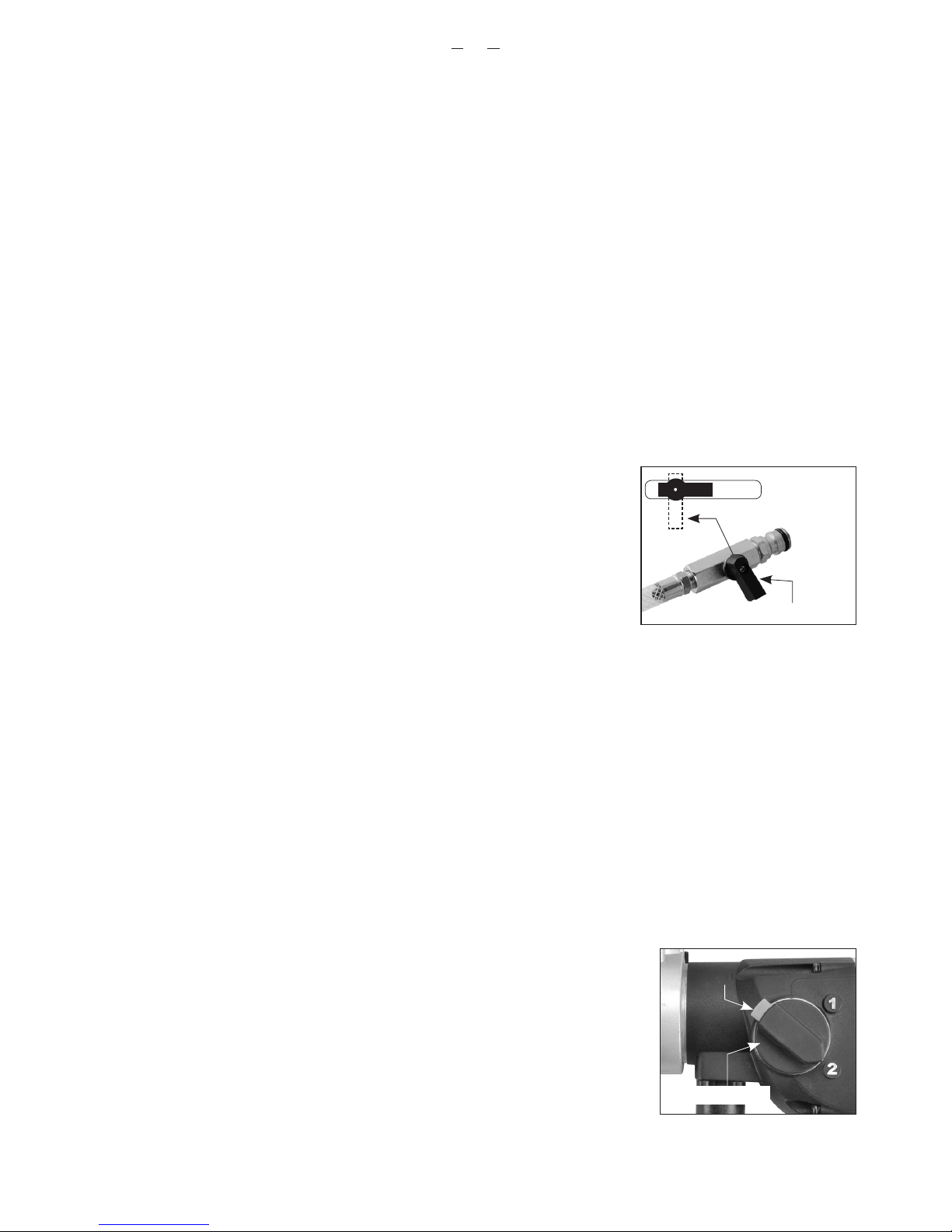
3. Make adjustments to the water feed as needed. The water leaving the cut should be a solid colored
slurry with about the consistency of milk.
4. Once in the cut, use steady feed pressure .
5. When breaking through, hold the machine tightly and reduce feed pressure .
WARNING: Always keep your face away from the machine.
The diamond impregnated segments in a wet type (sintered) diamond core bit operate on a principle of
controlled erosion. The bond matrix holding the diamonds is continually worn away by abrasion with the
work piece, exposing the harder diamonds to stand proud from the bond matrix.
Without adequate water, the bit would overheat and be destroyed.
With too much water and not enough feed pressure, there would not be adequate erosion of the bond
matrix and the bit becomes dull . This is called glazing . If the bit seems to refuse to cut anymore, it is
glazed. See below: ”SHARPENING A GLAZED BIT ”
Don’t feed too gently or the diamond segments will become glazed. Keep the bit steadily working.
If holding by hand, take great care to keep the bit aligned to the hole. If the bit is crooked, it will easily bind.
If the cut is very deep, the core plug may be obstructing the flow of cooling water. In this case, stop drilling, and
chisel out the core plug before continuing.
CAUTION: If the bit gets stuck, do not try to rock it loose by turning the switch on and off. That is
hazardous and could damage the motor. Rather, unplug the machine and use a wrench on the bit
mounting to work it loose.
If embedded steel such as rebar is encountered take special care. Reduce the feed pressure by about 1/3
and let the bit go at its own pace, if there is too much vibration the bit will be destroyed.
Once the steel is passed, continue normally.
CAUTION: Drilling operations are very stressful to the motor and at the end of the cut, the motor
temperature will be very hot, always run the motor at no load for a few minutes until the temperature
returns to a normal range before shutting off.
RESHARPENING A GLAZED BIT
If the bit becomes glazed, resharpen by dressing with an appropriate alumina oxide or silicon carbide dressing
stone. Simply drill into the stone as many times as necessary to restore its cutting performance.
VIBRATION TROUBLESHOOTING
If vibration occurs and it is not caused by embedded steel, stop drilling to find the cause and remedy.
CAUTION: Do not operate with vibration or there will be serious hazard and the diamond core bit
will surely be destroyed.

GB
10
Vibration is usually caused by:
1. A bit with too much runout
SOLUTION: Replace bit.
2. A bit with diamond segments broken off
SOLUTION: Repair or Replace bit.
MAINTENANCE
Every 50 hours of operation blow compressed air through the motor while running at no load to clean out
accumulated dust.
Always check for a damaged power supply cable, check for loose fasteners and always keep alert for
unusual noises and vibration when operating.
WARNING: Never operate a damaged machine. Always tag a damaged machine and take it out of
service until repairs can be made.
Maintenance which should be performed by an authorized service center, include the following:
• Replace water seals as needed.
• Replace the carbon brushes as needed
• Replace the clutch discs and spring as needed.
THE CARBON BRUSHES
The carbon brushes are a normal wearing part and must be replaced when they reach their wear limit. This
machine is equipped with auto-stop carbon brushes. If the machine comes to a stop unexpectedly, the brushes
should be checked. The auto-stop brush design protects the motor by stopping the machine before the carbon
brushes are completely worn out.
Caution: Always replace the brushes as a pair.
To replace:
1. Remove the 12 screws to open up the handle halves. Carefully move the parts to one side, taking care not
to strain the wiring.
2. Using pliers rotate the brush spring out of the way and slide the old carbon brush out of the brush
holder.
3. Unscrew the screw to remove the brush lead. The old carbon brush may now be lifted away.
4. Install a new brush. Installation is the reverse of removal.
5. Replace the motor tail cover.
If the replacement of the power supply cord is necessary, this has to be done by the manufacturer or
their agent in order to avoid a safety hazard.
WARNING: All repairs must be entrusted to an authorized service center. Incorrectly performed repairs
could lead to injury or death.
Do not throw electric power tools into the household waste!
In accordance with the European Directive 2012/19/EU on Waste Electrical and Electronic Equipment and
transposition into national law, used electric power tools must be collected separately and recycled in an
environmentally friendly manner.

11
GB
WIRING
1
2
1
2
AC
BRUSH
BRUSH
STATOR
BLACK
BLACK
BLACK
BLACK
BLACK
(TEMP. SENSOR)
ELECTRONICS UNIT
SWITCH
WHITE WHITE
TERMINAL CONNECTOR
BLOCK

GB
12
Exploded View
20
21
14
15
16
18
22
23
24
25
26
27
38
37
35
33 32
40
41
53
52
82
48
47
42
30
57
58
59
60
64
56
68
69
70
NO.01~83 Version 1.1
49
66
55
54
31
17 19
29 28 19
65
79
80
13
06
13
09
10
11
04 05
08
12
71
03
02
07
1A
1B
76
83

13
GB
Parts List
NO. Parts Name Q'TY
1A POWER SUPPLY CABLE VDE-1.0x3Cx1.4M-H07RNF 1
1B POWER SUPPLY CABLE NO PLUG-1.0x3Cx1.6M-H05VVF 1
2 PRCD INTERRUPTER PROTECTION 220V(RCD05) 1
3 CORD ARMOR 1
4 CABLE CLIP 1
5 PANHEAD TAPPING SCREW M4x14 2
6 SWITCH 12.5(12.5)A250V 22(22)A125V(110V&220V) 1
7 TERMINAL CONNECTOR BLOCK (PA-8-H)(17.5A) 1
8 ELECTRONICS UNIT 220V 1
9 HANDLE HALF-RIGHT 1
10 HANDLE HALF-LEFT 1
11 PANHEAD TAPPING SCREW M4x20 5
12 PANHEAD TAPPING SCREW M4x35 3
13 TORX PANHEAD TAPPING SCREW M5x20 4
14 PANHEAD TAPPING SCREW M4x8 4
15 BRUSH SPRING 0.4x4x3T 2
16 CARBON BRUSH HOLDER 7x17 2
17 INSULATION PLATE 10x38x1 2
18 CARBON BRUSH HOLDER 7x17x19 2
19 PANHEAD MACHINE SCREW M4x6 3
20 SPIRIT LEVEL 10x10x29 1
21 MOTOR HOUSING 1
22 STATOR 220V 1
23 PANHEAD TAPPING SCREW M5(3/16")x75(3") 2
24 FAN SHROUD 1
25 BALL BEARING 6200 1
26 ARMATURE 220V 1
27 BALL BEARING 6201 1
28 EXTERNAL STAR WASHER M4 1
29 EARTH WIRE 1
30 GEAR PLATE 1
31 GASKET 1
32 BALL BEARING 608 1
33 CLUTCH NUT M10xP1.25x 17x 8.1 1
34 N/A -
35 PRESSURE DISC Ø12.1xØ28x2.65 1
36 N/A -
NO. Parts Name Q'TY
37 INPUT GEAR M1.0 x 34T 1
38 BUSHING Ø12xØ18x4.2 1
39 N/A -
40 INPUT SHAFT M1.25 x 17T ; M1.25 x 11T 1
41 NEEDLE BEARING HK 0810 1
42 NEEDLE BEARING HK 1010 1
43~46 N/A -
47 SLIDER GEAR-AB M1.25 x 38T ; M1.25 x 44T 1
48 GEAR HOUSING 1
49 FLAT HEAD SOCKET CAP SCREW M5 x 16 1
50~51 N/A -
52 O-RING Ø20 x 3 1
53 GEAR SELECTOR 1
54 SPRING Ø0.6xØ3.8xØ5x11Tx35L 1
55 RELEASE PIN 1
56 TORX PANHEAD TAPPING SCREW M5x60 4
57 OIL SEAL Ø27 x Ø42 x 7 1
58 OIL SEAL Ø27 x Ø45 x 8 1
59 INTERNAL CIRCLIP IS28 1
60 BALL BEARING 60/28 1
61~63 N/A -
64 PARALLEL KEY 5x5x45 1
65 SPINDLE 1-1/4"-7x1/2"BSP-202MM 1
66 INTERNAL CIRCLIP R-52 1
67 N/A -
68 HANDLE CLAMP 1
69 SPACER Ø6.1xØ12x10 1
70 THUMB SCREW M6x55 1
71 FRONT HANDLE M12 1
72~75 N/A -
76 WATER FEED CONNECTOR KIT 1
77~78 N/A 1
79 CLUTCH DISC SET 1
80 O-RINGØ31.5 x 1.5 1
81 N/A -
82 SELECTOR DISC 1
83 STAINLESS BUSHING Ø25xØ27x9 1

GB
14
Noise/vibration information
Measured in accordance with EN 60745-2-1
Model no. : DM5
Noise level: LpA: 94.0 db(A) LwA: 105.0 db(A) K=3.0 db(A)
Vibration level: ah= 10.1 m/s2K = 1.5 m/s2
The vibration emission level has been measured in accordance with a standardised test given in EN 60745; it
may be used to compare one tool with another and as a preliminary assessment of exposure to vibration when
using the tool for the applications mentioned
- using the tool for dierent applications, or with dierent or poorly maintained accessories,
may signicantly increase the exposure level - the times when the tool is switched o or when it is running but
not actually doing the job, may signicantly reduce the exposure level
! protect yourself against the effects of vibration by maintaining the tool and its accessories, keeping your
hands warm, and organizing your work patterns
CE Declaration of Conformity
•We declare under our sole responsibility that this product is in conformity with the following
standards or standardized documents: EN 60745-1:2009+A11:2010 & EN 60745-2-1:2010; in EN
55014-1:2006+A1:2009+A2:2011; EN55014-2:1997+A1:2001+A2:2008; EN 61000-3-2:2014; EN61000-3-3:2013 in
accordance with the regulations 2014/30/EU, 2006/42/EC, 2011/65/EU
•Technical le at: LEE YEONG INDUSTRIAL CO., LTD., NO.2, KEJIA RD., DOULIU CITY,
YUNLIN COUNTY 64057, TAIWAN
LEE YEONG INDUSTRIAL CO., LTD.
NO.2, KEJIA RD., DOULIU CITY,
YUNLIN COUNTY 64057, TAIWAN
TEL: 886-5-5518689 (REP)
Fax: 886-5-5518635
You-Chun, Liu
Operation & Engineering
Chih-Hao, Lai
Approval Manager
LEE YEONG INDUSTRIAL CO., LTD.,
NO.2, KEJIA RD., DOULIU CITY, YUNLIN COUNTY 64057, TAIWAN 12.27.2016

D
15
1. Motor
2. Wasserwaage
3. Gangwahlschalter
4. Entriegelungstaste
5. Klemmschraube (Seitengri)
6. Spindel
Modell DM5
Leistungsaufnahme 1800 W
Spannung 110-120 V~ 50-60 Hz, 220-240 V~ 50-60 Hz (Siehe Typenschild)
Leerlauf/Volllast min-1 Gang 1 1300 / 720
Gang 2 2300 / 1260
Kapazität-Nass 132mm (5-1/4")
Werkzeugaufnahme 1-1/4"UNC & 1/2" BSP
Halsdurchmesser 60 mm
Schutzklasse Klasse I mit FI-Schalter
Abmessungen (mm) 450 mm x 105 mm x 280 mm
Nettogewicht 4,9 kg (10,8 lbs)
TECHNISCHE DATEN:
7.
1.
2.
3.
4.
5.
6.
8.
9.
10.
11.
12.
7. Wasserzufuhrventil
8. Seitengri
9. Druckschalter
10. Feststelltaste
11. Hauptgri
12. Netzkabel

D
16
Allgemeine Sicherheitshinweise
ACHTUNG! Lesen Sie sämtliche Sicherheitshinweise und Anweisungen. Fehler bei der Einhaltung
der Warnhinweise und Anweisungen können elektrischen Schlag, Brand und/oder schwere
Verletzungen verursachen.
Bewahren Sie alle Sicherheitshinweise und Anweisungen für die Zukunft auf.
Der in den Sicherheitshinweisen verwendete Begri„Elektrowerkzeug“ bezieht sich auf netzbetriebene
Elektrowerkzeuge (mit Netzkabel) und auf akkubetriebene Elektrowerkzeuge (ohne Netzkabel).
1. ARBEITSPLATZSICHERHEIT
a. Halten Sie Ihren Arbeitsbereich sauber und aufgeräumt. Unordnung und unbeleuchtete
Arbeitsbereiche können zu Unfällen führen.
b. Arbeiten Sie mit dem Gerät nicht in explosionsgefährdeter Umgebung, in der sich brennbare
Flüssigkeiten, Gase oder Stäube be nden. Elektrowerkzeuge erzeugen Funken, die den Staub oder die
Dämpfe entzünden können.
c. Halten Sie Kinder und andere Personen während der Benutzung des Elektrowerkzeugs fern. Bei
Ablenkung können Sie die Kontrolle über das Gerät verlieren.
d. Lassen Sie das Elektrowerkzeug nicht unbeaufsichtigt laufen. Verlassen Sie das Elektrowerkzeug erst,
wenn das Einsatzwerkzeug komplett zum Stillstand gekommen ist.
2. ELEKTRISCHE SICHERHEIT
a. Der Anschlussstecker des Gerätes muss in die Steckdose passen. Der Stecker darf in keiner Weise
verändert werden. Verwenden Sie keine Adapterstecker gemeinsam mit schutz geerdeten Geräten.
Unveränderte Stecker und passende Steckdosen verringern das Risiko eines elektrischen Schlages.
b. Vermeiden Sie Körperkontakt mit geerdeten Ober ächen, wie von Rohren, Heizungen, Herden
und Kühl schränken. Es besteht ein erhöhtes Risiko durch elektrischen Schlag, wenn Ihr Körper geerdet
ist.
c. Halten Sie das Gerät von Regen oder Nässe fern. Das Eindringen von Wasser in ein Elektrogerät erhöht
das Risiko eines elektrischen Schlages.
d. Zweckentfremden Sie das Kabel nicht, um das Gerät zu tragen, aufzuhängen oder um den Stecker
aus der Steckdose zu ziehen. Halten Sie das Kabel fern von Hitze, Öl, scharfen Kanten oder sich
bewegenden Geräteteilen. Beschädigte oder verwickelte Kabel erhöhen das Risiko eines elektrischen
Schlages.
e. Wenn Sie mit einem Elektrowerkzeug im Freien arbeiten, verwenden Sie nur Verlängerungskabel,
die auch für den Außenbereich zugelassen sind. Die Anwendung eines für den Außenbereich
geeigneten Verlängerungskabels verringert das Risiko eines elektrischen Schlages.
f. Wenn der Betrieb des Elektrowerkzeuges in feuchter Umgebung nicht vermeidbar ist, verwenden

D
17
Sie einen Fehlerstromschutzschalter. Der Einsatz eines Fehlerstromschutzschalters vermindert das
Risiko eines elektrischen Schlages.
3. SICHERHEIT VON PERSONEN
a. Seien Sie aufmerksam, achten Sie darauf, was Sie tun, und gehen Sie mit Vernunft an die Arbeit mit
einem Elektrowerkzeug. Benutzen Sie das Gerät nicht, wenn Sie müde sind oder unter dem Ein
uss von Drogen, Alkohol oder Medikamenten stehen. Ein Moment der Unachtsamkeit beim Gebrauch
des Gerätes kann zu ernsthaften Verletzungen führen.
b. Tragen Sie persönliche Schutzausrüstung und immer eine Schutzbrille. Das Tragen persönlicher
Schutzausrüstung, wie Staubmaske, rutschfeste Sicherheitsschuhe, Schutzhelm oder Gehörschutz, je
nach Art und Einsatz des Elektrowerkzeuges, verringert das Risiko von Verletzungen.
c. Vermeiden Sie eine unbeabsichtigte Inbetriebnahme. Vergewissern Sie sich, dass der Schalter in
der Position“AUS”ist, bevor Sie den Stecker in die Steckdose stecken. Wenn Sie beim Tragen des
Geräts den Finger am Schalter haben oder das Gerät eingeschaltet an die Stromversorgung anschließen,
kann dies zu Unfällen führen.
d. Entfernen Sie Einstellwerkzeuge oder Schraubenschlüssel, bevor Sie das Gerät einschalten. Ein
Werkzeug oder Schlüssel, der sich in einem drehenden Geräteteil be ndet, kann zu Verletzungen führen.
e. Überschätzen Sie sich nicht. Sorgen Sie für einen sicheren Stand und halten Sie jederzeit das
Gleichgewicht. Dadurch können Sie das Gerät in unerwarteten Situationen besser kontrollieren.
f. Tragen Sie geeignete Kleidung. Tragen Sie keine weite Kleidung oder Schmuck. Halten Sie Haare
und Kleidung fern von sich bewegenden Teilen. Lockere Kleidung, Schmuck oder lange Haare können
von sich bewegenden Teilen erfasst werden.
g. Wenn Staubabsaug- und -auangeinrichtungen montiert werden können, vergewissern Sie sich,
dass diese angeschlossen sind und richtig verwendet werden. Das Verwenden dieser Einrichtungen
verringert Gefährdungen durch Staub.
h. Lassen Sie nicht zu, dass Sie durch Gewohnheit, die durch häu gen Gebrauch der Geräte
erlangt wurde, selbstzufrieden werden und die grundlegenden Sicherheitsprinzipien des Geräts
mißachten. Eine unvorsichtige Tätigkeit kann schwere Verletzung innerhalb Sekundenbruchteils
verursachen.
4. SORGFÄLTIGER UMGANG UND GEBRAUCH VON ELEKTROWERKZEUGEN
a. Überlasten Sie das Gerät nicht. Verwenden Sie für Ihre Arbeit das dafür bestimmte Elektrowerkzeug.
Mit dem passenden Elektrowerkzeug arbeiten Sie besser und sicherer im angegebenen Leistungsbereich.
b. Benutzen Sie kein Elektrowerkzeug, dessen Schalter defekt ist. Ein Elektrowerkzeug, das sich nicht
mehr ein- oder ausschalten lässt, ist gefährlich und muss repariert werden.
c. Ziehen Sie den Stecker aus der Steckdose, bevor Sie Geräteeinstellungen vornehmen, Zubehörteile
wechseln oder das Gerät weglegen. Diese Vorsichtsmaßnahme verhindert den unbeabsichtigten Start
des Geräts.
d. Bewahren Sie unbenutzte Elektrowerkzeuge außerhalb der Reichweite von Kindern auf. Lassen Sie

D
18
Personen das Gerät nicht benutzen, die mit diesem nicht vertraut sind oder diese Anweisungen
nicht gelesen haben. Elektrowerkzeuge sind gefährlich, wenn Sie von unerfahrenen Personen benutzt
werden.
e. P egen Sie das Gerät mit Sorgfalt. Kontrollieren Sie, ob bewegliche Geräteteile einwandfrei
funktionieren und nicht klemmen, ob Teile gebrochen oder so beschädigt sind, dass die Funktion
des Gerätes beeinträchtigt ist. Lassen Sie beschädigte Teile vor dem Einsatz des Geräts reparieren.
Viele Unfälle haben ihre Ursache in schlecht gewarteten Elektrowerkzeugen.
f. Halten Sie Schneidwerkzeuge scharf und sauber. Sorgfältig gep egte Schneidwerkzeuge mit scharfen
Schneidkanten verklemmen sich weniger und sind leichter zu führen.
g. Verwenden Sie Elektrowerkzeug, Zubehör, Einsatzwerkzeuge usw. entsprechend diesen
Anweisungen und so, wie es für diesen speziellen Gerätetyp vorgeschrieben ist. Berücksichtigen
Sie dabei die Arbeitsbedingungen und die auszuführende Tätigkeit. Der Gebrauch von
Elektrowerkzeugen für andere als die vorgesehenen Anwendungen kann zu gefährlichen Situationen
führen.
h. Halten Sie Handgrie trocken, sauber und frei von Öl und Fett. Rutschige Handgrie erlauben keine
sichere Handhabung und Kontrolle des Elektrowerkzeuges in unerwarteter Situation.
5. SERVICE
a. Lassen Sie Ihr Gerät nur von quali ziertem Fachpersonal und nur mit Original-Ersatzteilen
reparieren. Damit wird sichergestellt, dass die Sicherheit des Geräts erhalten bleibt.
b. Verwenden Sie für Reparatur und Wartung nur originale Teile. Die Verwendung von nicht dafür
vorgesehenem Zubehör oder Ersatzteilen kann zu elektrischem Schlag oder zu Verletzungen führen.
V…….........Volt
A……..........Ampere
Hz.................Hertz
W…….........Watt
~……….....Wechselstrom
n0………....Leerlaufdrehzahl
min-1….......Umdrehungen oder
Zyklenzahl pro Minute
.........Warnung vor allgemeiner Gefahr
....…mit Schutzleiter
.......Diese Betriebsanleitung lesen
......Stets Augenschutz tragen
......Stets eine Atemschutzmaske tragen
.... Stets Gehörschutz tragen
..... Schutzhelm tragen
Elektrowerkzeuge, Zubehör und Verpackung
dürfen nicht mit dem Hausmüll entsorgt werden.
In dieser Betriebsanleitung verwendete Symbole

D
19
SICHERHEITSHINWEISE FÜR BOHRMASCHINEN
• Zusatzhandgri(e) verwenden. Der Verlust der Kontrolle über die Maschine kann zu Verletzungen führen.
• Halten Sie die Maschine an den isolierten Griächen, wenn Sie Arbeiten ausführen, bei denen das
Einsatzwerkzeug verborgene Stromleitungen oder das eigene Netzkabel treen kann. Der Kontakt mit einer
spannungsführenden Leitung kann auch metallene Maschinenteile unter Spannung setzen und zu einem elektrischen
Schlag führen.
• Verwenden Sie die Maschine niemals ohne den mitgelieferten Fehlerstromschutzschalter.
• Überprüfen Sie den Fehlerstromschutzschalter stets auf korrekte Funktion, bevor Sie die Bohrmaschine
verwenden.
• Stellen Sie sicher, dass während des Betriebs kein Wasser in die Motoreinheit gelangt.
• Wenn Sie an einem Teil des Wasserzufuhrsystems eine Undichtigkeit entdecken, schalten Sie die Maschine sofort
ab und beheben Sie die Störung. Der Wasserdruck sollte 70 psi (4 bar) nicht überschreiten.
• Sperren Sie den Arbeitsbereich ab und stellen Sie Warnschilder auf beiden Seiten der Wand auf, wenn Sie eine
Wand durchbohren.
• Treen Sie geeignete Vorkehrungen dafür, sicherzustellen, dass im Falle, dass ein Bohrkern herausfällt, dies zu
keinen Verletzungen oder Sachschäden führt.
• Wenn Sie hohle Bauteile bohren, prüfen Sie die Flussroute des Kühlwassers, um Schäden zu vermeiden.
EINLEITUNG
Die Maschine ist mit Wasserwaagen zur Hilfe bei der Ausrichtung des Werkzeugs ausgestattet. Benutzen Sie die Dosenlibelle
für die vertikale Ausrichtung und die Röhrenlibelle für die horizontale Ausrichtung.
Diese Maschine ist für den vorgesehenen Zweck des Diamant-Kernbohrens in Beton, Mauerwerk, Stein und ähnlichen
Materialien konzipiert. Die Maschine kann beim Bohren bis zu 80 mm von Hand gehalten werden. Für Größen über 80 mm
muss sie an einem Bohrständer montiert sein. Der Ständer ist nicht im Lieferumfang enthalten.
Alle anderen Verwendungen, die nicht dem vorgesehenen Zweck entsprechen, sind verboten.
Die Maschine ist mit einem Wasserzufuhrsystem ausgestattet, dass für das Diamant-Kernbohren erforderlich ist.
Sie ist mit einer tragbaren Fehlerstrom-Schutzeinrichtung (PRCD) ausgestattet, die jederzeit benutzt werden muss. Sie ist
mit einem mechanischen 2-Gang-Getriebe für verschiedene Kernbohrgrößenbereiche ausgestattet und verfügt über eine
mechanische Sicherheitskupplung.
Der Motor hat eine Elektronik für Sanftanlauf, Überlast- und Überhitzungsschutz.
ELEKTROANSCHLUSS
Die Netzspannung muss mit der Spannungsangabe auf dem Typenschild des Werkzeugs übereinstimmen.
Das Werkzeug darf unter keinen Umständen verwendet werden, wenn das Netzkabel beschädigt ist. Ein beschädigtes Kabel
muss sofort durch ein autorisiertes Service Center ersetzt werden. Versuchen Sie nicht, das beschädigte Kabel selbst zu
reparieren. Die Verwendung von beschädigten Kabeln kann zu einem elektrischen Schlag führen.
WARNUNG:
Diese Maschine ist mit einer tragbaren Fehlerstrom-Schutzeinrichtung (PRCD), auch bekannt als
Fehlerstromschutzschalter (FI-Schalter) ausgestattet. Verwenden Sie dieses Gerät stets bei Benutzung der Maschine,
um die Gefahr von Stromschlägen zu reduzieren. Testen Sie den FI-Schalter vor jedem Gebrauch und stellen Sie ihn
zurück. Drücken Sie die Taste„Test“, um zu testen. Drücken Sie die Taste„Zurücksetzen“, um die Maschine mit Strom zu

D
20
versorgen.
WARNUNG!: Die 110 V-Maschinen für Großbritannien sind nicht
mit einer tragbare Fehlerstrom-Schutzeinrichtung bzw. einem
Fehlerstromschutzschalter ausgestattet. Die Maschine muss immer mit
einem Trenntransformator als Schutz im Falle einer elektrischen Störung
verwendet werden.
Verwenden Sie einen Fehlerstromschutzschalter in einem separaten
Schaltkasten mit einer oder mehrere Steckdosen in Übereinstimmung mit EN 60309-2 mit Schutzleiterposition 1h.
MONTAGE
1. Bauen Sie die Schelle des Seitengris an den Getriebehals an. Positionieren Sie den seitlichen Gri senkrecht an den
Hauptgri. Verwenden Sie die Klemmschraube zum Festziehen der Schelle.
2. Schrauben Sie die Wasserzufuhrbaugruppe in die Önung an der Unterseite des Getriebes, und ziehen Sie sie mit einem
Schraubenschlüssel fest.
INHALT
• Diamant-Kernbohrmaschine
• Seitengribaugruppe
• Wasserzufuhrbaugruppe
• Schraubenschlüssel
BEDIENUNGSANLEITUNG
1) ANBAU DER BOHRKRONE
ACHTUNG: Vergewissern Sie sich, dass die Gewinde der Spindel und der Bohrkrone übereinstimmen. Beim Versuch,
nicht übereinstimmende Gewinde zu verbinden, kommt es zu Beschädigungen beider Gewinde.
Die Spindel hat zwei Arten von Gewinden. Das Außengewinde ist 1-1/4 Zoll UNC, das Innengewinde ist 1/2 Zoll BSP.
Stellen Sie sicher, dass sowohl die Bohrkrone als auch die Spindel sauber sind. Verschmutzungen können zu einem
übermäßigen Seitenschlag der angebauten Bohrkrone führen. Ein übermäßiger Seitenschlag kann zu einem vorzeitigen Ausfall
der Bohrkrone führen und/oder eine Gefahrenquelle darstellen.
Ziehen Sie die Bohrkrone auf der Spindel mit Hilfe von zwei Schlüsseln fest.
Auswahl der richtigen Bohrkrone
Stellen Sie sicher, dass die Bohrkrone, die Sie verwenden, für die Materialien, die Sie bohren, geeignet ist. Es gibt zwei
Haupttypen von Diamantbohrkronen:
-Nassbohrkronen (Nassbohrkronen müssen immer mit Wasser verwendet werden)
-Trockenbohrkronen
Test-Taste
Zurücksetzen-Taste
Betriebsanzeig
Table of contents
Languages:
Other AGP Drill manuals
Popular Drill manuals by other brands

Black & Decker
Black & Decker Fire Storm 626484-00 instruction manual

Skil
Skil 2320 Origiman instructions

GÜDE
GÜDE GTB 16 LASER/550 W Translation of the original instructions

Proxxon
Proxxon IBS/E manual

Bosch
Bosch GBH Professional 3-28 DRE Original instructions

Parkside
Parkside PTB-16 Operation and safety notes