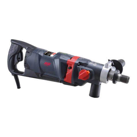
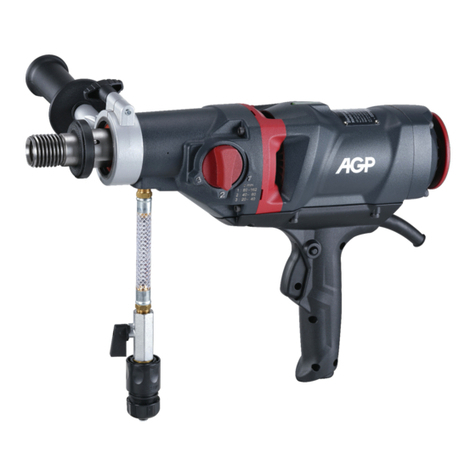
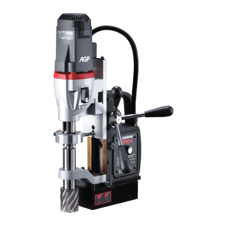
AGP MD120/4 User manual

1
ORIGINAL OPERATING INSTRUCTIONS
SAVE THESE INSTRUCTIONS FOR FUTURE REFERENCE.
Warning:
For tools equipped with over load protection, when motor has shut down o due to over
load, always run machine with no load for at least 3 minutes to reduce temperature before
returning to operation to avoid burn out of the motor.
1 Speed Drilling System
1 Speed Drilling System (N)
Semi Auto Feed Drilling System
Semi Auto Feed Drilling System(N)
2 Speed Drilling System
4 Speed Drilling System
4 Speed Swivel Base Drilling System
4 Speed Variable Motor Speed
Drilling System

2
Coolant tank
Motor switch
Magnet switch
Coolant feed tap
Arbor
Arbor support bracket
Annular cutter
(Not included)
Pilot pin (Not included)
Magnet base
Gib adjustor screw
Optional adaptor and
13mm chuck (Not included)
1 Speed Drilling System & 1 Speed Drilling System (N)
STANDARD ACCESSORIES
* WRENCH M8
* HEX. KEY M2.5
* HEX. KEY M4
* CHIP GUARD KIT
* COOLANT TANK KIT
* SAFETY CHAIN
OPTIONAL ACCESSORY
* CHUCK ADAPTOR
* 13MM CHUCK & KEY
MODEL 1 Speed 1 Speed(N)
POWER INPUT 9.5A
VOLTAGE 115V, 60Hz
NO / FULL LOAD min-1 620/350 550/330
DIA. X DEPTH OF CUT 35MM X 50MM
CAPACITY DIA. X DEPTH OF TWIST DRILL BIT 13MM X 110MM
DIA. X DEPTH OF TAPS NA
MAGNETIC ADHESION 15,000 N
NET WEIGHT 12.6 kg (27.72 Lbs )

3
Dual purpose lever
Crank handle
Arbor
Arbor support
bracket
Annular cutter
(Not included)
Pilot pin
(Not included)
Coolant tank
Motor switch
Magnet switch
Coolant feed tap
Magnet base
3 position feed
rate selector
Semi Auto Feed Drilling System & Semi Auto Feed Drilling System (N)
STANDARD ACCESSORIES
* WRENCH M8
* HEX. KEY M2.5
* HEX. KEY M4
* CHIP GUARD KIT
* COOLANT TANK KIT
* SAFETY CHAIN
MODEL Semi Auto Feed Semi Auto Feed (N)
POWER INPUT 1100 W
VOLTAGE See machine nameplate
NO / FULL LOAD min-1 620/350 550 / 330
DIA. X DEPTH OF CUT ( HAND FEED)
35MM X 50MM
CAPACITY
DIA. X DEPTH OF CUT ( AUTO FEED)
30MM X 45MM
DIA. X DEPTH OF TWIST DRILL BIT ( HAND FEED ONLY)
13MM X 110MM
DIA. X DEPTH OF TAPS
NA
MAGNETIC ADHESION 15,000 N
NET WEIGHT 16.5 kg (36.3 Lbs )

4
Arbor
Arbor support
bracket
Gear selector
Coolant tank
Motor switch
Magnet switch
Coolant feed tap
Magnet base
Annular cutter
(Not included)
Pilot pin
(Not included)
Optional adaptor and
16mm chuck (Not included)
2 Speed Drilling System
MODEL 2 Speed
POWER INPUT 1700 W (110V), 2000W (220V)
VOLTAGE
See machine nameplate
NO/FULL LOAD min-1 SPEED 1 380 / 230
SPEED 2 550 / 330
DIA. X DEPTH OF CUT 65 MM X 75 MM (2"X3")
CAPACITY: DIA. X DEPTH OF TWIST DRILL BIT 16MM X 115 MM (5/8" X 4-1/2")
DIA. X DEPTH OF TAPS NA
MAGNETIC ADHESION 32,000 N
NET WEIGHT 22.9 KG (50.38 LBS)
STANDARD ACCESSORIES
* WRENCH M8
* HEX. KEY M2.5
* HEX. KEY M4
* CHIP GUARD KIT
* COOLANT TANK KIT
* SAFETY CHAIN
OPTIONAL ACCESSORY
* CHUCK ADAPTOR
* 16MM CHUCK & KEY

5
Magnet base
Coolant tank
Motor switch
Magnet switch
Coolant feed tap
Reversing switch
Arbor
Arbor support bracket
Annular cutter
(Not included)
Gear selector
Ejector port
Pilot pin (Not included)
MT3 Twist drill bit
(Not included)
MT3 Chuck adaptor
and Chuck
(Not included)
MT3 Tapping adaptor
and Tapping unit
(Not included)
4 Speed Drilling System
STANDARD ACCESSORIES
* WRENCH M8
* HEX. KEY M2.5
* HEX. KEY M4
* CHIP GUARD KIT
* COOLANT TANK KIT
* SAFETY CHAIN
* DRIFFT
OPTIONAL ACCESSORY
* MT3 CHUCK ADAPTOR
* 16MM CHUCK & KEY
* MT3 TAPPING ADAPTOR
* TAPPING ATTACHMENT
POWER INPUT 1700 W (110V), 2000W (220V)
VOLTAGE See machine nameplate
SPEED 1 150 / 90
NO/FULL LOAD min-1 SPEED 2 200 / 120
SPEED 3 300 / 180
SPEED 4 380 / 230
DIA. X DEPTH OF CUT ( HAND FEED) 75MM X 50MM
CAPACITY DIA. X DEPTH OF MT3TWIST DRILL BIT 32MM X 150MM
DIA. X DEPTH OF MT3 CHUCK ADAPTORWITH TWIST DRILL BIT 16MM X 110MM
DIA. X DEPTH OF TAPS 25.4MM X 40MM
MAGNETIC ADHESION 32,000N
NET WEIGHT 24.8 kg ( 54.56 Lbs)

6
Magnet base
Coolant tank
Motor switch
Magnet switch
Coolant feed tap
Reversing switch
Crank handle
Arbor
Arbor support bracket
Annular cutter(Not included)
Gear selector
Ejector port
Pilot pin (Not included)
MT3 Twist drill bit
(Not included)
MT3 Chuck adaptor
and Chuck
(Not included)
MT3 Tapping adaptor
and Tapping unit
(Not included)
4 Speed Swivel Base Drilling System
30°,2x15° 20mm
STANDARD ACCESSORIES
* WRENCH M8
* HEX. KEY M2.5
* HEX. KEY M4
* CHIP GUARD KIT
* COOLANT TANK KIT
* SAFETY CHAIN
* DRIFFT
OPTIONAL ACCESSORY
* MT3 CHUCK ADAPTOR
* 16MM CHUCK & KEY
* MT3 TAPPING ADAPTOR
* TAPPING ATTACHMENT
POWER INPUT 1700 W (110V), 2000W (220V)
VOLTAGE See machine nameplate
SPEED 1 150 / 90
NO/FULL LOAD min-1 SPEED 2 200 / 120
SPEED 3 300 / 180
SPEED 4 380 / 230
DIA. X DEPTH OF CUT ( HAND FEED) 75MM X 50MM
CAPACITY DIA. X DEPTH OF MT3TWIST DRILL BIT 32MM X 150MM
DIA. X DEPTH OF MT3 CHUCK ADAPTORWITH TWIST DRILL BIT 16MM X 110MM
DIA. X DEPTH OF TAPS 25.4MM X 40MM
MAGNETIC ADHESION 32,000N
NET WEIGHT 27 kg ( 59.4 Lbs)

7
4 Speed Variable Motor Speed Drilling System
Magnet base
Coolant tank
Motor switch
Magnet switch
Coolant feed tap
Reversing switch Spindle
Annular cutter
(Not included)
Gear selector
Ejector port
Pilot pin
(Not included)
1-1/4 " (32.7mm) Weldon shank
annular cutter arbor
MT3 Twist drill bit
(Not included)
MT3 Tapping adaptor and
Tapping unit
(Not included)
MT3 Chuck adaptor
and Chuck
(Not included)
Variable Speed Wheel
* Max. Dia. x Depth of cut with Annular Cutters with 19mm Weldon or Quick-Release Arbor: 60mm x 50mm ( 2-3/8" x 2")
Standard Accessories
* WRENCH M8
* HEX. KEY M2.5 & M5
* CHIP GUARD KIT
* COOLANT TANK KIT
* SAFETY CHAIN
* DRIFT
POWER INPUT 1700 W (110V), 2000W (220V)
VOLTAGE See machine nameplate
SPEED 1 35 - 120
NO/FULL LOAD min-1 SPEED 2 70 - 220
SPEED 3 80 - 250
SPEED 4 140 - 450
Dia. X Depth of cut with Annular Cutters 120mm x 50mm (4-3/4" x 2")
CAPACITY Dia. X Depth of MT3Twist Drill Bit 32mm x 150mm ( 1-1/4" x 6" )
Dia. X Depth of MT3 Chuck adaptor withTwist Drill bit 16mm x 110mm (5/8" x 4-5/16")
Dia. X Depth of Taps 25.4mm x 40mm (1" x 1-9/16")
MAGNETIC ADHESION 32,000N
Overload Protection Standard
NET WEIGHT 27 kg ( 59.4 Lbs)

8
General power tool safety warnings
WARNING Read all safety warnings, instructions, illustrations and specifications provided
with this power tool. Failure to follow all instructions listed below may result in electric shock,
fire and/or serious injury.
Save all warnings and instructions for future reference.
The term "power tool" in the warnings refers to your mains-operated (corded) power tool or battery-
operated (cordless) power tool.
1) Work area safety
a. Keep work area clean and well lit. Cluttered or dark areas invite accidents.
b. Do not operate power tools in explosive atmospheres, such as in the presence of flammable
liquids, gases or dust. Power tools create sparks which may ignite the dust or fumes.
c. Keep children and bystanders away while operating a power tool. Distractions can cause you to lose
control.
2) Electrical safety
a. Power tool plugs must match the outlet. Never modify the plug in any way. Do not use any adapter
plugs with earthed (grounded) power tools. Unmodified plugs and matching outlets will reduce risk
of electric shock.
b. Avoid body contact with earthed or grounded surfaces, such as pipes, radiators, ranges and
refrigerators. There is an increased risk of electric shock if your body is earthed or grounded.
c. Do not expose power tools to rain or wet conditions. Water entering a power tool will increase
the risk of electric shock.
d. Do not abuse the cord. Never use the cord for carrying, pulling or unplugging the power tool. Keep
cord away from heat, oil, sharp edges or moving parts. Damaged or entangled cords increase the risk
of electric shock.
e. When operating a power tool outdoors, use an extension cord suitable for outdoor use. Use of
a cord suitable for outdoor use reduces the risk of electric shock.
f. If operating a power tool in a damp location is unavoidable, use a residual current device (RCD)
protected supply. Use of an RCD reduces the risk of electric shock.
3) Personal safety
a. Stay alert, watch what you are doing and use common sense when operating a power tool.
Do not use a power tool while you are tired or under the influence of drugs, alcohol or medication.
A moment of inattention while operating power tools may result in serious personal injury.
b. Use personal protective equipment. Always wear eye protection. Protective equipment such as a
dust mask, non-skid safety shoes, hard hat or hearing protection used for appropriate conditions will
reduce personal injuries.
c. Prevent unintentional starting. Ensure the switch is in the off-position before connecting to power
source and/or battery pack, picking up or carrying the tool. Carrying power tools with your finger on
the switch or energising power tools that have the switch on invites accidents.
d. Remove any adjusting key or wrench before turning the power tool on. A wrench or a key left

9
attached to a rotating part of the power tool may result in personal injury.
e. Do not overreach. Keep proper footing and balance at all times. This enables better control of the
power tool in unexpected situations.
f. Dress properly. Do not wear loose clothing or jewellery. Keep your hair and clothing away from
moving parts. Loose clothes, jewellery or long hair can be caught in moving parts.
g. If devices are provided for the connection of dust extraction and collection facilities, ensure
these are connected and properly used. Use of dust collection can reduce dust-related hazards.
h. Do not let familiarity gained from frequent use of tools allow you to become complacent
and ignore tool safety principles. A careless action can cause severe injury within a fraction of a
second.
4) Power tool use and care
a. Do not force the power tool. Use the correct power tool for your application. The correct power tool
will do the job better and safer at the rate for which it was designed.
b. Do not use the power tool if the switch does not turn it on and off. Any power tool that cannot be
controlled with the switch is dangerous and must be repaired.
c. Disconnect the plug from the power source and/or remove the battery pack, if detachable,
from the power tool before making any adjustments, changing accessories, or storing power
tools. Such preventive safety measures reduce the risk of starting the power tool accidentally.
d. Store idle power tools out of the reach of children and do not allow persons unfamiliar with
the power tool or these instructions to operate the power tool. Power tools are dangerous in the
hands of untrained users.
e. Maintain power tools and accessories. Check for misalignment or binding of moving parts,
breakage of parts and any other condition that may affect the power tool’s operation. If
damaged, have the power tool repaired before use. Many accidents are caused by poorly maintained
power tools.
f. Keep cutting tools sharp and clean. Properly maintained cutting tools with sharp cutting edges are
less likely to bind and are easier to control.
g. Use the power tool, accessories and tool bits etc. in accordance with these instructions, taking
into account the working conditions and the work to be performed. Use of the power tool for
operations different from those intended could result in a hazardous situation.
h. Keep handles and grasping surfaces dry, clean and free from oil and grease. Slippery handles
and grasping surfaces do not allow for safe handling and control of the tool in unexpected situations.
5) Service
Have your power tool serviced by a qualified repair person using only identical replacement parts. This
will ensure that the safety of the power tool is maintained.
TERMINOLOGY USED IN THE MANUAL
1. Warning: This term means that there is a risk of physical harm or death to the operator or people
nearby.
2. Caution: This term means that there is a risk of damage to the machine, cutting tool or other
equipment.
3. Note: These terms offer useful information relating to the operation of the machine or its
maintenance.

10
DRILL SAFETY WARNINGS
a. The drill must be secured. A drill that is not properly secured may move or tip over and may result in
personal injury.
b. The workpiece must be clamped or secured to the workpiece support. Do not drill pieces that are
too small to be clamped securely. Holding the workpiece by hand during operation may result in
personal injury.
c. Do not wear gloves. Gloves may be entangled by the rotating parts or chips, leading to personal injury.
d. Keep your hands out of the drilling area while the tool is running. Contact with rotating parts or
chips may result in personal injury.
e. Make sure the accessory is rotating before feeding into the workpiece. Otherwise the accessory may
become jammed in the workpiece, causing unexpected movement of the workpiece and personal injury.
f. When the accessory is jammed, stop applying downward pressure and switch off the tool.
Investigate and take corrective actions to eliminate the cause of the jam. Jamming can cause
unexpected movement of the workpiece and personal injury.
g. Avoid generating long chips by regularly interrupting downward pressure. Sharp metal chips may
cause entanglement and personal injuries.
h. Never remove chips from the drilling area while the tool is running. To remove chips, move the
accessory away from the workpiece, switch off the tool, and wait for the accessory to stop moving.
Use tools such as a brush or hook to remove chips. Contact with rotating parts or chips may result in
personal injury.
i. Accessories with speed ratings must be rated at least equal to the maximum speed marked on the
power tool. Accessories running faster than their rated speed can break and fly apart.
MAGNETIC DRILL SPECIFIC SAFETY WARNINGS AND CAUTIONS
a. Always use safety chain. Mounting can release.
b. WARNING: While operating, only hold the crank handles, not any other part of the machine.
Symbols used in this manual
V…….......volts
A…….......amperes
Hz……......hertz
W……......watt
~………....alternating current
n
0
………..no load speed
min-1….....revolutions or reciprocation
per minute
......warning of general danger
.….class II tool
.…with electrical earth
.......read these instructions
......always wear eye protection
......always wear a dust mask.
.....always wear hearing protection
.....wear safety-approved hard hat
do not dispose of electric tools,
accessories and packaging together
with household waste material

11
Placing the hand on the machine may result in an electric shock in the event of a voltage leak or if the
machine cuts its own power supply cable.
c. Always ensure that the work piece is a minimum of 12mm (7/16 in.) thick. If it is not, then use a
piece of steel plate at least 12mm thick and larger than the magnet, below the work piece, to
supplement the magnetic adhesion. The magnet’s adhesion depends on the thickness of the work
piece.
d. Do not operate the machine on a workpiece while it is being welded. This may lead to damage to the
machine and/or personal injury.
e. Never position machine on a work piece between the electrode and the ground of any arc type
welder. The welder’s current will ground through the earth wire in the machine’s power supply cable,
causing it damage.
f. Do not exceed 90 degrees from horizontal. It is hazardous to use the drill upside-down.
g. Always ensure that the magnet is clean and free of rust and scale. Metal chips and other debris will
hamper magnetic adhesion.
h. Always use the tool alone on the receptacle. Other units used on the same receptacle could cause
uneven voltage that could lead to the magnet releasing.
i. Ensure that the magnet has properly adhered to the work piece before beginning drilling. Proper
magnet adhesion is essential for safe drilling.
j. When drilling non-ferrous (non-magnetic) work materials, only use a manufacturer-approved
fixture such as a vacuum base adapter. Use of accessories which are not manufacturer-approved
could result in a hazardous situation.
k. Do not operate with dull or damaged cutting tools. This may overload the motor.
l. Avoid operating annular cutters without cutting fluid. Always check fluid level before operating.
Annular cutters require cutting fluid for proper operation and long life.
m. Protect the motor. Never allow cutting fluid, water, or other contaminants to enter the motor. This
could lead to electric shock or motor damage.
n. When drilling stacked work materials, always stop to clear the slug after the first layer is drilled.
The loose slug will interfere with proper drilling.
o. CAUTION: Never attempt to use machine with incorrect current or abnormally low voltage.
Incorrect voltage could lead to motor damage.
p. This machine is not intended for production-line type use.
MAGNET BASE DUTY CYCLE
Do not leave the magnet base activated continuously for more than 60 minutes. If the magnet base is
overheated, allow it to cool for 30 minutes before continuing.
CAUTION:Turn the magnet base off when not in use. Leaving the magnet base on continuously will
damage it.
ASSEMBLY
Coolant tank assembly required. First attach clear tube to the bottom of the coolant tank. To do this, first
loosen the nut and slide nut onto the tube. Then slide tube onto the nipple. Then tighten the nut. Slide tank
hanger over the screw on the upper right hand side of slide and tighten. Finally insert the other end of the
tube into the quick-release connector in the gearbox. Just directly push in to install. (To remove, first firmly

12
push the red collar of the connector and pull the tube out.) Cutting coolant fluid is always required when
using annular cutters. Open tank cover and fill. Check coolant fluid level often. Keep coolant tap closed when
not in use.
Chip guard must be used. To attach the chip guard, use the supplied butterfly bolts to bolt to the magnet. It
is not necessary to remove guard to clean chips. Simply raise guard to its upper position.
Safety chain must be used. Loop chain around the work piece and feed through the machine’s handle and
clip in place.
MOUNTING ANNULAR CUTTERS
CAUTION: Never use a cutting tool that is larger than the maximum rated capacity of the machine.
1. To insert an annular cutter, first insert the pilot pin into the
cutter. Then slide the cutter into the arbor, align the proper
flat with the locking screw(s) and tighten securely with the
supplied hex wrench.
CAUTION: Ensure that the locking screw is on a flat of the cutter
and not just against the rounded shank.
2. Ensure that the oil feed tap is on and coolant feeds properly by
pushing the pilot pin. If it feeds too quickly or slowly, adjust the tap accordingly. Keep the tap closed
when not in use.
2-SPEED MODELS
GEAR SELECTION
On 2-speed models, before drilling select desired gear range by first pushing in on
spring-loaded gear selector slider switch and then sliding selector up for high
speed or down for low speed. (It may be necessary to turn the arbor slightly in
order for the gears to mesh properly). Follow the recommended speed ranges on
the cutting speed chart to set the proper speed and gear range.
2 SPEED GEAR CHART
GEAR NO LOAD min-1 FULL LOAD min-1 CUTTER SIZE
1 380 230 40~50mm (1~9/16 to 2 in.)
2 550 330 40mm (1~9/16 in.) or less.
NOTE: These speeds are general recommendations only. Actual speeds should be determined by the
material and the cutting speed recommended by the cutting tool manufacturer. See the section below
"RECOMMENDED SURFACE SPEEDS" and use the formula to calculate the best RPM.
CAUTION: Ensure that that gears engage fully.
gear selector

13
CAUTION: ALWAYS ensure that the machine is fully stopped before attempting to change gears! NEVER
change gears on a running machine!
OPERATION-GENERAL
WARNING: Always ensure that the magnet is adhered properly to the work piece before beginning
drilling.
NOTE: If mounting to a curved surface beam, mount the machine parallel to the curve in the work
piece.
WARNING: Avoid operating at more than 90 degrees from horizontal. When
drilling at such an angle take precautions to prevent cutting coolant from
entering the motor. Paste-type coolant should be used.
1. First fit tool into arbor and line up with intended center of cut. Then switch
magnet on.
2. Press green motor on button to start motor. Use the crank handle to feed to
work. Always use very light pressure when beginning the cut and just as the
tool is breaking through. The crank handle offers tremendous leverage; so do
not use too much force. Allow the cutting tool to determine the pace. With
experience, the operator will be able to determine the best pace to feed to
the work. There should be some degree of audible slowing of the motor but
not bogging in the cut. Correct cutting speed with a properly sharp annular cutter will produce long
unbroken chips, which produce a “bird’s” nest. shaped bundle of chips around the cut.
NOTE: Always ensure that the cutting tool is sharp. A dull cutter typically will have finer and/or choppy
shavings.
WARNING: ALWAYS clear chips when there is too much build-up. Excessive chip build-up could result in
a jammed cutter or other hazardous situation.
WARNING: the slug ejects at end of cut and is very hot. Always provide a method of catching the slug,
where the ejected slug may cause injury to people below.
Note: Lock the slide lock on the side of the machine in the fully raised position when at rest to prevent
the slide from accidentally slamming down - remember to unlock it again before commencing drilling.
CAUTION: Never attempt to cut half-circles or to stitch drill (drill overlapping holes) with a TCT cutter.
This may destroy the cutter.
CAUTION: Never attempt to re enter a half-finished cut if the magnet has been turned off and the
machine shifted in the interim. This may destroy the cutter.
TWIST DRILLING
If twist drilling is desired, the arbor support bracket must be removed by removing the three socket-head

14
bolts. Then an optional chuck adaptor arbor and chuck must be fitted. Follow the
special instructions below to replace the arbor support bracket. (For 1 speed & 2
speed model only ).
Arbor support bracket replacement
1. Replace arbor support bracket and screw in the 3 hex head bolts finger tight
only (ensure that the needle bearing is clean and adequately greased.)
2. Replace the annular cutter arbor.
WARNING: use extreme care to avoid contacting the rotating arbor shaft!
3. Double check to ensure that there is no binding anywhere throughout the
stroke.
SPECIAL INSTRUCTIONS FOR AUTO-FEED MODELS
WARNING: NEVER attempt to use machine in auto feed mode when using twist drills. THIS WILL RESULT
IN MAGNET LIFTING.
WARNING: NEVER use poor quality, incorrect sized or dull cutters in auto feed mode. THIS MAY RESULT
IN MAGNET LIFTING.
The Auto-Feed Feature
A lever incorporated into the feed handle engages or disengages the feed drive gears. If the auto-feed mode is
not engaged, the machine may be used in the same fashion as the manual machine as described above. Below
are the additional instructions needed to operate in auto-mode.
IMPORTANT: When in manual mode, the three lever handles will be pointing outward slightly (out).
When in auto-feed mode, the lever handles will be parallel with the side of the machine (in).
NOTE: Do not operate the auto machine banked to one side in the plane of the lever as this may allow
the machine to slip into or out of auto-feed mode unexpectedly.
WARNING: Do not attempt to drill a work piece which is thicker than the maximum cutting depth of the
cutter being used. Never exceed 30mm diameter cutters when using auto-feed mode.
THE FEED RANGE SELECTOR
There is a 3-position range selector switch on the switch panel which allows ideal feed rate for various sized
cutters. Select the feed range which corresponds to the cutter diameter being used.

15
POSITION RANGE
1 14~20mm
2 21~24mm
3 25~30mm
AUTO-FEED OPERATION
1. Always begin drilling manually (with the handles pointing out) as described
above in “OPERATION-GENERAL”.
2. Only after the cutter has begun cutting for a few seconds and has raised a chip
should the auto feed be engaged.
NOTE: Do not cut manually for more than 10 seconds before shifting into auto
feed. If manual cutting continues for more than 10 seconds, as soon as auto
feed is engaged, rather than cutting, it will directly stop.
3. To engage auto-feed, push any of the lever handles in. The gears may not
always line up perfectly. If the handle will not push in, simply raise the feed upward slightly and the lever
will engage.
4. As a precaution, always keep one hand near to the motor shut off switch in order to shut off quickly in
the event of any problem.
5. Once the hole is drilled, the machine will continue to feed for 3 seconds (to fully finish hole) and then
will automatically shut off.
NOTE: This machine is equipped with safety override systems which will automatically engage: If the
load exceeds maximum for 2 seconds or more, the motor and feed will stop and stay in that position.
Only the magnet will stay on. This will alert the operator of an overload problem. If this happens
repeatedly, stop operation and find the cause of the excessive load. It could be a bad cutter or other
problem.
WARNING: WHENEVER THE MACHINE STOPS DUE TO OVERLOAD IN THIS WAY, RAISE THE CUTTER CLEAR
OF THE WORKPIECE BEFORE RESTARTING
NOTE: when drilling very deep holes with long reach cutters, there is considerable build up of chips.
This may interfere with operation and even cause the machine to stop from overload. In this situation,
we recommend stopping to clear the chips after the first 25mm (1 inch) or so, then continuing to finish
the cut.
45mm IS THE MAXIMUM DEPTH OF CUTTING WITH AUTO FEED.
NOTE: the maximum rated thickness of material with the auto feed function is 45mm. For drilling
thickness up to 50mm, finish by hand feed.
WARNING: PAY ATTENTION TO THE CONDITION OF THE CUTTER. This is particularly important with an
auto feed machine. A dull or damaged cutter may cause a dangerous situation.

16
WARNING: NEVER ATTEMPT TO DRILL MATERIAL THICKER THAN THE DEPTH CAPACITY OF THE CUTTER.
If the cutter is allowed to“bottom out” the feed system may cause the magnet to lift (usually it will
overload first).NOTE: In very light load conditions, such as when using very small cutters or drilling a
very thin work piece, often the load drop will not be enough to signal the machine’s electronic control
board to automatically stop. If this occurs, it does not indicate a malfunction.
SPECIAL INSTRUCTIONS FOR SWIVEL BASE EQUIPPED MODELS
The swivel base allows the drill to be precisely positioned under difficult
circumstances.
To use: first position the magnet base in the desired position and turn
magnet on.
Loosen the Locking Lug, then swivel the machine body into the desired
position. Finally lock the Locking Lug.
SPECIAL INSTRUCTIONS FOR 4-SPEED MT3 EQUIPPED MODELS
CHANGING TOOLS & ADAPTORS WITH MT3 SHANK
To insert a tool, turn the tool until the tang lines up and firmly push into
place. It is helpful to tap with a soft-faced mallet to fully engage the
taper. If it is properly in position, one will not be able to pull it back
apart by hand. To remove, line up the ejector slot of the arbor with the
ejector port in the gear case, slide the ejector drift into the slot and tap
with a hammer to eject the tool.
CAUTION: When removing, take care that the cutting tool does not
crash down and get damaged or injure anyone below.
MT3 ANNULAR CUTTER ADAPTOR
This machine is equipped with a unique annular cutter adaptor system with built-in coolant directly to the
gearbox. No stop bar is needed.
1. To install the annular cutter adaptor, first insert the taper end of the adaptor into the arbor of the
machine as described above.
2. Attach the coolant tank to the slide and ensure that the tube is attached properly.
3. To insert an annular cutter, first insert the pilot pin. Then slide the cutter into the adaptor, align the
proper flat with the locking screw(s) and tighten securely with the supplied hex wrench.
4. Ensure that the oil feed tap is on and coolant feeds properly by pushing the pilot pin. If it feeds too
quickly or slowly, adjust the tap accordingly. Keep the tap closed when not in use.
30°,2x15° 20mm

17
OPERATION
The operation instructions under “OPERATION-GENERAL” also apply to this
machine. Please see the additional instructions specific to the 4-speed Morse
taper model below:
WARNING: NEVER operate 60mm (2-3/8 in.) or larger cutters unless the plate
thickness is mini mum 20mm (13/16 in.) MAGNET LIFTING MAY RESULT. If
the plate thickness is not enough, supplement the magnetic adhesion by
adding a 10mm or thicker plate directly the magnet’s position under the
work piece.
CAUTION: Machine is equipped with a reversing switch. Always ensure that
direction of rotation is correct before operating. Operating in the wrong
direction could result in damage to the cutter.
Select desired gear range by first popping the tab out of its detent and then sliding selectors up or down in
the proper combination. Refer to the chart to achieve the correct combination for the desired speed. (It may
be necessary to turn the arbor slightly in order for the gears to mesh properly). Follow the recommended
speed ranges on the cutting speed chart to set the proper speed and gear range.
NOTE: These speeds are general recommendations only. The material should determine actual speeds
and the cutting speed recommended by the cutting tool manufacturer. See the section below
"RECOMMENDED SURFACE SPEEDS" and use the formula to calculate the best RPM.
4 SPEED GEAR CHART (FIXED MOTOR SPEED MODELS)
GEAR NO LOAD min-1 FULL LOAD min-1 CUTTERS TAPS
1 150 90 60~75mm 15~25.4mm or less
(2-3/8 to 3 in.) (9/16 to 1 in.)
2 200 120 45~60mm N/A
(1-3/4 to 2-3/8 in.)
3 300 180 35~45mm N/A
(1-3/8 to 1-3/4 in.)
4 380 230 35mm or less N/A
(1-3/8 in.)
4 SPEED GEAR CHART (VARIABLE MOTOR SPEED MODELS)
GEAR MAX. SPEED min-1 MIN. SPEED min-1 CUTTERS TAPS
1 120 35 Up to 120mm 25mm or less
(4-3/4") ( 1 in.)
2 220 70 55mm-70mm N/A
(2-1/8 to 2-3/4 in.)
3 250 80 35~55mm N/A
(1-3/8 to 2-1/8 in.)
4 450 140 35mm or less N/A
(1-3/8 in.)

18
NOTE: the left and right side gear selectors have a different engagement design:
For The LEFT HAND SLIDER must ALWAYS ensure that the machine is FULLY STOPPED before attempting
to change gears! NEVER change the Left hand slider gears on a running machine!
For the RIGHT HAND SLIDER the gears select by engagement dogs, similar to a motorcycle transmission
design. These MUST BE SELECTED BY TURNING THE ARBOR to allow the dogs to engage.
CAUTION: Ensure that that gears engage fully.
VARIABLE MOTOR SPEED MODELS ONLY
The electronic variable motor speed control allows the motor speed to be lowered for further flexibility for
adjusting the cutting speed to suit the size of cutter and type of
material. Simply turn the thumb wheel to raise or lower the motor
speed electronically.
NOTE: whenever possible, it is always preferable to lower the speed
by changing the gear rather than lowering the motor speed. A
slower motor speed will have less cooling and somewhat less
torque so always try to keep the motor going as fast as possible.
Only lower the motor speed if you have no other option.
(For example: If you need the RPM at about 100/min, it is much
better to use 1st gear at full motor speed than to use 3rd gear at
minimum motor speed.)
Avoid overheating the motor:
When using the machine at or near maximum capacity with a slow motor speed the motor will be at
maximum stress and very hot. After each cut is finished, ALWAYS cool the motor by running at no load at the
maximum motor speed for a few minutes.
CUTTING SPEEDS
The type of material to be drilled, its hardness and thickness will all greatly affect the recommended cutting
speed. See the chart below for general guidelines for cutting speeds. Use the formula to determine the
recommended RPM for the diameter of annular cutter being used:
RECOMMENDED SURFACE SPEEDS
Note: work materials which have been flame cut will be heat treated in the affected area. These areas
will require much slower cutting speeds.
Variable Speed Wheel

19
Work Material Surface Speed MPM (m/min)
Aluminum 60-90
Brass 40-50
Soft Cast Iron 30-50
Hard Cast Iron 15-21
Mild Steel 24-30
High Tensile Steel 6~13
Stainless Steel 3~5
RPM = 318.5 x MPM / cutter diameter (in mm)
For example: if you are drilling mild steel with a 50mm cutter, the recommended MPM would be about 30 m/
min, so the ideal RPM would be:
318.5 x 30/50 =191/min
But if you were drilling high tensile steel, the MPM would be about 6 m/min, so the ideal RPM would be: 318.5
x 6/50 =38/min
REVERSING SWITCH
Select desired direction of rotation. This switch has 3 positions: up is forward,
middle is neutral, and down is reverse rotation.
WARNING: If the motor is switched on with the direction switch in the
neutral position, the machine will not turn but will be “live”, as soon as
either forward or reverse is selected, the arbor will begin turning! Take due
care to
SAFETY CLUTCH
The 4 speed variable motor speed models are equipped with a safety clutch which is designed to slip when
the maximum torque value is exceeded. This clutch is not a tapping clutch and bottoming taps in blind hole is
to be avoided.
TWIST DRILLING
If twist drilling is desired, the arbor support bracket must be removed by removing
the three socket-head bolts. Then an MT3 twist drill or an optional chuck adaptor
arbor and chuck may be fitted. Follow the special instructions below to replace the
arbor support bracket.
ARBOR SUPPORT BRACKET REPLACEMENT
1. Replace arbor support bracket and screw in the 3 hex head bolts finger tight only (ensure that the needle
bearing is clean and adequately greased.)

20
2. Replace the annular cutter arbor and carefully tighten the bolts evenly to ensure proper alignment.
WARNING: use extreme care to avoid contacting the rotating arbor shaft!
3. Double check to ensure that there is no binding anywhere throughout the stroke.
NOTE: A pilot hole may be necessary when drilling with larger twist drills. If a MT3 twist drill is used, it
may not be necessary to remove the arbor support bracket.
CHUCK
If a MT3 chuck adaptor & chuck are used, then the bracket must be removed.
To replace, see the instructions above under
“ARBOR SUPPORT BRACKET REPLACEMENT”.
TAPPING
CAUTION: To avoid damage to the tap, always very carefully line the tap up with the hole and ensure
that the size of the hole is correct for the tap to be used.
CAUTION: To avoid damage to the tap or machine, be very careful to stop the machine in time to NOT
allow the tap bottom out. The motor continues to coast for a while after being shut off, so plan for this
and anticipate. This machine does NOT have a tapping clutch.
CAUTION: To avoid damage to the machine, ALWAYS allow the machine to come to a full stop before
reversing rotation.
1. Select the proper speed according to the chart for the size of tap used.
2. Begin with forward direction of rotation with standard right hand threads.
(Opposite with left-hand threads)
3. Allow the tap to determine the feed rate. A light touch on the feed handle is all
that is needed once it is started in the hole.4. When the desired thread is
tapped, hit the red motor stop switch. Allow the machine to come to a full
stop. Then reverse direction and restart machine by pressing the green motor
switch to remove tap. Guide the tap back out with the feed handle. Proper
order of operations for normal tapping is as follows: magnet: on. direction: forward. motor: on.
motor: off. THEN: direction: reverse. motor: on. motor: off - magnet: off.
MAINTENANCE
Every 50 hours of operation blow compressed air through the motor while running at no load to clean out
accumulated dust. (If operating in especially dusty conditions, perform this operation more often.)
1. Keep the machine clean and free of chips.
2. Check for loose fittings and tighten as needed.
Table of contents
Other AGP Drill manuals
Popular Drill manuals by other brands

RIDGID
RIDGID R8611501 Operator's manual

Panasonic
Panasonic EY7549 operating instructions

Bosch
Bosch 11250VSRD - 3/4 SDS Plus Rotary Hammer Operating/safety instructions

EINHELL
EINHELL TE-RH 950 5F Original operating instructions

EINHELL
EINHELL TE-CD 18/40 Li-i Original operating instructions

Black & Decker
Black & Decker BDGDC18 Original instructions