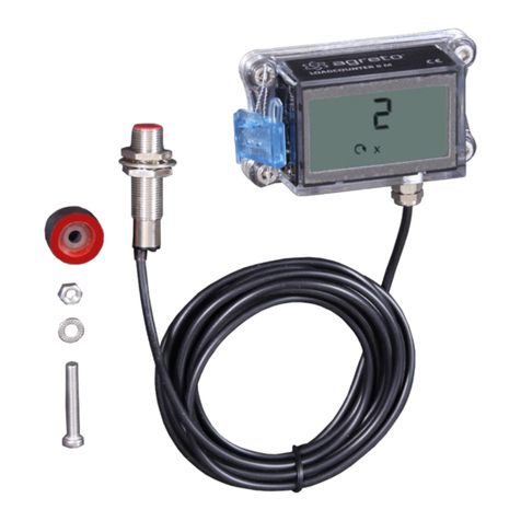
Agreto AgriCounter Drive User manual

© AGRETO electronics GmbH
User Manual
Acre meter AGRETO AgriCounter Drive

AGRETO AgriCounter Drive
© AGRETO electronics GmbH page:2
Content
1Introduction........................................................................................................... 3
2Scope of delivery .................................................................................................. 3
3Intended use......................................................................................................... 3
4Security................................................................................................................. 4
4.1 Safety instructions for the buyer......................................................................................4
4.2 Safety instructions for the operator .................................................................................4
4.3 Personal protective equipment .......................................................................................4
4.4 Residual risks..................................................................................................................5
5Technical specifications ....................................................................................... 5
6Configuration ........................................................................................................ 6
6.1 Selection of the operating mode.....................................................................................6
6.2 Operating Keys ...............................................................................................................8
6.3 Setting the operating mode ............................................................................................8
6.4 Setting the parameters....................................................................................................8
6.5 Zeroing the counter.......................................................................................................11
7Assembly ............................................................................................................ 11
7.1 Positioning of the meter ................................................................................................11
7.2 Fixing the mounting plate..............................................................................................12
7.3 Fastening the counter ...................................................................................................13
7.4 Attaching the seal .........................................................................................................13
8Working with the device...................................................................................... 14
8.1 Reading the area (mode 2A, 2B) ..................................................................................14
8.2 Reading the distance (mode 2C, 2D) ...........................................................................14
8.3 Reading the revolutions (mode 2E, 2F) ........................................................................14
8.4 Reading the speed (mode 2G) .....................................................................................14
8.5 Reading the hours (mode 2B, 2D, 2F) ..........................................................................15
8.6 Symbols on the display.................................................................................................15
9Maintenance and cleaning ................................................................................. 17
10 Troubleshooting.................................................................................................. 17
10.1 The battery symbol lights up .....................................................................................17
10.2 Area is not counted correctly.....................................................................................17
10.3 Distance or speed is not counted correctly ...............................................................17
10.4 Revolutions are not counted correctly .......................................................................17
10.5 Operating hours are not counted completely............................................................18
10.6 Too many operating hours are counted ....................................................................18
10.7 Damage to the device ...............................................................................................18
11 Warranty ............................................................................................................. 19
12 Disposal.............................................................................................................. 19
13 Imprint................................................................................................................. 20

AGRETO AgriCounter Drive
© AGRETO electronics GmbH page:3
1Introduction
Thank you for choosing an AGRETO AgriCounter Drive. You have acquired a
robust tool for daily use.
Please read this manual carefully before using the equipment.
2Scope of delivery
1 Display unit
1 Mounting plate
2 AAA batteries
5 Seals
Mounting parts
Manual
3Intended use
The AGRETO AgriCounter Drive is designed to measure the number of
revolutions of wheels and other rotating parts on all types of machines and
devices.
Activation takes place by direct rotation of the counter itself.
By multiplying the revolutions with the wheel circumference, a traveled distance
can be calculated. An area can be calculated by multiplying it by the working
width of the implement.
The counter has different operating modes. Depending on the setting, the
operating hours can also be counted. The operating hours are determined by
movement or vibration of the machine, regardless of the rotation.

AGRETO AgriCounter Drive
© AGRETO electronics GmbH page:4
4Security
4.1 Safety instructions for the buyer
Important!
Make sure that every person who works for the first time with the
AGRETO AgriCounter, has read and understood this manual.
4.2 Safety instructions for the operator
DANGER!
The AGRETO AgriCounter may only be operated by persons who
are familiar with the operation of the device.
CAUTION!
Keep the work area clean! Soiled areas contributes to accidents.
RISK!
Risk of injury from tip-over / fall and inattention while working with
the measuring instrument during getting on and off the tractor.
4.3 Personal protective equipment
WARNING!
For individuals who work with the device or reside in the working
area the wearing of safety shoes are required.

AGRETO AgriCounter Drive
© AGRETO electronics GmbH page:5
4.4 Residual risks
When using the device residual hazards for persons and objects may occur that
can‘t be prevented by design or technical protection measures.
WARNING!
The AGRETO AgriCounter must not be operated in explosive
areas.
5Technical specifications
Packaging dimensions: 220x160x50 mm (LxWxH)
Package weight: 450 g
Device dimensions: 73 x 52 x 33 mm (WxHxD)
Weight: 230 g
Dust and waterproof plastic housing
3 internal control buttons for configuration
Six-digit display with 11 mm digit height
Icons for displaying additional information
Powered by 2 x AAA batteries
Battery life approx. 3 years

AGRETO AgriCounter Drive
© AGRETO electronics GmbH page:6
6Configuration
6.1 Selection of the operating mode
The AGRETO AgriCounter Drive has 7 operating modes, in which various data
can be recorded.
First, decide which operating mode is suitable to your application, set the
required settings if necessary, and then mount the counter on your machine!
Operating mode 2A –Area (standard)
In this operating mode, the counter registers the number of revolutions around
its own axis. The area is calculated from the number of revolutions per 100 m
and the working width, the sum oft he area is displayed.
The counter is mounted on the rim of a wheel or on a part that rotates
depending on the path.
Operating mode 2B –Area and hours
In this mode, the area is counted as in 2A.
Additionally the operating hours are recorded. The counter reacts to vibrations
and movements of the machine independently of the rotation and shows the
total number of operating hours too.
Operating mode 2C –Distance
In this mode, the counter registers the number of revolutions around its own
axis. The distance is calculated from the number of revolutions per 100 m and
the total is displayed.
The counter is mounted on the rim of a wheel or on a part that rotates
depending on the path.
Operating mode 2D –Distance and hours
In this mode, the distance is counted as in 2C.
Additionally the operating hours are recorded. The counter reacts to vibrations
and movements of the machine independently of the rotation and shows the
total number of operating hours too.

AGRETO AgriCounter Drive
© AGRETO electronics GmbH page:7
Operating mode 2E –Revolutions
In this mode, the counter registers the number of revolutions around its own
axis, the total is displayed.
The counter can be mounted on any rotating part.
Operating mode 2F –Revolutions and hours
In this mode, the revolutions are counted as in 2E.
Additionally the operating hours are recorded. The counter reacts to vibrations
and movements of the machine independently of the rotation and shows the
total number of operating hours too.
Operating mode 2F –Speed
In this mode, the current speed is displayed by recording the revolutions of the
counter around its own axis and the set number of revolutions per 100 m.
The counter is mounted on the rim of a wheel or on a part that rotates
depending on the path.
Overview:
Operating mode
Output
Activation by
2 A (default)
Area
Rotation
2 B
Area
Operatin hours
Rotation
Vibration / movement
2 C
Distance
Rotation
2 D
Distance
Operatin hours
Rotation
Vibration / movement
2 E
Revolutions
Rotation
2 F
Revolutions
Operatin hours
Rotation
Vibration / movement
2 G
Speed
Rotation

AGRETO AgriCounter Drive
© AGRETO electronics GmbH page:8
6.2 Operating Keys
The control buttons are located inside the device and accessible from the back
with the mounting plate removed.
To change settings, look at the buttons and
then turn the device with the display to the
front to read the display.
Button
Definition
Function
M
Menu
Entry into the menu
Continue to the next parameter, exit from the menu
-
Minus
Back to the previous step
Decrease a parameter by 1
+
Plus
Continue to the next step
Increase a parameter by 1
6.3 Setting the operating mode
On delivery, the operating mode 2A is preset.
To change the operating mode, press and hold the "M" button for 3 seconds.
After releasing the key, the display briefly shows "MOdE" and then the current
setting of the operating mode appears.
Change to the desired operating mode with the "+" or "-" buttons.
The "M" key (or if you wait 10 seconds) will save the selection and exit the menu.
Please note: Changing the operating mode will reset all totals to 0.
6.4 Setting the parameters
In order to customize the working method of the counter for the individual
purpose, various parameters can be set. Not all parameters are available in
each mode.
To determine the area, distance or speed, the parameter r100 - revolutions per
100 m must be set in any case.

AGRETO AgriCounter Drive
© AGRETO electronics GmbH page:9
To determine the area, the parameter WidE - working width must be set.
The parameters SENS and hoLd are only relevant for the hour counting; the
default settings should be suitable for most applications.
To open the parameter menu, briefly press the "M" key. The first parameter that
is relevant for the set operating mode appears on the display.
The name of the parameter is displayed for two seconds, then the set value
appears.
Use the "+" or "-" keys to change the value of the parameter. For parameters
with a large setting range, the value can be changed more quickly by holding
the "+" or "-" button for 3 seconds.
Use the "M" key to change to the next parameter, the set value is saved. After
the last parameter, the first parameter is displayed again.
To exit the menu, press and hold the "M" button for three seconds, or simply
wait 10 seconds without pressing a button.
Parameter r100 –Revolutions per 100 m (modes 2A, 2B, 2C, 2D, 2G)
This parameter specifies the number of revolutions of the counter around its
own axis per 100 meters traveled.
You can calculate the number from the circumference of the wheel on which the
meter is mounted by dividing 100 by the circumference in meters.
It is better to mark out a distance of 100 meters, drive along it and count the
number of revolutions.
The number can be set with an accuracy of 0.05.
Adjustable range: 10 to 300, default value: 60
Parameter WidE –Working width (modes 2A, 2B)
This parameter defines the working width of the device in meters. This width is
used to calculate the area. Therefore, take into account possible overlaps.
The number can be set with an accuracy of 0.05.
Adjustable range: 0.05 to 50, default value: 3
Parameter SENS - Sensitivity (modes 2B, 2D, 2F)
This parameter determines from which intensity of a movement the count is
triggered, ie how strong the vibration or movement must be. The higher the
value, the stronger the movement must be to trigger or continue the count.
0 = highest sensitivity (counts even on very small movements)
2 = a running internal combustion engine is already detected

AGRETO AgriCounter Drive
© AGRETO electronics GmbH page:10
4 = default
10 = lowest sensitivity (only counts for extreme movements)
The parameter SENS is related to the parameter hoLd, since a movement must
always have a certain intensity and must be present for a certain period of time
in order to trigger the summation.
Parameter hoLd –Holding time (mode 2B, 2D, 2F)
In idle mode, this parameter determines the time in seconds that the counter
waits after a first move to actually start the totalization permanently. If there is
another movement within the set time (which is strong enough), the time from
the first movement is added up and the counter is in counting mode. If there is
no further movement within the set time, the counting is stopped and the sum is
reset to the initial value.
1 = summation starts immediately after the first movement
20 = default
100 = summation is started after 100 seconds
In counting mode, this parameter determines the length of a rest period in
seconds, during which the count continues without interruption. If another
movement follows within the set time (which is strong enough), the complete
time is added up, including the rest phase. If the rest period lasts longer than
the set time, the count stops and the sum is reset to the value at the beginning
of the rest phase. The meter is now in idle mode.
1 = summation is stopped immediately at the end of the movement
20 = default
100 = A rest period of up to 100 seconds is counted
As long as the meter is not sealed, you can remove it at any time and change
the angle settings. For optimization, place your machine on a horizontal
surface.
Parameter UnIt - Display format (modes 2B, 2D, 2F)
This parameter determines the format of the hour display.
00:59 = default setting, display in hours and minutes (hhhh:mm)
00,99 = display in hours with 2 decimal places (hhhh,hh)
By default, the display is in hours and minutes, and the colon is used as the
separator.

AGRETO AgriCounter Drive
© AGRETO electronics GmbH page:11
If necessary, you can change the display to decimal hours, here the comma is
used as separator.
Parameter LOSP –Low speed (modes 2E, 2F)
This parameter can be used to switch to a special counting method at low
speeds for calculating the number of revolutions.
0 = normal calculation mode (default)
1 = low speed calculation mode
Set the parameter to 1 if the counter rotates slower than approximately one
revolution per minute.
6.5 Zeroing the counter
To reset the counter, press and hold all 3 buttons together for 3 seconds. When
released, all totals are set to 0.
7Assembly
Only start with the assembly once you have clarified whether a change in the
configuration is necessary for your application. Please read the chapter
"Configuration" before.
7.1 Positioning of the meter
Fort he accurate counting process the AgriCounter Drive must rotate depending
to the path. It must be mounted directly on the rim of a wheel or on another
path-dependent rotating part. The number of revolutions should be between 5
and 200 per minute during operation.
The meter must be aligned so that:
- the underside of the meter (the side opposite the label) points approximately
towards the center of the axis of rotation
- the front of the meter is approximately parallel to the plane of rotation
- the meter is mounted as close as possible to the center in order to reduce
centrifugal forces

AGRETO AgriCounter Drive
© AGRETO electronics GmbH page:12
Mounting examples:
7.2 Fixing the mounting plate
On delivery, the meter is mounted on the
mounting plate. Disassemble the meter from
the mounting plate.
Hold the mounting plate in the desired
position to the desired mounting position.
Use the mounting plate as a template and
mark the 2 holes with a pin.
Hit one notch each with a grain.
Drill the 2 holes with a 4.2 mm diameter drill.
Deburr the 2 holes.
Use a M5 screw tap to cut a thread in each
hole.
Use the 2 M5x25 allen screws and the 2 aluminum washers and screw the
base plate to the machine. Note that the sealing surface of the base plate
is pointing towards the meter.

AGRETO AgriCounter Drive
© AGRETO electronics GmbH page:13
7.3 Fastening the counter
Place the counter on the base plate.
Use the 4 allen screws M5x8. Two of them
have a small hole for the seal wire, use these
two on the side where you want to attach the
seal.
First, pull slightly down all 4 screws, and then
tighten every screw again so that the housing
is evenly pressed against the mounting plate.
7.4 Attaching the seal
Thread the seal wire through the holes in the
two screws.
Thread both ends of the wire through a hole
in the seal.
Slide the seal as close as possible tot he
meter and at the same time tighten the wire.
Close the seal.
If the hole of one oft he screws is not accessible,
you can also drill a small hole in the housing bar
between the two screws and pull through the seal
wire here.

AGRETO AgriCounter Drive
© AGRETO electronics GmbH page:14
8Working with the device
The AgriCounter Drive permanently shows the results of the summation or
calculation depending on the mode, operation for reading is not provided. The
display is updated approximately every 5 seconds.
8.1 Reading the area (mode 2A, 2B)
The sum of the counted area in hectares is
displayed with 2 decimal places, and the ha
symbol lights up.
8.2 Reading the distance (mode 2C, 2D)
The total of the counted distance in
kilometers is displayed with 2 decimal
places, and the km symbol lights up.
8.3 Reading the revolutions (mode 2E, 2F)
The sum of the counted revolutions is
displayed, the symbol with the rotary arrow
and the x light up.
8.4 Reading the speed (mode 2G)
The current speed is displayed with 2
decimal places, and the km and h symbols
light up.

AGRETO AgriCounter Drive
© AGRETO electronics GmbH page:15
8.5 Reading the hours (mode 2B, 2D, 2F)
In these operating modes, the sum of the area (or distance or revolutions) and
the sum of the hours counted are displayed alternately every approx. 5
seconds. The symbol h indicates that the number displayed is the sum of the
hours.
If the colon is visible as a separator, it is
hours and minutes.
If the comma is visible as a delimiter, it is
decimal with 2 decimal places.
8.6 Symbols on the display
Below the hour display there are various
icons for displaying additional information.
The wavy line means that the counter is currently detecting movement
or vibration and is in counting mode.
The rotation arrow together with the x means that the number
displayed is the sum of the revolutions
Both light up in the setting mode when entering the number of revolutions per
100 meters.
The km display means that the number displayed is the sum of the
kilometers.
The h means that the displayed values are hours.

AGRETO AgriCounter Drive
© AGRETO electronics GmbH page:16
The display ha means that the number displayed is the sum of the
hectares.
The s lights up in the setting mode when a parameter value is expected in
seconds.
The m lights up in setting mode when a parameter value in meters is
expected.
The crossed-out battery icon lights when the batteries are low and
you need to replace them.

AGRETO AgriCounter Drive
© AGRETO electronics GmbH page:17
9Maintenance and cleaning
The AgriCounter basically does not require ongoing maintenance.
If the display is dirty, clean it for reading.
If the battery symbol is lit, replace the batteries.
10Troubleshooting
10.1 The battery symbol lights up
The batteries need to be replaced, follow these steps:
Remove the seal and the seal wire.
Remove the housing and remove the meter.
Remove the old batteries and dispose them properly.
Insert 2 new AAA batteries into the device in the specified direction.
Mount the counter again on the mounting plate.
Seal the device again with a new seal wire and a new seal.
10.2 Area is not counted correctly
Observe the specifications according to chapter „Positioning oft he meter“
Check the parameter r100 –Revolutions per 100 m
Check the parameter WidE –Working width
10.3 Distance or speed is not counted correctly
Observe the specifications according to chapter „Positioning oft he meter“
Check the parameter r100 –Revolutions per 100 m
10.4 Revolutions are not counted correctly
Observe the specifications according to chapter „Positioning oft he meter“

AGRETO AgriCounter Drive
© AGRETO electronics GmbH page:18
10.5 Operating hours are not counted completely
The movements or vibrations on the machine are probably relatively low, so that
the necessary intensity for the count is not reached.
Set the parameter SENS down so that the counter triggers even with minor
movements.
To hold longer periods of rest during operation, set the parameter hOLd
upwards.
10.6 Too many operating hours are counted
Perhaps the machine is exposed to light movements at standstill, which are
recorded as operating hours.
Set the parameter SENS upwards so that the counter only triggers for
larger movements
To prevent idle phases from being counted during operation, set the hOLd
parameter down.
10.7 Damage to the device
Contact the manufacturer or your dealer

AGRETO AgriCounter Drive
© AGRETO electronics GmbH page:19
11Warranty
Over and above statutory warranty for AGRETO AgriCounter Drive following
warranty provisions apply :
The AGRETO electronics GmbH guarantees the function and repairs or
replaces all the parts that have a material or manufacturing damage within
the warranty period.
Warranty services will be performed by the AGRETO electronics GmbH.
The decision on the existence of a warranty claim is sole responsibility of
the AGRETO electronics GmbH.
The warranty period begins with the first accounting to an end customer
and ends 5 years from this date of invoice.
Prerequisite for warranty service are the presentation of the original invoice
and compliance with all elements of this instruction manual.
Excluded from warranty are wear, normal wear and tear, damage due to
misuse, negligence or accident.
When processing a warranty claim transport costs incurred will be charged
to the buyer.
12Disposal
Dispose of the device as part of the final shutdown or parts of it
environmentally friendly and sorted (metal to the respective metal
scrap, plastic to the plastic waste, etc. - do not dispose as
household waste)!
Detailed information can be found in directive 2002/96 / EC

AGRETO AgriCounter Drive
© AGRETO electronics GmbH page:20
13Imprint
All information, specifications and illustrations are as of 2020, subject to
technical changes or design changes.
All information in this manual are supplied without liability despite careful
preparation. A liability by the author is excluded.
Copyright © 2020, AGRETO electronics GmbH
AGRETO electronics GmbH
Pommersdorf 11
A-3820 Raabs
Tel.: +43 2846 620
Fax: +43 2846 620 19
Internet: www.agreto.com
Table of contents
Other Agreto Measuring Instrument manuals