Agri Alert 9600 User manual

AGRI-ALERT 9600
ALARM SYSTEM
USER MANUAL
M 890-00279 rev. 14 K 895-00004 rev. 00

WARNINGS
The warranty can be void if this product is used in a manner not specified by the manufacturer.
Every effort has been made to ensure that this manual is complete, accurate and up-to-date. The information
contained in it is however subject to change without notice due to further developments.
Manufacturer:
Viatron Electronics
5200, Armand-Frappier
St-Hubert (Quebec)
Canada
J3Z 1G5

TABLE OF CONTENTS
SYSTEM OVERVIEW ................................................................................ 7
CHAPTER ONE: USER INTERFACE ............................................................ 9
1.1 FRONT PANEL ........................................................................................... 9
1.2 MEANING OF STATUS LEDS ..................................................................... 10
1.3 DISPLAYING A PARAMETER ...................................................................... 10
1.4 MODIFYING A PARAMETER ....................................................................... 11
1.5 HOW TO USE THE MENUS ........................................................................ 12
1.6 SYSTEM MESSAGES................................................................................. 14
1.7 BURGLAR ZONES..................................................................................... 15
1.8 ACKNOWLEDGING AN ALARM.................................................................. 16
1.9 TELEPHONE INTERFACE............................................................................ 17
CHAPTER TWO: SYSTEM INITIALIZATION .............................................. 21
2.1 POWER UP .............................................................................................. 21
2.2 SYSTEM CLOCK....................................................................................... 21
2.3 USER ID MESSAGE ................................................................................... 23
2.4 ZONE ID MESSAGE .................................................................................. 25
2.5 DELETING ALL ID MESSAGES.................................................................... 27
2.6 PASSWORD PROTECTION ......................................................................... 28
2.6.1 Modifying the Master Password ....................................................................................... 28
2.6.2 Enabling / Disabling the Password Feature .......................................................................... 30
2.6.3 Modifying the User Passwords ......................................................................................... 31
2.6.4 Erasing All User Passwords ............................................................................................. 32
2.7 TEMPERATURE UNITS .............................................................................. 33
2.8 POWER FAILURE ALARM .......................................................................... 34
2.9 TEST PROCEDURE.................................................................................... 35

4AA-9600.rev.14
CHAPTER THREE: COMMUNICATION PARAMETERS................................. 36
3.1 INTRODUCTION ....................................................................................... 36
3.2 DIALING INFORMATION............................................................................ 38
3.2.1 Busy Line Tries.............................................................................................................. 38
3.2.2 Message Repetitions ......................................................................................................38
3.2.3 Call Start Delay............................................................................................................. 38
3.2.4 Time Between Calls .......................................................................................................38
3.2.5 Restore Calls ................................................................................................................ 39
3.2.6 # of Call Repetitions....................................................................................................... 39
3.2.7 Alarm Recall Time ......................................................................................................... 39
3.2.8 Pause Delay Key ........................................................................................................... 39
3.3 PHONE SETTINGS .................................................................................... 40
3.3.1 Phone Numbers ..............................................................................................................40
3.3.1.1 Home .................................................................................................................... 41
3.3.1.2 Cellular.................................................................................................................. 41
3.3.1.3 Beeper .................................................................................................................. 42
3.3.1.4 Pager ....................................................................................................................42
3.3.1.5 Alarm Report .......................................................................................................... 45
3.3.1.6 Test Report ............................................................................................................45
3.3.2 Phone Groups ................................................................................................................ 47
3.3.2.1 Edit Group Label....................................................................................................... 48
3.3.2.2 Setting Day Phone Numbers ......................................................................................48
3.3.2.3 Setting Night Phone Numbers ....................................................................................49
3.3.2.4 Setting Weekend Phone Numbers ............................................................................... 51
3.3.2.5 Assigning Zones to Phone Groups ............................................................................... 52
3.3.2.6 Assigning System Alarms to a Phone Group ................................................................. 53
3.3.2.7 Deleting a Phone Group ............................................................................................ 53
3.3.3 Phone Starting Time ....................................................................................................... 54
3.4 ON SITE LISTENING.................................................................................. 55
3.5 RINGS / ANSWERING MACHINE................................................................. 57
CHAPTER FOUR: SPECIAL FUNCTIONS ................................................... 59
4.1 TROUBLE INFORMATION ........................................................................... 59
4.2 STANDBY MODE ..................................................................................... 60
4.2 STANDBY MODE ..................................................................................... 60
4.3 PROGRAMMABLE OUTPUTS...................................................................... 61
4.3.1 Switched Outputs on the Agri-Alert 9600 ..........................................................................61
4.3.2 0-10V Output on the Agri-Alert 9600 ............................................................................... 63
4.3.3 Switched Outputs on Other Devices.................................................................................. 63

5
AA-9600.rev.14
CHAPTER FIVE : ALARM MANAGEMENT.................................................. 66
5.1 ALARM VALIDATION: SUMMARY OF EVENTS............................................ 66
5.2 SYSTEM ALARMS .................................................................................... 67
5.3 OUTDOOR TEMPERATURE COMPENSATION ON TEMPERATURE ALARMS ...... 68
5.3.1 To Activate / Deactivate the Outdoor Temperature Compensation:.......................................... 70
5.3.2 To Set the Offset Temperature: ....................................................................................... 71
5.4 ALARM MEMORY ..................................................................................... 72
5.5 ZONE STATUS DISPLAY ........................................................................... 73
5.5.1 Adjusting Set Points....................................................................................................... 75
5.5.2 Adjusting Curve Offset Values ......................................................................................... 77
5.5.3 Adjusting Curve Points .................................................................................................... 78
5.5.4 Enabling / Disabling Temperature Curve ............................................................................. 79
5.5.5 Adjusting the Recognition Time ........................................................................................ 80
5.5.6 Copying Zone Set Points to Another Zone .......................................................................... 80
5.5.7 Resetting Minimum / Maximum Values ............................................................................... 81
5.6 PARTITIONS ............................................................................................ 82
5.6.1 Adding a zone ............................................................................................................... 83
5.6.2 Deleting a zone ............................................................................................................. 83
5.6.3 Deleting a partition ........................................................................................................ 84
5.7 BYPASS / ACTIVATE FUNCTION ................................................................ 85
5.7.1 Changing Zone Status .................................................................................................... 85
5.7.2 Changing Partition Status................................................................................................ 86
5.7.3 Viewing Bypassed Zones.................................................................................................. 86
5.8 ENTRY DELAY ......................................................................................... 87
5.9 EXIT DELAY ............................................................................................ 88
5.10 SIREN PARAMETERS............................................................................... 89
5.10.1 Siren Delay.................................................................................................................. 89
5.10.2 Siren Time On ............................................................................................................. 90
TROUBLESHOOTING GUIDE .................................................................... 91
APPENDIX A: MAXIMUM WIRE LENGTHS................................................ 93
APPENDIX B: BACKUP BATTERY LIFE SPAN............................................ 94
APPENDIX C: EVENT CODES.................................................................. 95
GLOSSARY OF TERMS ..........................................................................102
WIRING DIAGRAMS ..............................................................................104
TECHNICAL SPECIFICATIONS ................................................................106
REGISTRATION CARD ...........................................................................107

6AA-9600.rev.14
NOTICE
Every effort has been made to ensure that this manual is complete, accurate and up-to-date. The information
contained in it is subject to change without notice due to further developments.
LIST OF TABLES AND FIGURES
Figure 1: Calling a Pager Number ............................................................................. 44
Figure 2: Outdoor Temperature Compensation ............................................................ 68
Figure 3: Critical Temperature Monitoring .................................................................. 69
Figure 4: Monitoring the Indoor-Outdoor Temperature Difference ................................... 69
Figure 5: Temperature Input Without Temperature Curve ............................................. 76
Figure 6: Temperature Input with Temperature Curve .................................................. 77
Figure 7: Example of Partitioning .............................................................................. 82
Table 1: Pager Codes Used by the Agri-Alert System .................................................. 43
Table 2: System Alarms ........................................................................................ 67

7
AA-9600.rev.14
SYSTEM OVERVIEW
The Agri-Alert system is a complete alarm detection and management system for
agricultural applications. It can handle up to 96 alarm inputs spread over several
buildings. The following diagram shows how the different components are connected
together.
Figure 1: AA9600 Installation Layout
BRIDGE-A
TO TEMPERATURE
CONTROLLER
NETWORK
S

8AA-9600.rev.14
DEVICE DESCRIPTIONS
The complete system can include up to 99 devices.
AA9600: the main system with 8 basic zones, two relays and one microphone. Two
extension cards can be added allowing 16 additional zones.
TP-800: a remote extension device that adds 8 zones and a programmable output to
the main system.
KP-400: a keypad for displaying system data from a remote location. Includes 4 dry
contact, burglar or temperature zones and one programmable output.
KPB-400: a dust- and moisture-tight keypad for displaying system data from a remote
location. Includes 4 dry contact, burglar or temperature zones and one programmable
output.
LB-9600: a device containing 96 LEDs for indicating zone status.
BRIDGE: a computer communication device. Allows the user to operate the complete
system from a computer keyboard or modem. Datalogs up to 4 Agri-Alert systems (4
X 96 zones). When used with a Combridge-1 card, the Bridge is compatible with
AgBus, allowing the Agri-Alert to fetch temperature readings from existing controller
networks (see installer manual, sec. 3.4.3).
!
WARNING
Caution. Carefully read the following text for it contains important infor-
mation which, if ignored, may cause the controller to operate improperly.
Pay attention. The following text contains very useful information.
KEYS TO SYMBOLS IN THE MANUAL

9
AA-9600.rev.14
CHAPTER ONE: USER INTERFACE
The system displays and prompts for information by using the alphanumeric screen.
The keypad is used for data entry and for enabling and disabling the various system
functions. The speaker on the front panel delivers voice messages. A built-in piezo-
electric warns of illegal entries (3 short beeps) and beeps once when a valid key is
pressed. The integrated microphone on the front panel is used to record the user ID
message and provide on-site listening. The status of some subsystems is displayed
using LEDs on the front panel.
1.1 FRONT PANEL
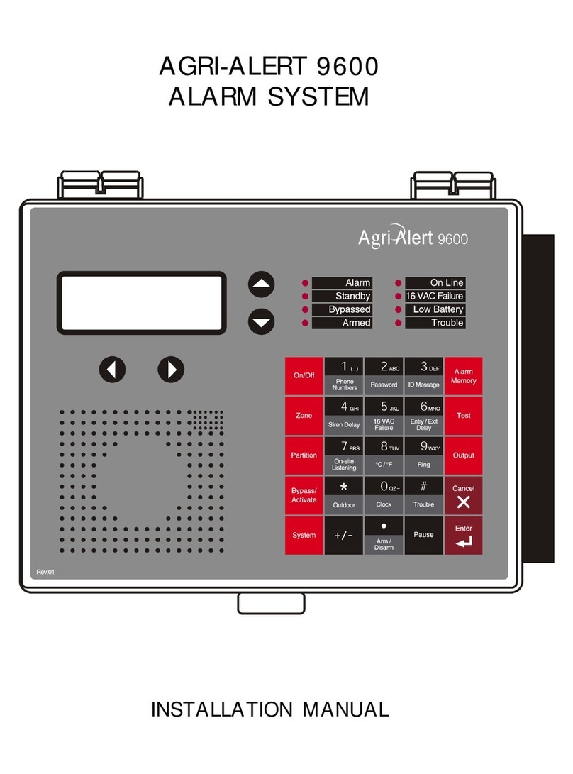
1 - Display Screen — An alphanumeric display used to provide information and
prompt for inputs.
2 - Cursor Keys — Used to step through menu items during data entry and for delet-
ing the last character entered.
3 - Speaker — System identification and alarm messages.
4 - Integrated Microphone — Records the ID message and provides on-site listening
input.
5 - Keypad — User inputs and information requests.
6 - System LEDs — Status of various subsystems (see table on following page).
1
2
4
3 5
6

10 AA-9600.rev.14
1.2 MEANING OF STATUS LEDS
1.3 DISPLAYING A PARAMETER
When you select a parameter to input or modify, the system begins by displaying the
current value or status of the parameter. If the message to display is longer than the
size of the window, it will be scrolled to the left. The display pauses at the end of
each screen to allow time to read the message. You can exit prematurely from a
display sequence at any time by pressing the Cancel key. This will place you in
program mode and allow you to modify the parameter values (see next section). To
exit from this function as well, press the Cancel key once again.
DELGNINAEM
MRALA
erasnoitidnocmralaeromroenonehwdetavitcasiDELsihT
sadegdelwonkcasimralaehtnehwffodenrutsiDELehT.detceted
sahemittesereht,stsixeregnolonnoitidnocmralaehtsagnol
.evitcaerasmralarehtoondnadespale
YBDNATS
.edomybdnatsnisimetsystrelA-irgAehtnehwdetavitcasiDELsihT
mralarofstupnirosnesehtgnirotinomspotsmetsyseht,edomsihtn
signirotinomlamronnehwffodenrutsiDELehT.snoitidnoc
.demuser
SSAPYB ehT.dessapyberasenozeromroenonehwdetavitcasiDELsihT
.dessapybyltnerrucerasenozonnehwffodenrutsiDEL
DEMRA .demraerasenozralgrubehtnehwdetavitcasiDELsihT
ENILNO .enilenohpeletehtsesumetsysehtnehwdetavitcasiDELsihT
CAV61
ERULIAF
CAV61ehtnodetcetedsieruliafrewopanehwdetavitcasiDELehT
.tiucricylppus
WOL
YRETTAB .wolsiegatlovyrettabpu-kcabehtnehwdetavitcasiDELsihT
ELBUORT
:nehwdetavitcasiDELsihT
ehtmorfdeviecerlangisehthtiwstcilfnocnoitarugifnocenoza-
rosnes
yrdroerutarepmetanodetcetedsitiucricneporotrohseriwa-
.tupniRLOEhtiwtcatnoc
.RLOEDhtiwtupnitcatnocyrdanodetcetedsitiucricnepona-
.RLOEDhtiwtupnitcatnocyrdanodetcetedsitrohseriwa-
.tupniAm02-4anodetcetedsitrohsronepoeriwa-
.detcetedsimelborperawtfosa-
detcetedsierawtfoss'eludomehtnomelborpa-
rewopBSwoleludoma-
.eludomanoderuccomelborpnoitacinummoca-

11
AA-9600.rev.14
If a parameter is not completely defined when you try to display it, the message
INCOMPLETE DATA appears on the screen. This may be an indication that the sys-
tem will not behave as expected. If, for example, a zone input is not completely
configured, the system will not monitor the zone for alarm conditions. Before enabling
the system for normal operation, make sure all parameters are properly defined. In
the case of phone numbers and zones, the system will display a message every 3
seconds telling the user which zones and phone numbers are incomplete.
1.4 MODIFYING A PARAMETER
If you have selected a parameter and the display sequence is now finished, you can
begin modifying the parameter values. The following screen appears on the display:
This screen is also displayed if the display sequence described above was cancelled
prematurely. If you want to modify the parameter values at this point, press the Enter
key to modify the parameter. The system will prompt for the information re-
quired to define the parameter. When the parameter is defined by a numerical value,
a range of possible values is displayed. For example, if you select the Exit Delay
parameter followed by MODIFY, the system responds:
The number of spaces provided for input corresponds to the maximum number of
digits allowed. In this example, one space is provided for the minutes and 2 spaces
are provided for the seconds. The cursor positions itself on the first space and blinks
until a digit is entered. If no response is given within 30 seconds, the system will
cancel the input session and return to the Date/Time display. If more than one value
is required in the same screen (in this example: hours and minutes), press Enter after
TO MODIFY. . . . . (↵↵
↵↵
↵)
TO QUIT. . . . . . . (X)
ENTER NEW DELAY
_ MIN: _ _ SEC

12 AA-9600.rev.14
entering the first value to step to the following one. To enter a zero value, you cannot
simply press Enter; you must type 0 and Enter.
If you make a typing mistake, you can backstep using the back arrow key under-
neath the display window before pressing Enter. The cursor will position itself accord-
ingly. You can enter a negative value if this is allowed (for example, a negative tem-
perature value) by pressing the key either before or after the digits.
After entering a value using the numerical keypad, press Enter to register the value. If
the value entered falls outside the permissible range for that parameter, the system
will beep three times and wait for you to modify the input using the back arrow key.
1.5 HOW TO USE THE MENUS
Menus are used to select a parameter or to assign a predetermined value to a parameter.
If the menu is comprised of only two items, they are displayed on the screen at once. For
example, when you press the Clock key
QZ-
Clock
, followed by Enter to modify, the following
menu appears:
You simply type the number of the item to select that item (no need to press the Enter
key). When more than two menu items are involved, the system will display one item
at a time and allow the user to scroll through the menu using the up and down-arrow
keys . Each menu item is followed by an arrow symbol to locate the current
position in the menu. Once a menu item is selected, other sub-menus may appear to
further define the input. For example, if you press the System key , the following
sub-menu appears:
DATE . . . . . . . . . (1)
TIME . . . . . . . . . (2)
SOFTWARE
REV XXXXXX

13
AA-9600.rev.14
The first menu item is PROGRAM ZONES. The arrow following the item means you are
at the top of the menu. If you press the down-arrow , the second item appears:
The arrows indicate that menu items are to be found above and below the current
item. When you reach the end of the menu, the last item will have an up-arrow . To
select a menu item, press Enter.
SYSTEM
PROGRAM DIALING
SYSTEM
PROGRAM ZONES

14 AA-9600.rev.14
1.6 SYSTEM MESSAGES
When the display is not being used by the user, the system periodically scrolls various
status messages. These messages provide information on the status of zones, de-
vices and system functions. You can fast-forward the scroll by pressing the right-
arrow key . To stop the scroll, press any key. The following list gives the display
priority for zone status messages.
1. If a zone or telephone number is incorrectly configured, it is identified along with
the message INCOMPLETE DATA.
2. If a trouble is detected on a zone, the zone is identified along with the message
TROUBLE. If this is a temperature or dry contact zone with an end of line resistor, the
nature of the trouble is also displayed, i.e. SHORT-CIRCUIT or OPEN CIRCUIT. This
message continues to be scrolled as long as the user has not erased the trouble using
the Trouble key even if the problem has been fixed.
3. If a zone has an alarm, it is identified along with the message ALARM. If this is an
activated temperature zone, the current temperature is displayed, along with the high
(H) and low (L) set points and the critical temperature (C) (when appropriate).
4. In the case of activated temperature zones, the system displays the zone label,
current temperature, high (H) and low (L) set points and critical temperature (C) (when
appropriate). After a 3 seconds delay, the minimum and maximum temperatures are
displayed.
ZONE #45
SMALL BREEDER
INCOMPLETE DATA
ZONE #45
SMALL BREEDER
TROUBLE
SHORT-CIRCUIT
ZONE #45
SMALL BREEDER
87.5°F ALARM
L50, H85, C95

15
AA-9600.rev.14
1.7 BURGLAR ZONES
These zones are armed or disarmed as a group using a password. In a delay burglar
zone, alarm conditions are not signalled until a delay has elapsed. The Exit Delay
allows the user to leave the building while arming the system. The Entry Delay allows
the user to enter the building and disarm the system without setting off an alarm. At-
home arming zones allow the user to move about inside the building while protecting
the perimeter, i.e. windows and entry points. If the system is armed and no one has
left the building within the exit delay, at-home arming zones are bypassed by the
system (see installer manual, sec. 4.1.2).
The key sequence for arming or disarming is as follows:
followed by the password sequence
(default password set at
the factory).
If force arming is disabled (see below), all burglar zones must be in a normal state to
arm the system, i.e. no alarm conditions must be present. If the arming sequence
fails, zones with alarms are listed on the display (see installer manual, sec. 7.10).
When the system is armed, the system starts beeping and the screen immediately
displays a countdown of the exit delay (in minutes and seconds). The keypad is
locked at this point: the only key sequence allowed is the disarming sequence. After
the exit delay has elapsed, the system is armed and alarms are immediately declared
as they are detected for all activated burglar zones. The system displays the mes-
sage “BURGLAR ZONES ARMED” periodically on the screen.
When an alarm occurs in a burglar zone with an entry delay, the screen displays a
countdown of the entry delay. During this time, the piezoelectric loudspeaker beeps
(the loudspeaker stops when the key sequence is entered). If no one has disarmed
the system after the entry delay has elapsed, an alarm is declared. Disarming will
affect all currently active burglar zones. The system displays the message “BUR-
GLAR ZONES DISARMED” on the screen.
ZONE #45
SMALL BREEDER
82.0° F
MIN 65 MAX 78
ZONE #45
SMALL BREEDER
82.0° F
L50, H85, C95

16 AA-9600.rev.14
ENTER PASSWORD
_ _ _ _
ENTER PASSWORD
_ _ _ _
1.8 ACKNOWLEDGING AN ALARM
In order to notify the Agri-Alert system that an alarm message has been received, the
alarm must be acknowledged. There are several ways of doing this. If you are on-
site when an alarm is detected, enter your password (if the password feature is en-
abled) or simply press any key on the front panel to acknowledge. You can also ac-
knowledge an alarm over the phone when the Agri-Alert system reports the alarm
(see below) or by calling the Agri-Alert system yourself between phone dialouts (if the
time between calls is greater than zero).
Acknowledging from the keyboard:
When an alarm is detected, the following message is displayed:
1. Press 1to acknowledge. If the alarm is not acknowledged from the keyboard
within 15 seconds and the dialout sequence is enabled for the zone in alarm, the
dialout sequence will be launched. If the password feature is enabled, the system
prompts for a password before acknowledging.
2. When a user acknowledges an alarm, the siren stops ringing. If the dialout se-
quence is completed and no acknowledgment has been received, the alarms are
automatically acknowledged but the siren continues to ring; it must be acknowledged
separately from the keypad. In this case, the following message is displayed:
3. Press 1to acknowledge. If the password feature is enabled, the system prompts
for a password before acknowledging.
ACK ALARMS
ZONE # 3,10,45
ACK SIREN
PRESS . . . . . .<1>
ACK ALARMS
PRESS . . . . . .<1>

17
AA-9600.rev.14
1.9 TELEPHONE INTERFACE
The Agri-Alert system reports alarms over the phone. It can also be accessed over
the phone to obtain status reports. When calling the Agri-Alert, make sure the Ring
Until Answer and Answering Machine parameters are set properly (see Section 3.5).
Alarms: When an alarm occurs, the Agri-Alert system reports the alarm over the
phone to all the numbers programmed in its dialout sequence (see Chapter 3). The
following section outlines the dialogue session when a number is reached. A touch-
tone phone must be used to respond to the system prompts. When an alarm is ac-
knowledged, the Agri-Alert system stops dialing out.
“Hello, this is Agri-Alert”
[User ID Message is played over the phone]
Press the pound (#) key of the phone keypad to skip the alarm messages.
[Description of the alarm condition; for example: “Alarm Zone 1”]
“To select internal microphone - press 1”
“To select external microphone - press 2”
“On-site Listening”
[Microphone input is sent over the phone for on-site listening if enabled]
“Enter your password to acknowledge alarm message”
User enters four-digit password on the phone keypad. If an incorrect password is
entered, the system responds with “Wrong password”. The user has four tries in all
to enter the correct password. When the correct password is entered, the system
responds with “OK”.
“ For a complete status report — press 1
For a status report on a particular zone — press 2
To select output— press 3
For on-site listening — press 4
For a new selection — press 8
To hang-up — press 0”

18 AA-9600.rev.14
User enters selection on the phone keypad
Activating / Deactivating Relay Output
User enters ‘3’, for example, in response to above menu.
“ Enter module ID and press star.”
User enters module ID and press star.
“ Enter output number
User enters output number
“ Output X Activated / Deactivated
To activate - Press 4 / To deactivated - Press 6 ”
User enters ‘4’ for example in response to the above menu.
“ Your selection is to activate output X of module Y
If your selection is right - Press 5 “
User enters ‘5’
“ Output X of module Y activated “
Status Reports: You can dial into the Agri-Alert system and obtain status reports over
the phone (see Section 3.5). A touch-tone phone is needed to respond to the system
prompts. The following section outlines the dialogue session when the Agri-Alert
system answers the call. The system automatically hangs up when the status report
is finished.

19
AA-9600.rev.14
“Hello, this is Agri-Alert”
[User ID Message is played over the phone]
“Enter your password”
User enters four-digit password on the phone keypad. If an incorrect password is
entered, the system responds with “Wrong password”. The user has four tries in all
to enter the correct password. When the correct password is entered, the system
responds with “OK”.
“ For a complete status report — press 1
For a status report on a particular zone — press 2
To select output— press 3
For on-site listening — press 4
For a new selection — press 8
To hang-up — press 0”
[If a complete status report is selected, a status report is given for each zone with the
following information:
BYPASSED
DISABLED
INCOMPLETE DATA
ALARM — if zone is in alarm
ACTIVATED
TEMPERATURE READING — if zone is a temperature zone / in oC or oF depend-
ing on current settings; ]
[To step to the next zone before the status report for the current zone is finished,
press any key except “#”. To step to the system status report before the zone status
report is finished, press any key except “#”.]

20 AA-9600.rev.14
[The status of the system is given with the following possibilities:
LOW BATTERY / BATTERY OK
SYSTEM POWER OK / SYSTEM POWER DOWN
LOW / HIGH INTERNAL SYSTEM TEMPERATURE/ OK
12 VDC OUTPUT OK / 12 VDC OUTPUT DOWN
SIREN TROUBLE / SIREN OK
LOW / SBI OUTPUT / OK
RELAY 1 ACTIVATED / RELAY 1 DEACTIVATED
RELAY 2 ACTIVATED / RELAY 2 DEACTIVATED]
[To step to the next subsystem before the status report for the current subsystem is
finished, press any key except “#”. To exit the status report function, press “#”.
System returns to the main menu]
[If a status report on a particular zone is selected, the system prompts for the zone
number]
“Enter zone number and press ‘star’ (*) ”
[A status report is given for the selected zone with the following information:
BYPASSED
DISABLED
INCOMPLETE DATA
NOT INSTALLED
ALARM — if zone is in alarm
ACTIVATED
TEMPERATURE READING — if zone is a temperature zone / in oC or oF
depending on current settings; ]
[System returns to the main menu]
Other manuals for 9600
2
Table of contents
Other Agri Alert Security System manuals
