Agri Alert TP-800 User manual

Dieses Gerät muss gemäß den aktuellen
Installationsvorschriften sowie den geltenden
Bestimmungen installiert werden, die in allen Fällen
genauestens eingehalten werden müssen. Vor der
Durchführung von Installationen sollten Sie sich von
entsprechend zuständigen Behörden beraten lassen.
www.gsiag.com
Copyright © by GSI Electronics
Printed in Kanada
User Guide (EN)
Guide de l’utilisateur (FR)
Guía del usuario (ES)
用户指南 (ZH)
Guia do usuário (PT)
Pуководство пользователя (RU)
Anleitung (DE)
890-00596 rev. 00
TP-800
rev. 00


Chapitre 1 Connections and Configuration.................................................................................................7
Mounting the Enclosure ...............................................................................................................7
Grounding the System .................................................................................................................7
Schematic Diagram .....................................................................................................................8
Connecting the Modules Together Through the Serial Bus Interface.................................................9
Configuring a Zone......................................................................................................................9
Connecting the Sensors.............................................................................................................10
Connecting the Programmable Outputs.......................................................................................10
Setting the End of Line Jumpers .................................................................................................11
Assigning an Identification Number.............................................................................................11
895-00397 TP-800 5
NOTES
895-00397 TP-800 13

Chapter 1: Anschlüsse und Konfiguration
Nun blinkt die Nummer 2 auf der Anzeige auf.
3. Drücken Sie so lange wie erforderlich auf die Taste, um die ID-Nummer einzustellen.
4. Lassen Sie die Taste 5 Sekunden lang gedrückt, um die ID-Nummer zu speichern.
Die ID-Nummer hört nun auf zu blinken.
Table 1-1 Anzeigecodes
Lz ## Der lokale Bereich ## weist einen Alarm auf
Gz ## Der Systembereich ## weist einen Alarm auf
Er Fehler – wenden Sie sich an Ihren Händler. Störung
in einem TP800-Bereich
12 895-00397 TP-800
NOTES
6 895-00397 TP-800

1Connections and Configuration
Sujets abordés dans ce chapitre
▪ Mounting the Enclosure
▪ Grounding the System
▪ Schematic Diagram
▪ Connecting the Modules Together Through the Serial Bus Interface
▪ Configuring a Zone
▪ Connecting the Sensors
▪ Connecting the Programmable Outputs
▪ Setting the End of Line Jumpers
▪ Assigning an Identification Number
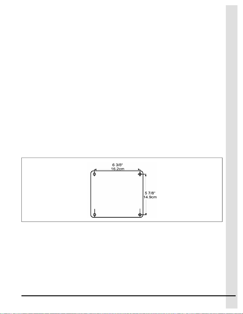
Mounting the Enclosure
1. Using the latch at the bottom of the enclosure, open the module.
2. Using the below template as a guide, mount the enclosure to the wall using 3/16 inch diameter
screws.
NOTE: Refer to the Agri Alert 128 manuals and quick start guide for more information on
configuration.
Grounding the System
A correctly grounded unit provides protection to the electronic components from damages caused by light-
ning surges and spikes, and from electrostatic discharges. Do not use the electrical ground for this
purpose.
What You Should Know
IMPORTANT: If you are using outdoor connections, mount the enclosure as close as possible to the entry
point of the outdoor wiring.
1. Drive the clean metal grounding rod at least 10 feet (3 meters) into the ground. If the bedrock is more
than 47 inches (1.2 meters) deep, drive the rod into the ground to bedrock level and bury any remain-
der horizontally at least 2 feet (600 millimeters) below ground level. If the bedrock is less than 47
895-00397 TP-800 7
Chapter 1: Anschlüsse und Konfiguration
Figure 1-1 Drei Beispiele von Lastanschlüssen
Einstellen der Abschlussjumper
Wenn mindestens zwei Module über die SBI zusammengeschlossen werden, müssen Sie die Abschluss-
jumper auf der Steckkarte entsprechend der Modulposition in der Reihe einstellen.
1. Machen Sie das letzte Modul der Kommunikationsleitung ausfindig und setzen Sie den Abschlusswi-
derstand auf Ja.
2. Setzen Sie die Abschlusswiderstände aller anderen Module auf Nein.
Zuweisen einer Identifikationsnummer
1. Schließen Sie nach dem Anschließen das Gehäuse und schalten Sie die Stromversorgung der Ein-
heit ein.
Auf der Anzeige erscheint nun ID 55. Hierbei handelt es sich um die standardmäßige Geräteidentifi-
kationsnummer (ID).
2. Drücken Sie zweimal auf die Taste Gear (Zahnrad), um die Geräte-ID-Nummerzu ändern.
895-00397 TP-800 11

Chapter 1: Anschlüsse und Konfiguration
Anschließen der Sensoren
Bevor Sie beginnen
Um Kurzschlüsse beim Anschließen der Geräte an die vorhandenen Klemmen zu vermeiden, dürfen Sie
die Drähte möglichst wenig bzw. um ca. 1/4 Zoll (7 mm) abisolieren.
Beispiele für Stromkreisverbindungen von Bereichen mit oder ohne einzelnem oder doppeltem Abschluss-
widerstand finden Sie in Anhang B.
1. Nachdem Sie die Drähte verbunden haben, führen Sie diese durch die elektrischen Ausbruchöffnun-
gen auf der Unterseite des Gehäuses.
Bekan-
ntma-
chung
Bohren Sie keine zusätzlichen Öffnungen in das Gehäuse. Durch
Nichtbeachtung der Vorschriften erlischt die Garantie ohne weitere Mitteilung.
2. Verwenden Sie einen Kabelhalter, um die Einheit wasserdicht zu machen.
3. Schließen Sie jeden Sensorstromkreis an eine Z-Klemme sowie an eine COM-Klemme an.
NOTIZ: Jede COM-Klemme wird von zwei Bereichen genutzt. Beispielsweise nutzen die Bereiche
Z1 und Z2 beide dieselbe COM-Klemme.
VOR-
SICHT
Stellen Sie sicher, dass jeder einzelne Sensor an die richtige COM-Klemme
angeschlossen ist. Andernfalls kann es zu Fehlalarmen kommen.
Anschließen der programmierbaren Ausgänge
Das Modul verfügt über einen Ausgang, der bei entsprechender Systemkonfiguration automatisch aktiviert
werden kann. Eine Konfiguration des Ausgangs ist ebenfalls über das Telefon oder das Bedienfeld
möglich.
1. Verlegen Sie ein Kabel von der Plusklemme der Last zur Plusklemme der Batterie.
2. Falls mehr als eine Klemme verwendet wird, verlegen Sie ein Kabel von den Plusklemmen der ande-
ren Last zur +SBV-Klemme an der Platine des Moduls.
3. Verlegen Sie ein Kabel von der Minusklemme der Last zur PGM-Klemme an der Platine des Moduls.
4. Verlegen Sie ein Kabel von der GND-Klemme zur Minusklemme der Batterie.
10 895-00397 TP-800
Chapitre 1: Connections and Configuration
inches (1.2 meters) deep, bury the rod horizontally at least 2 feet (600 millimeters) below ground
level.
CAUTION
The rod must be at least 5/8 inches (1.6 centimeters) in diameter and at least 10
feet (3 meters) long, and free of paint, enamel or other non-conductive
substances.
2. Connect a 12 AWG gauge, insulated or bare, copper conductor cable to the grounding rod.
3. Connect the other end of the 12 AWG gauge, insulated or bare, copper conductor cable to the earth
ground terminal on the board.
Schematic Diagram
8 895-00397 TP-800

Chapitre 1: Connections and Configuration
Connecting the Modules Together Through the Serial Bus Interface
Different types of modules can be used to add inputs to an Agri-Alert system. Each module has four termi-
nals marked as Serial Bus Input that are numbered from 1 to 4. All modules are connected together
through a serial bus interface (SBI) in series, not in parallel.
1. Using four shielded, twisted pair cables, connect two modules together through the SBI making sure
the same numbered terminals are wired together.
2. Set the last module in the communication line’s end of line jumper, located on the module’s top
board, to YES.
3. Set all other end of line jumpers to NO on the module’s top board.
Configuring a Zone
Place the jumper in the position of the sensor being used
There are three jumper positions for each zone. The first position, called DRY/TEMP, is for dry con-
tact (normally closed with or without EOLR/ DEOLR; normally open with or without EOLR/ DEOLR)
and temperature inputs. The second position is for 4-20mA inputs and the third is for 0-5V and AC
current sensor inputs. Only one jumper is used to configure each zone. Initially, all zones are config-
ured for DRY/TEMP.
The zone numbers are printed on the main board. Use caution when prying the jumpers loose.
IMPORTANT: when you add an EOLR to a circuit, the resistor must be connected to the sensor that
is furthest from the Agri-Alert system. When using a double end of line resistor, a max-
imum of three zones can be connected on the same circuit.
Example of zone six configured as a 4-20mA input
895-00397 TP-800 9
Chapter 1: Anschlüsse und Konfiguration
die von 1 bis 4 nummeriert sind. Alle Module sind durch eine serielle Busschnittstelle (Serial Bus Interface
– SBI) zusammengeschlossen.
1. Nehmen Sie vier geschirmte Zweidrahtkabel und schließen Sie zwei Module über die SBI zusam-
men. Achten Sie dabei darauf, dass die Klemmen mit derselben Nummer miteinander verkabelt
werden.
2. Setzen Sie das letzte Modul am Abschlussjumper der Kommunikationsleitung, der sich auf der
oberen Platine des Moduls befindet, auf JA.
3. Setzen Sie alle anderen Abschlussjumper an der oberen Platine des Moduls auf NEIN.
Empfehlungen zu Kabeldurchmesser und -länge finden Sie in Anhang A.
Konfigurieren eines Bereichs
Bringen Sie den Jumper an der Position des verwendeten Sensors an
Für jeden Bereich gibt es drei Jumperpositionen. Die erste Position (DRY/TEMP) ist für Trockenkont-
akte (Öffner mit oder ohne EOLR (End of Line Resistor – einzelner Abschlusswiderstand) / DEOLR
(Double End of Line Resistor – doppelter Abschlusswiderstand); Schließer mit oder ohne EOLR/
DEOLR) und Temperatureingänge bestimmt. Die zweite Position ist für Eingänge mit 4 mA bis 20 mA
und die dritte für Eingänge mit 0 V bis 5 V sowie AC-Stromsensor-Eingänge bestimmt. Zur Konfigura-
tion jedes Bereichs wird nur ein Jumper verwendet. Zunächst werden alle Bereiche auf DRY/TEMP
konfiguriert.
Die Bereichsnummern sind auf die Hauptplatine gedruckt. Lassen Sie beim Lösen der Jumper Vor-
sicht walten.
WICHTIG: Wenn Sie einen einzelnen Abschlusswiderstand an einem Stromkreis anbringen, muss
dieser an den Sensor mit der größten Entfernung zum Agri-Alert-System angeschlos-
sen werden. Bei Verwendung eines doppelten Abschlusswiderstands können maxi-
mal drei Bereiche an einen Stromkreis angeschlossen werden.
Beispiel: Konfiguration von Bereich 6 als Eingang mit 4 mA bis 20 mA
895-00397 TP-800 9
Chapter 1: Anschlüsse und Konfiguration
Boden. Wenn der Untergrund weniger als 1,2 m (47 Zoll) tief ist, vergraben Sie den Stab waagerecht
mindestens 600 mm (2 Fuß) tief im Boden.
VOR-
SICHT
Der Stab muss über einen Durchmesser von mindestens 1,6 Zentimeter (5/8 Zoll)
und eine Länge von 3 m (10 Fuß) verfügen. Zudem darf er keine Spuren von
Lack, Emaillierungen oder sonstigen nicht leitenden Stoffen aufweisen.
2. Schließen Sie einen blanken oder isolierten 12-AWG-Kupferleiter an den Erdungsstab an.
3. Schließen Sie das andere Ende dieses Kupferleiters an der Erdungsklemme der Platine an.
Schaltplan
Zusammenschließen der Module durch die serielle Busschnittstelle
Um Eingänge zum Agri-Alert-System hinzuzufügen, können verschiedene Modultypen verwendet werden.
Jedes Modul verfügt über vier als Serial Bus Input (Eingang für seriellen Bus) gekennzeichnete Klemme,
8 895-00397 TP-800
Chapitre 1: Connections and Configuration
Connecting the Sensors
Before You Begin
To avoid electrical shorts when connecting the equipment to the terminals provided, strip the wires as little
as possible, or about one quarter inch (7 millimeters).
1. Once the circuits are wired, run them through the electrical knockout holes on the bottom of the
enclosure.
NOTICE
Do not make additional holes in the enclosure. Failure to comply voids warranty
without further notice.
2. Use a cable holder to make the unit water tight.
3. Connect each sensor circuit to a Zterminal and to a COM terminal.
NOTE: Each COM terminal is used by two zones. For example, Z1 and Z2 use the same COM.
CAUTION
Make sure each sensor is connected to the correct COM. Failure to do so might
result in false alerts.
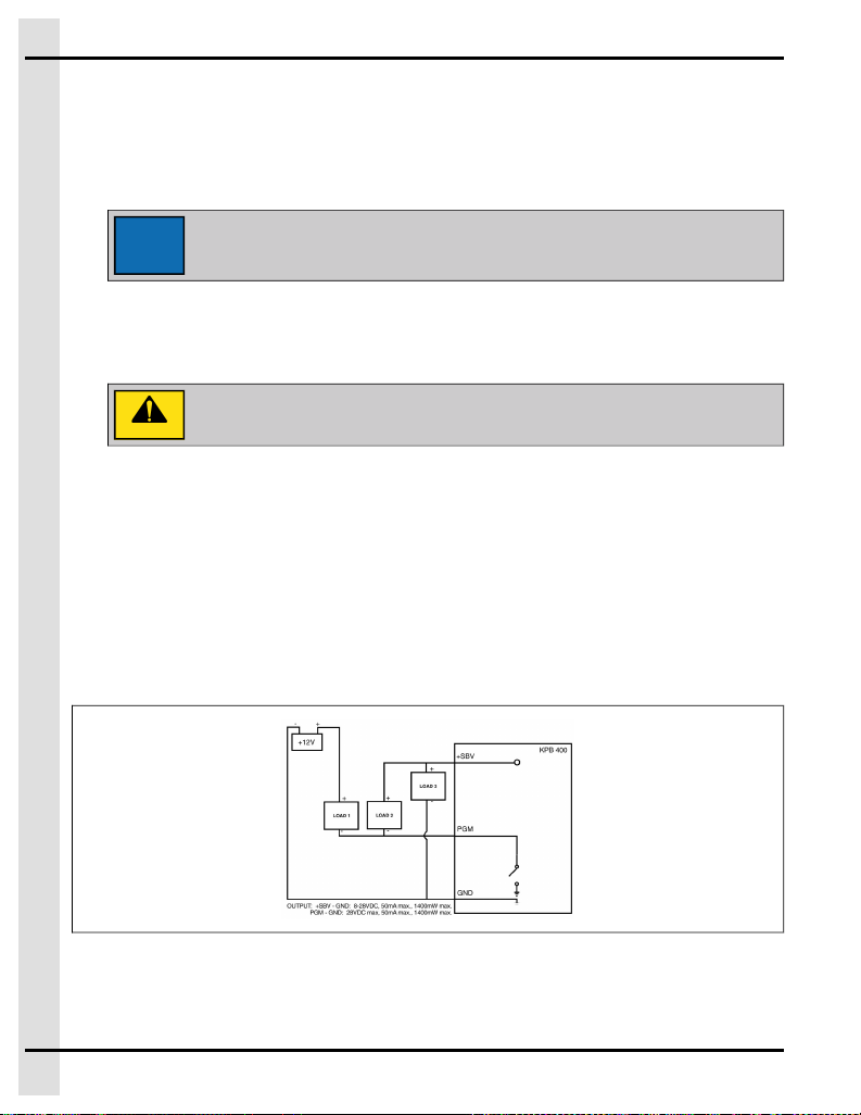
Connecting the Programmable Outputs
The module has an output that can be activated automatically if the system is configured accordingly. The
output can also be activated over the phone or using the keypad.
1. Run a wire from the load’s positive terminal to the positive terminal on the battery.
2. If more than one load is used, run a wire from the other load positive terminals to the +SBV terminal
on the module’s board.
3. Run a wire from the load’s negative terminal to the PGM terminal on the module’s board.
4. Run a wire from the GND terminal to the negative terminal of the battery.
Figure 1-1 Three examples of load connections
10 895-00397 TP-800

Chapitre 1: Connections and Configuration
Setting the End of Line Jumpers
When two or more modules are connected together through the SBI, you must set the end of line (EOL)
jumpers on the electronic card according to the position of the module in the series.
1. Locate the last module of the communication loop, and set the EOL to Yes.
2. Set the EOL jumpers on all other modules to No.
Assigning an Identification Number
1. Once the connections have been made, close the enclosure and apply power to the unit.
The display shows ID 55 which is the default device identification (ID) number.
2. Press the Gear button twice to change the device id number.
The number 2 flashes on the display.
3. Press the button as many times as required to set the ID number.
4. To record the ID number in memory, press and hold the button for 5 seconds.
The ID number stops flashing.
Table 1-1 Display codes
Lz ## Local zone ## has an alarm
Gz ## System zone ## has an alarm
Er Error - contact your dealer. A trouble on a TP800
zone
895-00397 TP-800 11
1Anschlüsse und Konfiguration
Themen
in diesem Kapitel
▪ Montage des Gehäuses
▪ Erdung des Systems
▪ Schaltplan
▪ Zusammenschließen der Module durch die serielle Busschnittstelle
▪ Konfigurieren eines Bereichs
▪ Anschließen der Sensoren
▪ Anschließen der programmierbaren Ausgänge
▪ Einstellen der Abschlussjumper
▪ Zuweisen einer Identifikationsnummer
Montage des Gehäuses
1. Öffnen Sie das Modul mithilfe der Verriegelung an der Unterseite des Gehäuses.
2. Verwenden Sie die nachstehende Vorlage als Leitfaden und montieren Sie das Gehäuse mithilfe der
Schrauben mit 3/16 Zoll Durchmesser an der Wand.
Erdung des Systems
Mit einer ordnungsgemäß geerdeten Einheit werden die Elektronikbauteile vor Schäden durch Blitzein-
schläge und Spannungsspitzen sowie vor elektrostatischer Entladung geschützt. Verwenden Sie die
Erdung nicht zu diesem Zweck.
Was Sie wissen sollten
WICHTIG: Wenn Sie Außenanschlüsse verwenden, montieren Sie das Gehäuse möglichst in der Nähe
der Eingangsstelle der Außenverkabelung.
1. Stecken Sie den sauberen Erdungsstab aus Metall mindestens 3 m (10 Fuß) in den Boden. Wenn
der Untergrund mehr als 1,2 m (47 Zoll) tief ist, stecken Sie den Stab auf Untergrundebene in den
Boden und vergraben Sie den Rest des Stabs waagerecht mindestens 600 mm (2 Fuß) tief im
895-00397 TP-800 7

This equipment shall be installed in accordance with the
current installation codes and applicable regulations
which should be carefully followed in all cases.
Authorities having jurisdiction should be consulted
before installations are made.
www.gsiag.com
Copyright © by GSI Electronics
Printed in Canada
Chapter 1 Anschlüsse und Konfiguration..................................................................................................7
Montage des Gehäuses...............................................................................................................7
Erdung des Systems....................................................................................................................7
Schaltplan...................................................................................................................................8
Zusammenschließen der Module durch die serielle Busschnittstelle ................................................8
Konfigurieren eines Bereichs........................................................................................................9
Anschließen der Sensoren.........................................................................................................10
Anschließen der programmierbaren Ausgänge ............................................................................10
Einstellen der Abschlussjumper..................................................................................................11
Zuweisen einer Identifikationsnummer ........................................................................................ 11
895-00397 TP-800 5

Dieses Gerät muss gemäß den aktuellen
Installationsvorschriften sowie den geltenden
Bestimmungen installiert werden, die in allen Fällen
genauestens eingehalten werden müssen. Vor der
Durchführung von Installationen sollten Sie sich von
entsprechend zuständigen Behörden beraten lassen.
www.gsiag.com
Copyright © by GSI Electronics
Printed in Kanada
User Guide (EN)
Guide de l’utilisateur (FR)
Guía del usuario (ES)
用户指南 (ZH)
Guia do usuário (PT)
Pуководство пользователя (RU)
Anleitung (DE)
890-00596 rev. 00
TP-800
rev. 00


Установка данного оборудования должна
осуществляться в соответствии с существующими
правилами по установке и действующими нормами
(которые необходимо тщательно соблюдать на всех
этапах работы). Перед установкой необходимо
получить соответствующее разрешение у
компетентных органов власти.
www.gsiag.com
© , комп. GSI Electronics Напечатано в Канада
Chapitre 1 Installation.................................................................................................................................5
Mise en place du contrôleur..........................................................................................................5
Mise à la terre .............................................................................................................................5
Diagramme schématique .............................................................................................................6
Brancher les modules ensemble à travers le bus de communication ................................................7
Configurer une zone ....................................................................................................................7
Brancher les sondes....................................................................................................................7
Brancher les sorties programmables .............................................................................................8
Régler les cavaliers de fin de ligne ................................................................................................9
Ajuster le numéro d’identification du TP800 .................................................................................10
895-00397 TP-800 3
Раздел 1: Подключение и настройка
Назначение идентификационного номера
1. Выполнив все подключения, закройте корпус и подайте питание к блоку.
На дисплее отобразится номер ID 55, который является идентификационным (ID) номером
устройства по умолчанию.
2. Нажмите кнопку с шестеренкой два раза, чтобы изменить идентификационный номер
устройства.
На дисплее будет мигать цифра 2.
3. Нажмите кнопку необходимое количество раз, чтобы задать идентификационный номер.
4. Чтобы сохранить идентификационный номер в памяти, нажмите и удерживайте кнопку в
течение 5 секунд.
Идентификационный номер перестанет мигать.
Table 1-1 Коды дисплея
Lz ## В локальной зоне ## сработала сигнализация
Gz ## В системной зоне ## сработала сигнализация
Er Ошибка — обратитесь к дилеру. Проблема в
зоне TP800
12 895-00397 TP-800
1Installation
Sujets abordés dans ce chapitre
▪ Mise en place du contrôleur
▪ Mise à la terre
▪ Diagramme schématique
▪ Brancher les modules ensemble à travers le bus de communication
▪ Configurer une zone
▪ Brancher les sondes
▪ Brancher les sorties programmables
▪ Régler les cavaliers de fin de ligne
▪ Ajuster le numéro d’identification du TP800
Mise en place du contrôleur
1. Ouvrir le TP-800 en tirant sur le loquet situé au bas du boîtier.
2. Fixer le dos du boîtier au mur à l’aide de vis de 3/16” de diamètre.
Mise à la terre
Il est extrêmement important de relier la borne de mise à la terre à une prise de terre convenable pour pro-
téger les composants électroniques des dommages causés par la foudre et les décharges électrostati-
ques. Ne pas utiliser la mise à la terre électrique à cette fin.
Ce qu'il faut savoir
Important
Si des branchements externes sont requis, fixer le boîtier le plus près possible du point
d’entrée du filage externe.
895-00397 TP-800 5

Chapitre 1: Installation
1. Enterrer la tige à une profondeur d’au moins 10 pieds (3 mètres). Si le roc se trouve à 47 pouces (1,2
mètres) ou plus de profondeur, il faut enfoncer la tige jusqu’au roc, et ce qui reste doit être enterré à
une profondeur d’au moins 2 pieds (600 millimètres) sous le niveau du sol fini dans une tranchée
horizontale. Si le roc se trouve à moins de 47 pouces (1,2 mètre), il faut enterrer la tige à une profon-
deur d’au moins 2 pieds (600 millimètres) sous le niveau du sol fini dans une tranchée horizontale.
ATTEN-
TION
La tige doit avoir un diamètre d’au moins 5/8 pouces (1,6 centimètres), doit être
au minimum de 10 pieds (3 mètres) de long et être exempte de peinture, d’émail
ou d’une autre substance peu conductrice.
2. Connecter un conducteur en cuivre, isolé ou nu de calibre 12 AWG au bout de la tige métallique qui
sort du sol.
3. Brancher l’autre bout du conducteur en cuivre, isolé ou nu de calibre 12 AWG au terminal Mise à la
Terre sur la carte maîtresse.
Diagramme schématique
6 895-00397 TP-800
Раздел 1: Подключение и настройка
CAUTION
Убедитесь, что все датчики подключены к соответствующему
терминалу COM. В противном случае возможно ложное срабатывание
аварийной сигнализации.
Подключение программируемых выходов
Модуль оснащен выходом, который может активироваться автоматически при соответствующей
настройке системы. Выход также можно активировать по телефону или с помощью клавиатуры.
1. Соедините кабелем положительную клемму потребителя электроэнергии с положительной
клеммой аккумулятора.
2. При использовании нескольких потребителей электроэнергии соедините кабелем поло-
жительные клеммы других потребителей с терминалом +SBV на плате модуля.
3. Соедините кабелем отрицательную клемму потребителя электроэнергии с терминалом PGM
на плате модуля.
4. Соедините кабелем терминал GND с отрицательной клеммой аккумулятора.
Figure 1-1 Три примера соединения с нагрузкой
Установка концевых перемычек
При соединении двух и более модулей с помощью SBI на электронной плате необходимо устано-
вить концевые перемычки (EOL) в соответствии с расположением модуля в цепи последова-
тельного подключения.
1. Найдите последний модуль коммуникационной цепи и установите EOL в положение Да.
2. Перемычки EOL на всех остальных модулях установите в положение Нет.
895-00397 TP-800 11

Раздел 1: Подключение и настройка
В примере показана настройка шестой зоны в качестве входа 4–20 мА
Подключение датчиков
Before You Begin
Чтобы предотвратить короткое замыкание, при подключении оборудования к прилагаемым терми-
налам зачищать провода следует как можно меньше или не более чем на 7 мм.
Примеры подключения цепей зон с конечным резистором (или двойным конечным резистором) или
без него см. в Приложении B.
1. После подсоединения цепей пропустите провода через отверстия для электрических пре-
дохранителей в днище корпуса.
NOTICE
Запрещается создавать дополнительные отверстия в корпусе. В
противном случае гарантия будет аннулирована без последующего
уведомления.
2. Используйте держатель кабеля, чтобы обеспечить водонепроницаемость блока.
3. Подключите цепь каждого датчика к терминалу Zи терминалу COM.
NOTE: Каждый терминал COM используется двумя зонами. Например, зоны Z1 иZ2
используют один и тот же терминал COM.
10 895-00397 TP-800
Chapitre 1: Installation
Brancher les modules ensemble à travers le bus de communication
Le bus de communication sert à relier les différents modules de l’Agri-Alerte. Chaque module comprend
quatre bornes identifiées Serial Bus Input numérotées de 1 à 4.
1. Utiliser deux paires torsadées blindées. Reliez toutes les bornes n° 1 ensemble, les bornes n° 2
ensemble, et ainsi de suite.
2. Régler le cavalier de fin de ligne (end of line) des modules aux extrémités du fil de communication à
YES.
3. Régler le cavalier de fin de ligne des autres modules à NO.
Configurer une zone
Pour configurer une zone, placer le cavalier correspondant à la position qui correspond au détecteur
utilisé.
Il y a trois positions du cavalier pour chaque zone. La première position (DRY/TEMP) est pour les
contacts secs (normalement fermé ou ouvert, avec ou sans résistance de terminaison simple ou
double) et les sondes de température. La deuxième position est pour les entrées 4- 20mA et la troi-
sième est pour les entrées 0-5V et détecteurs de courant AC. Un seul cavalier est utilisé pour confi-
gurer une zone. Toutes les zones sont initialement configurées en DRY/TEMP. Les numéros des
zones sont imprimés sur la carte. Les cavaliers doivent être délogés avec soin.
Important
si vous ajoutez une résistance de terminaison simple ou double, la résistance de ter-
minaison doit être branchée au détecteur qui est le plus éloigné du TP-800. Dans le
cas d’une résistance de terminaison double, vous pouvez branchez un maximum de
trois zones sur le même circuit.
Exemple de la zone six configurer en zone 4-20mA
Brancher les sondes
Before You Begin
895-00397 TP-800 7

Chapitre 1: Installation
Les fils utilisés pour brancher les équipements aux bornes du TP-800 doivent être dénudés le moins pos-
sible (environ 1/4”) pour éviter les courts-circuits.
Voir annexe A pour des exemples de connexions de circuits de zones avec ou sans résistance de fin de
ligne.
1. Une fois les branchements terminés, passer les fils par les entrées de câbles situées sous le boîtier.
AVIS
La garantie est annulée si des trous additionnels sont perforés dans le boîtier.
2. Brancher chaque détecteur à une borne Zet à la borne COM.
Remarque
Chaque borne COM est utilisée par deux zones : par exemple, Z1 et Z2 utilisent la même
borne COM.
ATTEN-
TION
S’assurer que chaque détecteur est raccordé à la borne COM appropriée. De
fausses alarmes peuvent survenir si les fils sont mal raccordés.
Brancher les sorties programmables
Les modules raccordés à l’Agri-Alerte sont dotés d’une sortie programmable que l’on peut activer à partir
du clavier ou par téléphone, ou encore en cas d’alarme.
1. Faites passer un câble de la borne positive de la charge à la borne positive de la batterie.
2. Si plus d’une charge est utilisée, faites passer un câble de l’autre borne positive à la borne +SBV sur
la carte du module.
3. Faites passer un câble de la borne négative de la charge à la borne PGM sur la carte du module.
4. Faites passer un câble de la borne GND à la borne négative de la batterie.
8 895-00397 TP-800
Раздел 1: Подключение и настройка
Подключение модулей с помощью интерфейса
последовательной шины
Для добавления дополнительных входов в систему Agri-Alert могут использоваться различные типы
модулей. Каждый модуль оснащен четырьмя терминалами, помеченными как Serial Bus Input и
пронумерованными от 1 до 4. Все модули соединяются вместе с помощью интерфейса последова-
тельной шины (SBI).
1. С помощью экранированных кабелей с витой парой соедините два модуля через SBI, соеди-
нив терминалы с одинаковыми номерами.
2. Установите концевую перемычку последнего модуля коммуникационной линии, располо-
женную на верхней плате модуля, в положение ДА.
3. Все остальные концевые перемычки на верхней плате модуля установите в положение НЕТ.
Рекомендации по размеру и длине кабеля см. в Приложении A.
Настройка зоны
Установите перемычку в положение используемого датчика
Для каждой зоны существует три положения перемычки. Первое положение DRY/TEMP (сухой
контакт/температура) предназначено для сухого контакта (обычно замкнут с или без EOLR/
DEOLR (конечный резистор/двойной конечный резистор); обычно разомкнут с или без EOLR/
DEOLR) и входов температурных датчиков. Второе положение предназначено для входов 4–
20 мА, а третье — для входов 0–5 В и датчика переменного тока. Для настройки каждой зоны
используется только одна перемычка. Первоначально все зоны настроены на DRY/TEMP.
Номера зон напечатаны на материнской плате. Соблюдайте осторожность при извлечении
перемычек.
IMPORTANT: При добавлении EOLR в цепь резистор должен подключаться к датчику, распо-
ложенному дальше всех от системы Agri-Alert. При использовании двойного
резистора к одной цепи можно подключить не более трех зон.
895-00397 TP-800 9

Раздел 1: Подключение и настройка
глубина подпочвы менее 1,2 метра, погрузите стержень горизонтально на глубину не менее
600 мм.
CAUTION
Стержень должен быть не менее 1,6 см в диаметре, длиной не менее 3 м,
с неокрашенной поверхностью, без эмалевого покрытия и прочих
непроводящих веществ.
2. Подсоедините к заземляющему стержню медный проводящий кабель 12 калибра AWG, с
изоляцией или без нее.
3. Другой конец медного кабеля 12 калибра AWG, с изоляцией или без нее, подсоедините к тер-
миналу заземления на плате.
принципиальная схема
8 895-00397 TP-800
Chapitre 1: Installation
Figure 1-1 Trois exemples de branchement pour la sortie programmable
Régler les cavaliers de fin de ligne
Lorsque deux modules ou plus sont branchés ensemble à travers le bus de communication, il faut régler
les cavaliers de fin de ligne (EOL) sur la carte électronique en fonction de l’endroit où le module est situé
dans la série.
1. Trouver le dernier module de la série de communication et régler le cavalier de fin de ligne (EOL) à
Yes.
2. Régler les autres cavaliers de fin de ligne à No.
895-00397 TP-800 9

Chapitre 1: Installation
Ajuster le numéro d’identification du TP800
Chaque module branché à l’Agri-Alerte doit avoir un numéro d'identification unique afin d’être branché au
réseau de l’Agri-Alerte.
1. Lorsque les branchements ont été effectués, fermez le boîtier et alimentez l’appareil.
L’affichage devrait indiquer «ID 55», ce qui correspond au numéro d’identification par défaut du
module.
2. Appuyez deux fois sur le bouton de paramètre pour ajuster le numéro d’identification du module.
Le chiffre «2» devrait clignoter à l’affichage.
3. Appuyez sur le bouton le nombre de fois requises pour ajuster le numéro d’identification.
4. Pour terminer l’ajustement et enregistrer le numéro d’identification en mémoire, enfoncez le bouton
et gardez-le enfoncé pendant 5 secondes.
Le numéro d’identification devrait arrêter de clignoter.
Tableau 1-1 Codes d’affichage
Code Signification
Lz ## La zone locale ## est en alarme.
Gz ## La zone ## du système global est en alarme.
Er Erreur - Contacter votre distributeur.
Un problème sur une zone du TP-800
10 895-00397 TP-800
1Подключение и настройка
Темы, рассматриваемые в данном
разделе
▪ Установка корпуса
▪ Заземление системы
▪ принципиальная схема
▪ Подключение модулей с помощью интерфейса последовательной шины
▪ Настройка зоны
▪ Подключение датчиков
▪ Подключение программируемых выходов
▪ Установка концевых перемычек
▪ Назначение идентификационного номера
Установка корпуса
1. Откройте модуль, используя защелку в нижней части корпуса.
2. Руководствуясь приведенной ниже схемой, установите корпус на стене с помощью винтов диа-
метром 3/16 дюйма.
Заземление системы
Правильное заземление устройства обеспечивает защиту электронных компонентов от пов-
реждений, вызванных грозовым перенапряжением, выбросами напряжения и электростатическими
разрядами. Не используйте для этого заземляющее устройство.
What You Should Know
IMPORTANT: При использовании наружного подключения монтировать корпус следует как можно
ближе к точке входа наружных проводов.
1. Погрузите чистый металлический заземляющий стержень в землю на глубину не менее 3
метров. Если глубина подпочвы превышает 1,2 метра, погрузите стержень на уровень
подпочвы, а оставшуюся часть стержня расположите горизонтально на глубине 600 мм. Если
895-00397 TP-800 7

Cet équipement doit être installé conformément aux
codes et règlements en vigueur et doivent être
respectés en tout temps. Les autorités compétentes
doivent être consultées avant d'effectuer l'installation.
1004 E. Illinois St.
Assumption, IL 62510-0020
Phone: 1-217-226-4421
Fax: 1-217-226-4420
www.gsiag.com
Agri-Alerte est une marque de GSI, une marque mondiale de AGCO Corporation.
Droit d'auteur © by GSI Electronics Imprimé en
Оглавление
Содержание
Раздел 1 Подключение и настройка.......................................................................................................7
Установка корпуса .....................................................................................................................7
Заземление системы .................................................................................................................7
принципиальная схема ..............................................................................................................8
Подключение модулей с помощью интерфейса последовательной шины ..................................9
Настройка зоны .........................................................................................................................9
Подключение датчиков ............................................................................................................10
Подключение программируемых выходов................................................................................ 11
Установка концевых перемычек............................................................................................... 11
Назначение идентификационного номера ...............................................................................12
895-00397 TP-800 5
Other manuals for TP-800
1
Table of contents
Other Agri Alert Security System manuals


Popular Security System manuals by other brands


Lutz-Jesco
Lutz-Jesco EASYCON GW operating instructions

Dedicated Micros
Dedicated Micros SD Excel installation guide

American Dynamics
American Dynamics AD2052 System programming

Witura
Witura WT-1010SA User manual and installation instructions

FBII
FBII XL-4B Hookup and installation instructions

Lorex
Lorex SG17LD800 overview


