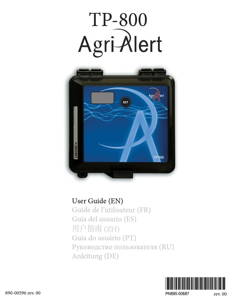
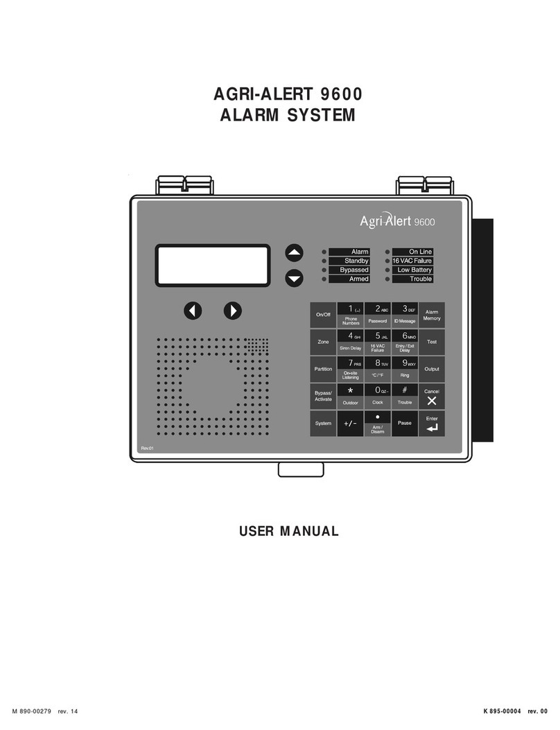
Agri Alert 800 User manual

ALARM SYSTEM
INSTALLATION MANUAL
On / Off
Zone
Partition
Bypass /
Activate
System Pause
Te s t
Alarm
Memory
Contrast
Enter
Outdoor Clock Trouble
Ring
On-site
Listen in
g
Siren Delay Power
Failure
Entry / Exit
Delay
C / F
Cancel
Password
ABC
ID Messa
g
e
DEF
MNO
JKLGHI
PRS TUV W XY
QZ
Arm / Disarm
(...)
M 890-00014 rev. 06 K 895-00002

WARNINGS
The warranty can be void if this product is used in a manner not specified by the manufacturer.
Every effort has been made to ensure that this manual is complete, accurate and up-to-date. The information
contained in it is however subject to change without notice due to further developments.
Manufacturer:
Viatron Electronics
5200, Armand-Frappier
St-Hubert (Quebec)
Canada
J3Z 1G5

3
AA-800 / AA-800T rev.06
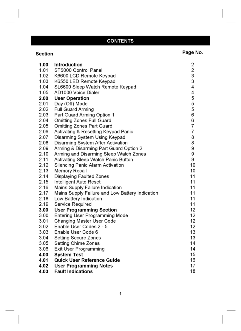
Table of Contents
CHAPTER ONE: INSTALLATION................................................................ 6
1.1 INSTALLATION PROCEDURE .............................................................................. 6
1.2 MOUNTING THE EQUIPMENT ............................................................................ 7
1.3 CONNECTING THE EQUIPMENT ......................................................................... 9
1.3.1 Sensors ............................................................................................... 9
1.3.2 Supply Inputs ..................................................................................... 10
1.3.2.1 AC Power Connection .................................................................... 10
1.3.2.2 Backup Battery Connection ............................................................ 10
1.3.3 Terminal Outputs ................................................................................ 10
1.3.3.1 Siren Output ................................................................................. 10
1.3.3.2 12VDC Output (AA 800T only) ....................................................... 10
1.3.4 Phone Hookup .................................................................................... 11
1.3.5 Connecting the Earth Ground ................................................................ 12
CHAPTER TWO: USER INTERFACE ......................................................... 13
2.1 FRONT PANEL ................................................................................................. 13
2.2 MEANING OF STATUS LEDS ............................................................................. 14
2.3 DISPLAYING A PARAMETER ............................................................................. 14
2.4 MODIFYING A PARAMETER .............................................................................. 15
2.5 HOW TO USE THE MENUS ............................................................................... 16
CHAPTER THREE: SYSTEM INITIALIZATION ............................................. 17
3.1 INSTALLER PASSWORD ................................................................................... 17
3.2 CONFIGURING THE ZONES ...............................................................................18
3.2.1 Dry Contact Input ............................................................................... 21
3.2.2 Dry Contact Burglar Input .................................................................... 24
3.2.3 Temperature Input .............................................................................. 26
3.2.4 Pulse Count Input ................................................................................ 28
3.2.5 Setting the Reset Time ........................................................................ 31
3.2.6 Disable the Siren ................................................................................ 33
3.3 SYSTEM CLOCK ............................................................................................. 34
3.4 USER ID MESSAGE ......................................................................................... 35
3.5 TEMPERATURE UNITS .....................................................................................36
3.6 DISPLAY CONTRAST ....................................................................................... 37
3.7 DEFAULT VALUES ........................................................................................... 38
3.8 TEST PROCEDURE .......................................................................................... 41
3.9 TROUBLE INFORMATION .................................................................................. 41
3.10 VIEWING SOFTWARE VERSION ....................................................................... 42
3.11 STANDBY MODE ...........................................................................................43
CHAPTER FOUR: COMMUNICATION PARAMETERS ................................... 44
4.1 DIALING INFORMATION ................................................................................... 44
4.1.1 Dialing Mode and Speed ...................................................................... 45
4.1.1.1 Dialing Mode ................................................................................ 45

4AA-800 / AA-800T rev.06
4.1.1.2 Tone Dialing Speed ........................................................................ 46
4.1.1.3 Pulse Dialing Speed ....................................................................... 47
4.1.2 Line Seizure ....................................................................................... 50
4.1.3 Call Repetitions .................................................................................. 51
4.1.4 Message Repetitions ........................................................................... 52
4.1.5 Busy Line Tries ................................................................................... 53
4.1.6 Tone Delay ........................................................................................ 54
4.1.7 Pause Delay Key ................................................................................ 55
4.1.8 Call Start Delay .................................................................................. 56
4.1.9 Time Between Calls ............................................................................ 57
4.1.10 Alarm Recall Time ............................................................................. 58
4.1.11 Restore Calls .................................................................................... 59
4.1.12 Disable the Dialer ............................................................................. 60
4.2 PHONE NUMBERS ........................................................................................... 61
4.3 ON SITE LISTENING ......................................................................................... 65
4.4 RINGS / ANSWERING MACHINE ........................................................................ 66
4.5 SYSTEM’S VOICE MUTE ..................................................................................67
CHAPTER FIVE: ALARM PARAMETERS ................................................... 69
5.1 ALARM VALIDATION: SUMMARY OF EVENTS ................................................... 69
5.2 SYSTEM ALARMS ........................................................................................... 70
5.2.1 Backup Battery Voltage Readout .......................................................... 70
5.3 OUTDOOR TEMPERATURE COMPENSATION ON TEMPERATURE ALARMS .............72
5.4 ALARM MEMORY ........................................................................................... 77
5.5 ZONE STATUS DISPLAY ................................................................................... 78
5.5.1 Viewing and Modifying Dry Contact Zones ............................................. 78
5.5.2 Viewing and Modifying Temperature Zones ............................................ 79
5.5.3 Viewing and Modifying Pulse Count Zones ............................................. 82
5.6 PARTITIONS ................................................................................................... 84
5.7 BYPASS / ACTIVATE FUNCTION ....................................................................... 86
5.8 ENTRY DELAY ................................................................................................ 88
5.9 EXIT DELAY .................................................................................................... 89
5.10 SIREN DELAY ................................................................................................ 90
TROUBLESHOOTING GUIDE .................................................................... 91
APPENDIX A: FUSE TYPES .................................................................... 93
APPENDIX B: MAXIMUM WIRE LENGTHS ............................................... 93
APPENDIX C: BACKUP BATTERY LIFE SPAN ............................................ 93
GLOSSARY OF TERMS ........................................................................... 94
WIRING DIAGRAMS ............................................................................... 96
TECHNICAL SPECIFICATIONS ................................................................. 97
REGISTRATION CARD ............................................................................ 99

5
AA-800 / AA-800T rev.06
NOTICE
Every effort has been made to ensure that this manual is complete, accurate and up-
to-date. The information contained in it is however subject to change without notice
due to further developments.
LIST OF TABLES AND FIGURES
Figure 1: Mounting the Enclosures ..................................................................... 7
Figure 2: Location of Mounting Holes ................................................................. 8
Figure 3: Electrical Knockouts for Battery Hookup............................................... 9
Figure 4: Phone Hookup with Line Seizure ........................................................ 11
Figure 5: Phone Hookup without Line Seizure ................................................... 11
Figure 6: Illustration of Recognition Time.......................................................... 19
Figure 7: Normally Open Circuits With EOLR ..................................................... 21
Figure 8: Examples of Zone Connections Without EOLR ..................................... 21
Figure 9: Examples of Zone Connections with EOLR .......................................... 22
Figure 10: Temperature Input ........................................................................... 26
Figure 11: Illustration of Reset Time .................................................................. 31
Figure 12: Pulse Timing Parameters ................................................................... 45
Figure 13: Waiting Time .................................................................................. 54
Figure 14: Calling a Pager Number .................................................................... 64
Figure 15: Outdoor Temperature Compensation .................................................. 72
Figure 16: Critical Temperature Monitoring ........................................................ 73
Figure 17: Monitoring the Indoor-Outdoor Temperature Differences ....................... 73
Figure 18: Example of Partitioning ..................................................................... 84
Table 1: Default Values ................................................................................ 39
Table 2: Pager Codes Used by the Agri-Alert System ........................................ 63
Table 3: System Alarms ................................................................................ 70

6AA-800 / AA-800T rev.06
CHAPTER ONE: INSTALLATION
1.1 INSTALLATION PROCEDURE
What You Need:- Agri-Alert system including independent battery enclosure
- 12VDC / 7.5AH sealed lead acid battery
- 16.5VAC/40VA transformer
TO AVOID ELECTRICAL SHOCKS AND EQUIPMENT DAMAGE, TURN
OFF THE BREAKER ON WHICH IS CONNECTED THE UNIT BEFORE
CONFIGURING THE MAIN BOARD OR MAKING CONNECTIONS TO
THE TERMINALS.
oStep 1: Determine where you want to install the system. You need an
unswitched AC power outlet and a telephone plug nearby to operate the system.
oStep 2: Make a list of all the sensor inputs you will be using with the Agri-Alert
system.
oStep 3: Mount the Agri-Alert system and the battery enclosure on the wall (see
Section 1.2).
oStep 4: Connect a ground wire to the main ground of the system (see Section
1.3.5).
oStep 5: Hook up the sensors, the telephone line and the siren (if used) to the
terminals on the main board in the Agri-Alert enclosure (see Section 1.3).
oStep 6: Hook up the battery (see 1.3.2.2) and plug the transformer into an AC
power outlet.
!
WARNING
!
WARNING
Caution. Carefully read the following text for it contains important infor-
mation which, if ignored, may cause the controller to operate improperly.
Pay attention. The following text contains very useful information.
KEYS TO SYMBOLS IN THE MANUAL

7
AA-800 / AA-800T rev.06
Figure 1: Mounting the Enclosures
1.2 MOUNTING THE EQUIPMENT
The Agri-Alert system should be mounted on a wall as shown in the figure below. The
Agri-Alert enclosure is opened by sliding the latch upwards and pulling. The battery
enclosure is opened by pulling on the latch. Use 3/16” diameter screws to mount
each enclosure on the wall. Fasten the black caps onto the mounting holes once the
screws are tightened. Make sure the covers of the two boxes can be opened easily.
The battery enclosure has ventilation openings on the sides. Make sure they are not
obstructed. Mount the battery enclosure 4” from the Agri-Alert enclosure. Use the
plastic tubing provided to run the wires from the battery to the alarm system. These
wires are provided with the system. The bare end hooks up to the Agri-Alert system.
Electrical knockouts are located on the bottom of each enclosure for running the tube.
Use a screwdriver and a hammer to punch out the holes. Use the cable holders pro-
vided to connect the tube to the enclosure. This prevents water from seeping into the
enclosure.

8AA-800 / AA-800T rev.06
IF OUTDOOR CONNECTIONS ARE USED, MOUNT THE ENCLO-
SURE AS CLOSE AS POSSIBLE TO THE ENTRY POINT OF THE
OUTDOOR WIRING.
!
CAUTION
Figure 2: Location of Mounting Holes
AGRI-ALERT BATTERY

9
AA-800 / AA-800T rev.06
Sensor Inputs on the Main Board:
GNDZ1 Z2 GNDZ3 Z4 Z5 Z6 Z7 Z8
ZONE INPUTS
GND GND
1.3 CONNECTING THE EQUIPMENT
When connecting the equipment to the terminals provided on the main board and the
extension cards, strip the wires as little as possible (about 1/4”) to avoid electrical
shorts. Avoid running wires too close to the heat sink (H5 and H6). Once the wires
are connected, run them through the electrical knockouts provided on the bottom of
the Agri-Alert enclosure and use a cable holder (2 cable holders are provided for the
battery connections and 2 additional cable holders are included with the system —
you can order additional cable holders from your dealer if needed). Additional holes
made in the enclosure will void the warranty.
1.3.1 Sensors
The terminals used for sensor inputs are numbered Z1, Z2, Z3, etc. on the main
board. Connect each sensor to a Z terminal and to the ground terminal (GND). Note
that each ground terminal is used by two zones; for example, Z1 and Z2 use the
same ground. Make sure each sensor is connected to the proper ground. False
alarms can result if the ground wires are not properly connected.
Figure 3: Electrical Knockouts for Battery Hookup
AGRI-ALERT BATTERY
BATTERY HOOK-UP
TUBING
BATTERY
WIRES
TERMINALS

10 AA-800 / AA-800T rev.06
BATTERY
+
SUPPLY INPUTS
-
s
16VAC
s
BLACK
RED
BATTERY
WALL MOUNT
TRANSFORMER
RED
WIRE
(+)
BLACK
WIRE
(—)
1.3.2 Supply Inputs
1.3.2.1 AC Power Connection
The terminals marked 16VAC on the main board are used for connecting the trans-
former. The transformer provided with the system is a 16.5VAC/40VA transformer.
It must be plugged into a 120VAC/60Hz outlet. The F6 and F7 fuses (5A fast blow)
are connected to this input. Make sure the power source is unswitched (i.e. there is
no switch on the power outlet).
1.3.2.2 Backup Battery Connection
The terminals marked BATTERY are used for the backup
battery. The Agri-Alert system uses a 12VDC / 7.5AH
sealed lead acid battery. No other type of battery can
be used. The F28 fuse (5A slow blow) is connected to
this input. The battery wires run through the tube
provided, as shown in Figure 3. Make sure the positive
wire of the battery is connected to the positive terminal.
See Appendix C for normal battery life spans.
1.3.3 Terminal Outputs
1.3.3.1 Siren Output
The terminals marked SIREN are for the siren. The voltage supplied is 12VDC with a
maximum current of 1.5A. Note that the battery must be hooked up if a siren is used.
The F8 fuse (2A slow blow) is connected to this output. Make sure the positive wire
is connected to the positive terminal of the siren. The siren circuit is monitored by the
Agri-Alert system for defects and wire troubles. This may not work properly if the
impedance of the siren is too high. If this is the case,
you can add a 1.5k resistor (1/2W) to the siren circuit
as close to the siren as possible. If no siren is con-
nected, a 1.5k resistor (1/2W) (included with the sys-
tem) must be wired to the siren output.
1.3.3.2 12VDC Output (AA 800T only)
The terminals marked 12VDC provide 12VDC with a maximum
current of 750mA. This can be used to power other accessories
such as temperature controllers. The F4 fuse (1A fast blow) is
connected to this output. In the event of a power failure, the
battery back-up provides 12VDC to this line. Make sure the posi-
tive wire is connected to the positive terminal of your device.
1.5 k
1/2 W
OUTPUTS
12VDC
+-
SIREN
+-

11
AA-800 / AA-800T rev.06
Figure 5: Phone Hookup without Line Seizure
WALL JACK
RT
T
R
PLUG
TIP
RING
THE TIP WIRE IS THE ONE WITH
THE MOST POSITIVE VOLTAGE
READING ON A VOLTMETER
Figure 4: Phone Hookup with Line Seizure
WALL JACK
PLUG
TO ALL PHONE LINES
1
RT
2
3
45
6
7
8
R1
T1
T
R
R
1
T
1
1.3.4 Phone Hookup
Two types of phone hookups are possible. In the simplest case, the Agri-Alert is con-
nected to the phone lines using an ordinary 6 contact phone jack (Canada: CA11; USA:
RJ11). The two wires from the phone line are connected to the LINE terminals marked R
and T. In this configuration, the user has priority over the system when using the phone
line: the system will wait for the line to free up before dialing out.
The best method is to use a line seizure modular jack designed for use with alarm systems
(Canada: CA31A or CA38A; USA: RJ31A or RJ38A). In this case, the system has priority
over other users when dialing out. A line seizure kit is available from your dealer (part
number 70-10212). The connections for this type of plug are shown in the figure below.
This plug disconnects all other phones on the line when dialing out in an emergency. In
order to do this, you must tap the phone line at its point of entry in the building.

12 AA-800 / AA-800T rev.06
IF OUTDOOR CONNECTIONS ARE USED, MOUNT THE ENCLOSURE
AS CLOSE AS POSSIBLE TO THE ENTRY POINT OF THE OUTDOOR
WIRING.
!
CAUTION
AN IMPROPER EARTH GROUND CONNECTION IMMEDIATELY
VOIDS THE SYSTEM WARRANTY WITHOUT FURTHER NOTICE.
!
WARNING
1.3.5 Connecting the Earth Ground
The earth ground terminal provides a ground for the Agri-Alert system. Use a rod at
least 5/8” (1.6cm) in diameter at least 10’ (3m) long. The rod must have a clean
metal surface free of paint, enamel or other non-conducting substances. Drive the
rod at least 10’ (3m) into the ground. If the bedrock is more than 47” (1.2m) deep,
drive the rod into the ground to bedrock level and bury any remainder horizontally at
least 2’ (600mm) below ground level. If the bedrock is less than 47” (1.2m) deep,
bury the rod horizontally at least 2’ (600 mm) below ground level.
(ref. article 10-702, 3d of the Canadian Electricity Code C22.10-99)
Use a CSA certified wire of TEW type or a UL certified wire of type 1015: Green/
yellow, #12AWG, 600V, 105°C insulated wire. We suggest using a Belden #9912
(color code #189) or equivalent.
The rod must be connected to the wire described above. It is recommended to let the
rod going out of the ground to connect it. The rod length must not exceed 50’ (15m).
It is extremely important that the earth ground terminal be connected to
a proper ground to protect the electronic components from damage due
to lightning surges and electrostatic discharges. Do not use the electrical
ground for this purpose.
0
0
0
0
0
0(7$//,&52' %('52&.
0
!
0

13
AA-800 / AA-800T rev.06
CHAPTER TWO: USER INTERFACE
The system displays and prompts for information by using the alphanumeric screen.
The keypad is used for data entry and for enabling and disabling the various system
functions. The speaker on the front panel delivers voice messages. A built-in piezo-
electric warns of illegal entries (3 short beeps) and beeps once when a valid key is
pressed. The integrated microphone on the front panel is used to record the user ID
message and provide on-site listening. The status of some subsystems is displayed
using LEDs on the front panel.
2.1 FRONT PANEL
1 - Display Screen — An alphanumeric display used to provide information and
prompt for inputs.
2 - Cursor Keys — Used to step through menu items during data entry and for delet-
ing the last character entered.
3 - Zone Status LEDs — Off: DISABLED; On: ACTIVATED; Slow Blinking: BYPASSED;
Fast Blinking: ALARM.
4 - Speaker — System identification and alarm messages.
5 - Integrated Microphone — Records the ID message and provides on-site listening
input.
6 - Keypad — User inputs and information requests.
7 - System LEDs — Status of various subsystems (see table on following page).

14 AA-800 / AA-800T rev.06
2.2 MEANING OF STATUS LEDS
2.3 DISPLAYING A PARAMETER
When you select a parameter to input or modify, the system begins by displaying the
current value or status of the parameter. If the message to display is longer than the
size of the window, it will be scrolled to the left. The display pauses at the end of
each screen to allow time to read the message. You can exit prematurely from a
display sequence at any time by pressing the Cancel key. This will place you in
program mode and allow you to modify the parameter values (see next section). To
exit from this function as well, press the Cancel key once again. If a parameter is not
completely defined when you try to display it, the message INCOMPLETE DATA ap-
pears on the screen. This may be an indication that the system will not behave as
expected. If, for example, a zone input is not completely configured, the system will
DELGNINAEM
MRALA
erasnoitidnocmralaeromroenonehwdetavitcasiDELsihT
lenapehtfoedistfelehtnosDELenozlaudividniehT.detceted
.deepshgihtagniknilbtratsmralanisenozehtotgnidnopserroc
ehtsagnolsadegdelwonkcasimralaehtnehwffodenrutsiDELehT
ondnadespalesahemittesereht,stsixeregnolonnoitidnocmrala
.evitcaerasmralarehto
YBDNATS
.edomybdnatsnisimetsystrelAirgAehtnehwdetavitcasiDELsihT
mralarofstupnirosnesehtgnirotinomspotsmetsyseht,edomsihtnI
signirotinomlamronnehwffodenrutsiDELehT.snoitidnoc
.demuser
DESSAPYB
ehT.dessapyberasenozeromroenonehwdetavitcasiDELsihT
otgnidnopserroclenapehtfoedistfelehtnoSDELenozlaudividni
ffodenrutsiDELehT.deepswoltagniknilbtratssenozdessapybeht
.dessapybyltnerrucerasenozonnehw
DEMRA .demrasienozralgrubehtnehwdetavitcasiDELsihT
ENILNO .enilenohpehtsesumetsysehtnehwdetavitcasiDELsihT
CAV61
ERULIAF
CAV61ehtnodetcetedsieruliafrewopanehwdetavitcasiDELsihT
.)remrofsnarttnuomllaw(tiucricylppus
YRETTABWOL .wolsiegatlovyrettabpukcabehtnehwdetavitcasiDELsihT
ELBUORT
:nehwdetavitcasiDELsihT
ehtmorfdeviecerlangisehthtiwstcilfnocnoitarugifnocenoza
rosnes
yrdroerutarepmetanodetcetedsitiucricneporotrohseriwa
.tupniRLOEhtiwtcatnoc
.detcetedsimelborperawtfosa

15
AA-800 / AA-800T rev.06
ENTER NEW DELAY
_ MIN: _ _ SEC
RANGE FROM
(0 .. 5 MIN, 0 .. 59 SEC)
TO MODIFY. . . . . (↵↵
↵↵
↵)
TO QUIT. . . . . . . (X)
not monitor the zone for alarm conditions. Before enabling the system for normal
operation, make sure all parameters are properly defined. In the case of phone num-
bers and zones, the system will display a message every 3 seconds telling the user
which zones and phone numbers are incomplete. To exit from the warning display,
press the Cancel key.
2.4 MODIFYING A PARAMETER
If you have selected a parameter and the display sequence is now finished, you can
begin modifying the parameter values. The following screen appears on the display:
This screen is also displayed if the display sequence described above was cancelled
prematurely. If you want to modify the parameter values at this point, press the Enter
key to modify the parameter. The system will prompt for the information re-
quired to define the parameter. When the parameter is defined by a numerical value,
a range of possible values is displayed. For example, if you select the Exit Delay
parameter followed by MODIFY, the system responds:
The number of spaces provided for input corresponds to the maximum number of
digits allowed. In this example, one space is provided for the minutes and 2 spaces
are provided for the seconds. The cursor positions itself on the first space and blinks
until a digit is entered. If no response is given within 2 minutes, the system will can-
cel the input session and return to the Date/Time display. If more than one value is
required in the same screen (in this example: hours and minutes), press Enter after
entering the first value to step to the following one. To enter a zero value, you cannot
simply press Enter; you must type 0 Enter.

16 AA-800 / AA-800T rev.06
PASSWORD
MASTER
PASSWORD
STATUS
DATE . . . . . . . . . (1)
TIME . . . . . . . . . (2)
If you make a typing mistake, you can backstep using the back arrow key under-
neath the display window before pressing Enter. The cursor will position itself accord-
ingly. You can enter a negative value if this is allowed (for example, a negative tem-
perature value) by pressing the +/- key either before or after the digits.
After entering a value using the numerical keypad, press Enter to register the value.
If the value entered falls outside the permissible range for that parameter, the system
will beep three times and wait for you to modify the input using the back arrow key.
2.5 HOW TO USE THE MENUS
Menus are used to select a parameter or to assign a predetermined value to a param-
eter. If the menu is comprised of only two items, they are displayed on the screen at
once. For example, when you press the Clock key
QZ-
Clock
, followed by Enter to modify,
the following menu appears:
You simply type the number of the item to select that item (no need to press the Enter
key). When more than two menu items are involved, the system will display one item
at a time and allow the user to scroll through the menu using the up and down-arrow
keys . Each menu item is followed by an arrow symbol to locate the current
position in the menu. Once a menu item is selected, other sub-menus may appear to
further define the input. For example, if you press the Password key . After
having entered the master’s password, the following sub-menu appears:
The first menu item is STATUS. The arrow following the item means you are at the
top of the menu. If you press the down-arrow , the second item appears:
The arrows indicate that menu items are to be found above and below the current
item. When you reach the end of the menu, the last item will have an up-arrow . To
select a menu item, press Enter.

17
AA-800 / AA-800T rev.06
CHAPTER THREE: SYSTEM INITIALIZATION
3.1 INSTALLER PASSWORD
The system uses a special installer password to restrict access to certain initialization
functions. This password must be entered when the SYSTEM menu is selected. By
default, the installer password is set to 0801.
To change the installer password:
1. Press the System key . The current revision number of the software program
is displayed. The installer’s password must be entered.
2. Enter the installer’s password (0801 by default) and press Enter .
3. Using the up and down-arrow keys , scroll the menu until the item dis-
played is PRORGRAM AUX’S and press Enter .
4. Using the up and down-arrow keys , scroll the menu until the item dis-
played is INST. PASSWORD and press Enter .
5. Enter a four-digit code and press Enter . The system prompts for the pass-
word a second time.
SOFTWARE
REV. x.xxx
ENTER INSTALLER
PASSWORD: _ _ _ _
SYSTEM
PROGRAM AUX’S
ENTER NEW
PASSWORD: _ _ _ _
PROGRAM AUX’S
INST. PASSWORD

18 AA-800 / AA-800T rev.06
Recognition Time: This is the time an alarm input must be active before it constitutes
a valid alarm condition. It is used to configure all alarm inputs except pulse count and
burglar inputs. Figure 6 below illustrates this. At “A”, an alarm situation occurs when
the temperature exceeds the high set point. At “B”, the temperature returns to nor-
mal. However, only 5 seconds have elapsed and the recognition time is 10 seconds.
Therefore, no alarm occurs. At “C”, a new alarm situation occurs. At “D”, (22 - 12)
= 10 seconds have elapsed; the recognition time has elapsed and an alarm is re-
ported. The recognition time ranges from 0 to 59 hours, 0 to 59 minutes, 0 to 59
seconds. The default is 1 minute on zones 1-8.
6. Re-enter the four-digit code and press Enter . The system saves the new
password and returns to the Program Aux’s scrolling menu.
3.2 CONFIGURING THE ZONES
The Agri-Alert system is a monitoring device used to detect alarm conditions. Differ-
ent types of sensors can be connected to it. When an alarm is detected on any one of
the inputs, the system reports the alarm on-site and starts the dialout sequence. Each
alarm input can be enabled or disabled separately or in conjunction with other inputs.
An alarm stays active until it is acknowledged by a user, either on-site or over the
phone. When an alarm occurs, the system stores all the relevant information: the
number of the input, the type of alarm and the date and time of occurrence. When
the alarm is acknowledged, the system also stores the user who acknowledged the
alarm and the date and time of acknowledgement.
Zone Definition: A zone is an input configured to respond to the type of sensor con-
nected to it. Sensors are installed by the user to detect alarm conditions. The Agri-
Alert system allows up to 8 different zones. The alarm types supported are dry con-
tact, dry contact burglar, temperature and pulse count. A reset time is defined for all
zones. The other parameters apply to each individual zone, i.e. the recognition time,
the siren enable and the dialout sequence enable. The recognition time does not apply
to dry contact burglar zones. In the case of a pulse count alarm, the recognition time
is replaced by a high and low set point and an observation length. If any one of these
parameters is not entered when a zone is configured, the system will display INCOM-
PLETE DATA whenever the parameter definitions are displayed for that zone. Note
that when you reconfigure a zone, the system erases the alarm memory for all zones.
Once a zone is configured, it must be activated by the user to start alarm detection on
that zone. The following parameters are used for defining zones:
ENTER AGAIN:
_ _ _ _

19
AA-800 / AA-800T rev.06
CONFIGURING THE ZONES
1. Press the System key . The current revision number of the software program
is displayed. The installer password must then be entered.
2. Enter the installer password (0801 by default) and press Enter .
3. Press Enter once again to select PROGRAM ZONES.
4. Type the number of the zone to define or modify and press Enter. The current
definitions for this zone are displayed. Default settings for zones are given in Section
3.7. To exit the display function, press Cancel.
Figure 6: Illustration of Recognition Time
High Set Point
Low Set Point
Temperature
Time
AB
D
Alarm
Recognition Time = 10 S
C
0 S 5 S 12 S 22 S
ALARM
NO ALARM
ALARM
SOFTWARE
REV. x.xxx
ENTER INSTALLER
PASSWORD: _ _ _ _
SYSTEM
PROGRAM ZONES
SELECT ZONE
(1 .. 8): _

20 AA-800 / AA-800T rev.06
5. Press Enter to modify the zone or Cancel to exit this function. If the zone selected
is the outdoor probe used for the outdoor temperature compensation feature and the
compensation feature is currently enabled, the system displays the message: DEACTI-
VATE OUTDOOR STATUS. If you want to use the compensation feature, you will
have to assign another probe as the outdoor probe (See Section 5.3). The system
beeps four times and displays the message: WARNING! ALARM MEMORY WILL BE
LOST! Each time a zone is reconfigured, the alarm memory associated with all zone
configurations is erased.
The different types of sensors are presented in a scrolling menu. Use the up and
down arrow keys to select the desired type and press Enter .
The following sections describe the input sequence for each of the sensor types.
TO MODIFY. . . . . (↵↵
↵↵
↵)
TO QUIT. . . . . . . (X)
TYPE OF SENSOR
DRY CONTACT?
This manual suits for next models
1
Table of contents
Other Agri Alert Security System manuals
Popular Security System manuals by other brands
AV Costar
AV Costar ConteraIP MicroDome Duo LX installation manual
Teltonika
Teltonika TWCT22 user manual
ring
ring Alarm manual
Klaxon
Klaxon Nexus 110 AC installation instructions
OneSpan
OneSpan Digipass FIDO Touch user guide

ITALIANA SENSORI
ITALIANA SENSORI 8156-ISS021 Installation, operation and maintenance manual
