Agri Alert 9600 User manual

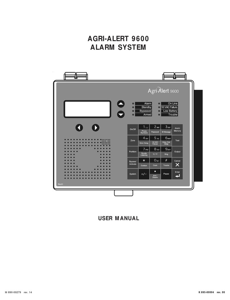
AGRI-ALERT 9600
ALARM SYSTEM
INSTALLATION MANUAL

WARNINGS
The warranty can be void if this product is used in a manner not specified by the manufacturer.
Every effort has been made to ensure that this manual is complete, accurate and up-to-date. The information
contained in it is however subject to change without notice due to further developments.
Manufacturer:
Viatron Electronics
5200, Armand-Frappier
St-Hubert (Quebec)
Canada
J3Z 1G5

TABLE OF CONTENTS
SYSTEM OVERVIEW ................................................................................ 9
CHAPTER ONE: INSTALLATION.............................................................. 11
1.1 INSTALLATION PROCEDURE...................................................................... 11
1.2 CONFIGURING THE SYSTEM...................................................................... 12
1.2.1 Main Board ................................................................................................................ 12
1.2.2 Extension Cards .......................................................................................................... 14
1.3 MOUNTING THE EQUIPMENT ..................................................................... 17
1.4 CONNECTING THE EQUIPMENT.................................................................. 18
1.4.1 Sensors..................................................................................................................... 19
1.4.2 Supply Inputs ............................................................................................................. 19
1.4.2.1 Backup Battery Connection ..................................................................................... 19
1.4.2.2 AC Power Connection ............................................................................................ 19
1.4.3 Terminal Outputs ........................................................................................................ 20
1.4.3.1 0-10V Output ....................................................................................................... 20
1.4.3.2 Siren Output ........................................................................................................ 20
1.4.3.3 12VDC Output ..................................................................................................... 20
1.4.4 External Microphone / Microphone Box Hookup ................................................................. 20
1.4.5 Phone Hookup ............................................................................................................ 22
1.4.6 Programmable Outputs................................................................................................. 23
1.4.7 Connecting the Earth Ground ......................................................................................... 24
1.5 SERIAL BUS INTERFACE CONNECTIONS ..................................................... 25
1.5.1 Connecting Devices to the AA-9600 ............................................................................... 25
1.5.2 End of Line Jumpers .................................................................................................... 25
1.5.3 Connecting a Bridge-A to the AA-9600 ........................................................................... 26
CHAPTER TWO: USER INTERFACE ......................................................... 27
2.1 FRONT PANEL .......................................................................................... 27
2.2 MEANING OF STATUS LEDS ..................................................................... 28
2.3 DISPLAYING A PARAMETER ...................................................................... 28
2.4 MODIFYING A PARAMETER ....................................................................... 29
2.5 HOW TO USE THE MENUS......................................................................... 30
CHAPTER THREE: SYSTEM INITIALIZATION ............................................ 32

4AA-9600.rev.16
3.1 SYSTEM INSTALLATION MENUS................................................................ 32
3.2 EXTENSION CARD INITIALIZATION............................................................. 33
3.3 DEVICE INITIALIZATION ............................................................................ 35
3.3.1 Add Device to Network ................................................................................................ 35
3.3.2 Remove Device from Network ....................................................................................... 37
3.3.3 Edit Device Label ........................................................................................................ 38
3.3.4 Upload Data To/From a UP-1000 ..................................................................................... 40
3.3.5 Upload Data to a Device ................................................................................................ 41
3.3.7 Display Device Information............................................................................................ 43
3.4 ZONE ASSIGNMENTS................................................................................ 44
3.4.1 Manual Assignment ..................................................................................................... 46
3.4.2 Automatic Assignments................................................................................................ 46
3.4.3 Assigning an External Zone........................................................................................... 48
3.5 SBI INITIALIZATION................................................................................... 51
3.5.1 Disable SBI in Case of Low Battery ................................................................................. 51
3.5.2 Adjust SBI Speed ........................................................................................................ 52
3.5.3 Monitor SBI ............................................................................................................... 53
3.6 SYSTEM CLOCK ....................................................................................... 54
3.7 TEMPERATURE UNITS ............................................................................... 55
3.8 DISPLAY CONTRAST................................................................................. 56
3.9 USER ID MESSAGE.................................................................................... 57
3.10 DELETING ALL ID MESSAGES .................................................................. 59
3.11 DEFAULT VALUES.................................................................................. 60
3.12 MONITOR 12VDC OUTPUT ...................................................................... 64
3.13 TESTS ................................................................................................... 65
3.13.1 Test Procedure ......................................................................................................... 65
3.13.2 Advanced SBI Test .................................................................................................... 66
3.14 VIEWING SOFTWARE VERSION ................................................................ 68
3.15 AUTOSCROLL STATUS MENUS................................................................. 69
CHAPTER FOUR: ZONE CONFIGURATION ................................................ 70
4.1 CONFIGURATION...................................................................................... 71
4.1.1 Dry Contact Input ....................................................................................................... 72

5
AA-9600.rev.16
4.1.2 Dry Contact Burglar Input ............................................................................................. 77
4.1.3 Temperature Input ...................................................................................................... 81
4.1.3.1 Calibration of the Temperature Probes....................................................................... 82
4.1.3.2 Configuration of a Temperature Zone ........................................................................ 83
4.1.4 4-20mA Input ............................................................................................................ 87
4.1.5 AC Current Sensor Input ............................................................................................. 90
4.1.6 0-5V Input ................................................................................................................ 93
4.1.7 Disable the Siren ......................................................................................................... 95
4.2 COPYING A ZONE CONFIGURATION TO ANOTHER ZONE ............................. 96
4.3 DISPLAY ZONE INFORMATION................................................................... 97
4.4 EDIT ZONE LABEL..................................................................................... 98
4.5 ZONE ID MESSAGE ................................................................................... 99
4.6 RESET TIME............................................................................................ 101
4.7 MIN/MAX TIME....................................................................................... 103
4.8 DELETING THE ZONES ............................................................................ 104
4.8.1 Deleting Individual Zones ..............................................................................................104
4.8.2 Deleting Devices’ Zones ...............................................................................................105
4.8.3 Deleting All Zones ......................................................................................................106
CHAPTER FIVE: COMMUNICATION PARAMETERS .................................. 107
5.1 CENTRAL ALARM REPORTING CODES ...................................................... 107
5.1.1 Setting the Account Number ......................................................................................108
5.1.2 Setting Alarm Codes for Zones...................................................................................109
5.1.3 Setting Alarm Codes for System Alarms .......................................................................110
5.1.4 Setting Restore Codes for Zones ...................................................................................112
5.1.5 Setting Restore Codes for System Alarms .....................................................................114
5.1.6 Reporting Temperature Readings to Central Alarm Facility ..................................................115
5.1.7 Reporting Zone and Partition Status Changes ...................................................................117
5.1.8 Reporting Speed to the Central Alarm Facility ..................................................................118
5.2 DIALING INFORMATION .......................................................................... 120
5.2.1 Dialing Mode and Speed...............................................................................................121
5.2.1.1 Dialing Mode .......................................................................................................122
5.2.1.2 Tone Dialing Speed ...............................................................................................123
5.2.1.3 Pulse Dialing Speed...............................................................................................124
5.2.2 Line Seizure ..............................................................................................................126
5.2.3 # of Call Repetitions ...................................................................................................127
5.2.4 Message Repetitions ...................................................................................................128
5.2.5 Busy Tries ................................................................................................................129
5.2.6 Tone Delay ...............................................................................................................130
5.2.7 Pause Delay Key ........................................................................................................131
5.2.8 Call Start Delay .........................................................................................................132
5.2.9 Time Between Calls ....................................................................................................133
5.2.10 Alarm Recall Time ....................................................................................................134

6AA-9600.rev.16
5.2.11 Restore Calls ...........................................................................................................135
5.2.12 Disable the Dialer .....................................................................................................136
5.3 PHONE NUMBERS................................................................................... 137
5.3.1 Home ......................................................................................................................138
5.3.2 Cellular ....................................................................................................................138
5.3.3 Beeper .....................................................................................................................139
5.3.4 Pager ......................................................................................................................139
5.3.5 Alarm Report ............................................................................................................142
5.3.6 Test Report...............................................................................................................142
5.4 ON SITE LISTENING ................................................................................ 144
5.5 RINGS / ANSWERING MACHINE ............................................................... 146
5.6 SYSTEM’S VOICE MUTE .......................................................................... 147
5.7 PHONE LINE CUT MONITORING................................................................ 148
CHAPTER SIX: SPECIAL FUNCTIONS .................................................... 150
6.1 TROUBLE INFORMATION .......................................................................... 150
6.2 STANDBY MODE .................................................................................... 151
6.3 EVENT BUFFER....................................................................................... 152
6.4 PROGRAMMABLE OUTPUTS .................................................................... 154
6.4.1 Switched Outputs on the Agri-Alert 9600 .......................................................................154
6.4.2 0-10V Output on the Agri-Alert 9600 ............................................................................156
6.4.3 Switched Outputs on Other Devices...............................................................................156
6.4.4 Assigning a Programmable Output to a Zone ....................................................................158
6.4.5 Removing a Zone Assignment .......................................................................................160
CHAPTER SEVEN: ALARM PARAMETERS .............................................. 161
7.1 ALARM VALIDATION: SUMMARY OF EVENTS .......................................... 161
7.2 SYSTEM ALARMS................................................................................... 162
7.2.1 System Temperature Readout.......................................................................................162
7.2.2 Backup Battery Voltage Readout ...................................................................................163
7.3 OUTDOOR TEMPERATURE COMPENSATION ON TEMPERATURE ALARMS .... 164
7.3.1 To Make an Outdoor Probe Assignment ..........................................................................166
7.3.2 To Activate / Deactivate the Outdoor Temperature Compensation .......................................167
7.3.3 To Set the Offset Temperature .....................................................................................168
7.4 ALARM MEMORY.................................................................................... 169
7.5 ZONE STATUS DISPLAY.......................................................................... 170
7.5.1 Adjusting Set Points ...................................................................................................172
7.5.2 Adjusting Curve Offset Values ......................................................................................173
7.5.3 Adjusting Curve Points .................................................................................................174

7
AA-9600.rev.16
7.5.4 Enabling / Disabling Temperature Curve ..........................................................................175
7.5.5 Adjusting the Recognition Time .....................................................................................176
7.5.6 Copying Zone Set Points to Another Zone .......................................................................176
7.5.7 Resetting Minimum / Maximum Values ............................................................................177
7.6 PARTITIONS ........................................................................................... 178
7.6.1 Adding a zone ...........................................................................................................179
7.6.2 Deleting a zone ..........................................................................................................179
7.6.3 Deleting a partition .....................................................................................................180
7.7 BYPASS / ACTIVATE FUNCTION .............................................................. 181
7.7.1 Changing Zone Status .................................................................................................181
7.7.2 Changing Partition Status ............................................................................................182
7.7.3 Viewing Bypassed Zones...............................................................................................182
7.8 ENTRY DELAY........................................................................................ 183
7.9 EXIT DELAY ........................................................................................... 184
7.10 FORCE ARMING .................................................................................... 185
7.11 SIREN PARAMETERS ............................................................................. 186
7.11.1 Siren Delay .............................................................................................................186
7.11.2 Siren Time On .........................................................................................................187
7.11.3 Siren Monitoring.......................................................................................................188
7.12 AUTO-ARMING OF BURGLAR ZONES ...................................................... 189
7.12.1 Auto-Arming / Disarming Time ....................................................................................189
7.12.2 Auto-Arming Status ..................................................................................................190
TROUBLESHOOTING GUIDE .................................................................. 191
APPENDIX A: MAXIMUM WIRE LENGTHS .............................................. 193
APPENDIX B: BACKUP BATTERY LIFE SPAN .......................................... 194
APPENDIX C: COMMUNICATION CABLE GAUGE AND MAXIMUM LENGTH
RECOMMENDATIONS........................................................................ 195
APPENDIX D: CONTACT ID REPORT AND RESTORE CODES .................... 200
APPENDIX E: EVENT CODES ................................................................ 203
APPENDIX F: SYSTEM KEY MENUS....................................................... 210
GLOSSARY OF TERMS ......................................................................... 211
WIRING DIAGRAMS ............................................................................. 213
TECHNICAL SPECIFICATIONS ............................................................... 215
AA-9600 INSTALLATION GUIDE ........................................................... 216
REGISTRATION CARD .......................................................................... 218

8AA-9600.rev.16
NOTICE
Every effort has been made to ensure that this manual is complete, accurate and up-to-date. The information contained in it
is however subject to change without notice due to further developments.
LIST OF TABLES AND FIGURES
Figure 1: AA9600 Installation Layout ............................................................. 9
Figure 2: Location of the Main Board and Extension Cards ..................................12
Figure 3: Location of Jumpers on Main Board ..................................................13
Figure 4: Jumper Positions on Main Board .......................................................13
Figure 5: Extension Card Configuration ...........................................................14
Figure 6: Location of Connectors for Extension Cards ........................................16
Figure 7: Fastening the Extension Card Onto the Main Board...............................16
Figure 8: Mounting the Enclosures .................................................................17
Figure 9: Location of Mounting Holes .............................................................18
Figure 10: Electrical Knockouts for Battery and Transformer Hookup .....................18
Figure 11: Location of Microphone Jumper on Main Board ...................................21
Figure 12: Phone Hookup with Line Seizure .......................................................22
Figure 13: Phone Hookup without Line Seizure...................................................23
Figure 14: Relay Output Connections (Agri-Alert, Relay Box) ................................23
Figure 15: Location of the End of Line Jumper and the Communication Terminals......25
Figure 16: Example of End of Line Jumper Positions ............................................26
Figure 17: Example of a Zone Assignment ........................................................45
Figure 18: Example of Bridge-A Connection.......................................................48
Figure 19: Illustration of Recognition Time ........................................................71
Figure 20: Normally Open Circuits With EOLR....................................................72
Figure 21: Normally Open Circuits with DEOLR ..................................................72
Figure 23: Examples of Zone Connections with EOLR ..........................................73
Figure 22: Examples of Zone Connections Without EOLR .....................................73
Figure 24: Examples of Zone Connections with DEOLR ........................................74
Figure 25: Typical Application of Burglar Zones..................................................77
Figure 26: Temperature Input.........................................................................81
Figure 27: Temperature Input with Temperature Curve .......................................81
Figure 28: 4-20mA Input...............................................................................87
Figure 29: Typical Connection for 4-20mA Input ................................................87
Figure 30: AC Current Sensor Input ................................................................90
Figure 31: Current Sensors’ Windings ..............................................................90
Figure 32: 0-5V Input ...................................................................................93
Figure 33: Illustration of Reset Time ................................................................92
Figure 34: Pulse Timing Parameters ..............................................................121
Figure 35: Waiting Time..............................................................................130
Figure 36: Calling a Pager Number ................................................................141
Figure 37: Outdoor Temperature Compensation ...............................................164
Figure 38: Critical Temperature Monitoring .....................................................165
Figure 39: Monitoring the Indoor-Outdoor Temperature Difference.......................165
Figure 40: Example of Partitioning.................................................................178
Table 1: Default Values ..............................................................................61
Table 2: Pager Codes Used by the Agri-Alert System .....................................140
Table 3: System Alarms ........................................................................... 162

9
AA-9600.rev.16
SYSTEM OVERVIEW
The Agri-Alert system is a complete alarm detection and management system for
agricultural applications. It can handle up to 96 alarm inputs spread over several
buildings. The following diagram shows how the different components are connected
together.
Figure 1: AA9600 Installation Layout
BRIDGE-A
TO TEMPERATURE
CONTROLLER
NETWORKS

10 AA-9600.rev.16
DEVICE DESCRIPTIONS
The complete system can include up to 98 devices.
AA-9600: the main system with 8 basic zones, two relays and one microphone. Two
extension cards can be added allowing 16 additional zones.
TP-800: a remote extension device that adds 8 zones and a programmable output to
the main system.
KP-400: a keypad for displaying system data from a remote location. Includes 4 dry
contact, burglar or temperature zones and one programmable output.
KPB-400: a dust- and moisture-tight keypad for displaying system data from a remote
location. Includes 4 dry contact, burglar or temperature zones and one programmable
output.
LB-9600: a device containing 96 LEDs for indicating zone status.
BRIDGE: a computer communication device. Allows the user to operate the complete
system from a computer keyboard or modem. Datalogs up to 4 Agri-Alert systems (4
X 96 zones). When used with a Combridge-1 card, the Bridge is compatible with
AgBus, allowing the Agri-Alert to fetch temperature readings from existing controller
networks (see section 3.4.3).
!
WARNING
Caution. Carefully read the following text for it contains important infor-
mation which, if ignored, may cause the controller to operate improperly.
Pay attention. The following text contains very useful information.
KEYS TO SYMBOLS IN THE MANUAL

11
AA-9600.rev.16
CHAPTER ONE: INSTALLATION
1.1 INSTALLATION PROCEDURE
What You Need: - Agri-Alert system including independent battery enclosure
- 12VDC 7.5AH sealed lead acid battery
- a 16VAC/150VA transformer in a separate box
Step 1: Determine where you want to install the system. You need an
unswitched AC power outlet and a telephone plug nearby to operate the system.
Step 2: Make a list of all the sensor inputs you will be using with the Agri-Alert
system.
Step 3: Mount the Agri-Alert system and the battery enclosure on the wall (see
Section 1.3).
Step 4: Configure the main board in the Agri-Alert enclosure according to your
list of sensor inputs (see Section 1.2.1).
Step 5: If you have purchased one or two extension cards with the system,
configure them according to the remainder of the sensor inputs (see Section
1.2.2).
Step 6: Connect a ground wire (see Section 1.4.8).
Step 7: Hook up the sensors assigned to the extension cards to the terminals
provided (see Section 1.2.2).
Step 8: Plug the extension cards into the main board (see Section 1.2.2).
Step 9: Hook up the sensors, the telephone line, the microphone (if needed) and
the siren (if used) to the terminals on the main board in the Agri-Alert enclosure
(see Section 1.4).
Step 10: Hook up the battery (see 1.4.2.1) and plug the transformer into an AC
power outlet.
TO AVOID ELECTRICAL SHOCKS AND EQUIPMENT DAMAGE,
TURN OFF THE BREAKER ON WHICH IS CONNECTED THE UNIT
BEFORE CONFIGURING THE MAIN BOARD OR MAKING CONNEC-
TIONS TO THE TERMINALS.
!
WARNING

12 AA-9600.rev.16
1.2 CONFIGURING THE SYSTEM
Before mounting the Agri-Alert system and making the connections, the system must
be configured to respond to the sensors you will be connecting to it. The main board
is the electronic card located inside the Agri-Alert enclosure. It can handle up to 8
sensor inputs. These inputs are called zones. Each extension card you add to the
main board provides 8 additional zones. Two extension cards can be added for a total
of 24 zones.
Figure 2: Location of the Main Board and Extension Cards
1.2.1 Main Board
Before you configure the zones, you need to determine which sensors you will be
connecting to each board and in what order. Zones are then configured using jumpers.
The diagram on the next page shows the location of the jumpers on the main board.
To configure the extension cards, see Section 1.2.2.
To configure a zone, place the corresponding jumper in the correct position for the
sensor being used. There are three jumper positions for each zone. The first position,
called DRY/TEMP, is for dry contact (normally closed with or without EOLR/DEOLR;
normally open with or without EOLR/DEOLR) and temperature inputs. The second
position is for 4-20MA inputs and the third is for 0-5VOLT and AC current sensor
inputs. Only one jumper is used to configure each zone. Initially, all zones are config-
ured for DRY/TEMP. The zone numbers are printed on the main board. Use caution
when prying the jumpers loose.
MAIN BOARD
(8 ZONES)
(8 ZONES)
(8 ZONES)
EXTENSION CARD #2

13
AA-9600.rev.16
Figure 3: Location of Jumpers on Main Board
For example, to configure Zone 6 as a 4-20mA input, place the black jumper as
shown below:
Figure 4: Jumper Positions on Main Board
ZONE JUMPERS
Example :
Zone 6 is configured as 4-20 mA.

14 AA-9600.rev.16
1.2.2 Extension Cards
The basic Agri-Alert system handles up to 8 different zones or sensor inputs. Up to
two extension cards can be added, each one providing 8 additional zones. Each ex-
tension card plugs into the main board located in the Agri-Alert enclosure. The figure
on the following page shows the configuration of an extension card.
Figure 5: Extension Card Configuration
STEP 1: Identifying the Cards — Before you plug the extension cards into the main
board, you need to configure the zones to correspond to the sensors you will be hook-
ing up to each card. To do this, you must first identify the extension cards. Use the
stickers provided for assigning the cards. Each extension card needs a sticker to
identify the input terminals (Connector Sticker) and a sticker to identify the zones
(Zone Sticker). The location of these stickers is shown on the diagram above. Use the
zone number stickers to identify each individual zone.
STEP 2: Configuring the Zone Jumpers — Each zone is configured by placing a jumper
in the position corresponding to the sensor being used. This must be done before the
extension cards are plugged into the main board. There are three jumper positions for
each zone. The first position, called DRY/TEMP, is for dry contact (normally closed
with or without EOLR/DEOLR; normally open with or without EOLR/DEOLR) and tem-
perature inputs. The second position is for 4-20MA inputs and the third is for 0-5VOLT
CONNECTOR
TO THE MAIN
BOARD
ZONE
STICKER
CONNECTOR
STICKER
INPUT
TERMINALS
EXTENSION
CARD
ZONE
JUMPERS

15
AA-9600.rev.16
and AC current sensor inputs. Only one jumper must be used for each zone. Initially,
all zones are configured for DRY/TEMP. The zone numbers are printed on the sticker.
STEP 3: Hooking up the Sensor Inputs — Before connecting the extension cards into
the main board, hook up the sensor inputs to the input terminals according to the
jumper configurations defined above.
STEP 4: Connecting the Extension Cards — Once the extension cards have been
identified and configured as described above, they can be connected to the main
board. The diagram below shows the location of the connectors on the main board
used for the extension cards.
EXTENSION
CARD #1
GND GND GNDZ9 Z10 Z11 Z12 Z13 Z14 Z15 Z16
Z9 Z10 Z11 Z12 Z13 Z14 Z15 Z16
EXTENSION
CARD #2
GND
GND
GND
GND
Z17
Z18
Z19
Z20
Z21
Z22
Z23
Z24
Z17
Z18
Z19
Z20
Z21
Z22
Z23
Z24
INPUTTERMINALS
ZONE
JUMPERS
ZONESTICKER
CONNECTOR
STICKER
CONNECTORTO
MAINBOARD
EXTENSIONCARD#1
EXTENSIONCARD#2
Z10Z11Z12 Z20 Z21 Z22 Z23Z9
Z14
Z15
Z16
Z24
Z25
Z26
Z27
Z13
Z10Z11 Z12 Z20 Z23Z27Z23Z9
Z14
Z15
Z16
Z24
Z25
Z26
Z27
Z13

16 AA-9600.rev.16
MAIN BOARD
BRACKET
BRACKET
EXTENSION CARD
Figure 6: Location of Connectors for Extension Cards
Once an extension card is firmly plugged into the appropriate connector on the main
board, fasten the extension card securely onto the brackets on the board (see above)
using the two screws provided with the card (Figure 6). Remember to initialize the
extension cards from the keypad once the system is running (see Section 2.2).
Figure 7: Fastening the Extension Card Onto the Main Board
CONNECTOR FOR
EXTENSION CARD #1
CONNECTOR FOR
EXTENSION CARD #2
RIGHT BRACKET FOR
EXTENSION CARD #1
LEFT BRACKET FOR
EXTENSION CARD #1
RIGHT BRACKET FOR
EXTENSION CARD #2
LEFT BRACKET FOR
EXTENSION CARD #2

17
AA-9600.rev.16
1.3 MOUNTING THE EQUIPMENT
The Agri-Alert system should be mounted on a wall as shown in the figure below. The
Agri-Alert enclosures are opened by pulling the latch on the bottom. The battery
enclosure is opened by pulling on the latch. Use 3/16” diameter screws to mount
each enclosure on the wall. Fasten the black caps onto the mounting holes once the
screws are tightened. Make sure the covers of the two boxes can be opened easily.
The battery enclosure has ventilation openings on the sides. Make sure they are not
obstructed. Mount the battery enclosure and the transformer 4½” from the Agri-Alert
enclosure. Use the plastic tubing provided to run the wires from the battery and the
transformer to the alarm system. These wires are provided with the system. The
bare end hooks up to the Agri-Alert system. Electrical knockouts are located on the
bottom of each enclosure for running the tube. Use a screwdriver and a hammer to
punch out the holes. Use the cable holders provided to connect the tube to the enclo-
sure. This prevents water from seeping into the enclosure.
Figure 8: Mounting the Enclosures
TRANSFORMER
BATTERY
CABLE
HOLDERS
CABLE
HOLDERS
TUBING

18 AA-9600.rev.16
Figure 9: Location of Mounting Holes
IF OUTDOOR CONNECTIONS ARE USED, MOUNT THE ENCLOSURE
AS CLOSE AS POSSIBLE TO THE ENTRY POINT OF THE OUTDOOR
WIRING.
!
WARNING
BATTERY
TRANSFORMER
BATTERY HOOKUP
TUBE
BATTERY
WIRES
TUBE
WIRES
AGRI-ALERT
1.4 CONNECTING THE EQUIPMENT
When connecting the equipment to the terminals provided on the main board and the
extension cards, strip the wires as little as possible (about 1/4”) to avoid electrical
shorts. Once the wires are connected, run them through the electrical knockouts
provided on the bottom of the Agri-Alert enclosure and use a cable holder (2 special
cable holders are provided for the battery connections and 2 additional cable holders
are included with the system — you can order additional cable holders from your
dealer if needed). Additional holes made in the enclosure will void the warranty.
Figure 10: Electrical Knockouts for Battery and Transformer Hookup
BATTERY
TRANSFORMER
AGRI-ALERT
9 3/8“
23.8 cm
7 3/8“
18.8 cm

19
AA-9600.rev.16
BATTERY
+
SUPPLY INPUTS
-
s
16VAC
s
BLACKRED
BATTERY
TRANSF.
RED
WIRE
(+)
BLACK
WIRE
(—)
1.4.1 Sensors
The terminals used for sensor inputs are numbered Z1, Z2, Z3, etc. on the main board
and on the extension cards. Connect each sensor to a Z terminal and to the COM
terminal. Note that each COM terminal is used by two zones; for example, Z1 and
Z2 use the same COM. Make sure each sensor is connected to the proper COM.
False alarms can result if the wires are not properly connected.
1.4.2 Supply Inputs
1.4.2.1 Backup Battery Connection
The terminals marked BATTERY are used for the backup battery. The Agri-Alert
system uses a 12VDC/7.5AH sealed lead acid battery. No other type of battery can
be used. The battery wires run through the tube provided, as shown in Figure 10.
Make sure the positive wire of the battery is connected to the positive terminal. See
Appendix B for normal battery life spans.
1.4.2.2 AC Power Connection
MAKE SURE that the Agri-Alert 9600 can operate using
only the battery supply BEFORE connecting the
transformer !
The terminals marked 16VAC on the main board are used for
connecting the transformer. The transformer provided with the
system is a 16VAC/150VA transformer. It must be plugged into
a 120VAC/60Hz outlet. Make sure the power source is
unswitched (i.e. there is no switch on the power outlet).
!
WARN-
ING
Sensor Inputs on the Main Board:
Sensor Inputs on the Extension Cards:
COM
Z1 Z2 COMZ3 Z4 Z5 Z6 Z7 Z8
ZONE INPUTS
COM COM
CARD #1
COMZ9 Z10 COMZ11 Z12 Z13 Z14 Z15 Z16
ZONE INPUTS
COM COM
COMZ17 Z18 COMZ19 Z20 Z21 Z22 Z23 Z24
ZONE INPUTS
COM COM
CARD #2

20 AA-9600.rev.16
1.4.3 Terminal Outputs
1.4.3.1 0-10V Output
Terminals marked 0-10V supply a voltage from 0 to 10V
(25mA max) to an auxiliary device. The voltage can be
manually adjusted from the keyboard.
1.4.3.2 Siren Output
The terminals marked SIREN are for the siren. The volt-
age supplied is 12VDC with a maximum current of 1A.
The sound loudness of the siren should not exceed 120
decibels. Note that the battery must be hooked up if a
siren is used. Make sure the positive wire is connected to the positive terminal of the
siren. The siren circuit is monitored by the Agri-Alert system for defects and wire
troubles. This may not work properly if the impedance of the siren is too high. If this
is the case, you can add a 1.5k resistor (1/2W) to the siren circuit as close to the
siren as possible. If no siren is connected, connect a 1.5k resistor (1/2W) (included
with the system) to the siren output or disable siren monitoring (see 7.10.3).
1.4.3.3 12VDC Output
The terminals marked 12VDC provide 12VDC with a maximum current of 750mA.
This can be used to power other accessories such as temperature controllers. In the
event of a power failure, the battery backup provides 12VDC to this line. Make sure
the positive wire is connected to the positive terminal of your device.
1.4.4 External Microphone / Microphone Box Hookup
An external microphone or a microphone box can be hooked up for use with the on-
site listening function (see your dealer). If neither is needed, the system uses a built-
in internal microphone.
A jumper is provided on the main board for configuring the type of microphone used
for on-site listening. If neither the external microphone nor the microphone box is
needed, the jumper can be positioned at either position. Figure 11 shows the location
of the microphone jumper. Use caution when prying the jumper loose. Make sure the
jumper is placed horizontally on the top or bottom pins. Any other positions will lead
to poor results.
External Microphone Hookup – The SHIELD terminal is connected to the wire shield-
ing. The SIGNAL and CASE terminals are connected to the microphone. The AUX
terminal is not used.
0-10V
+
OUTPUTS
-SIREN
+-12VDC
+-
1.5 kOhms
1/2 W
Other manuals for 9600
2
Table of contents
Other Agri Alert Security System manuals
Popular Security System manuals by other brands
Black Widow Security
Black Widow Security BW RAS 130 installation manual
Pyronix
Pyronix ENFORCER V11 Programming guide

Hunt Electronic
Hunt Electronic HDR-16EP user manual

Texecom
Texecom Premier Elite 8XP-W installation manual
Sygonix
Sygonix 1486623 operating instructions

FireAngel
FireAngel WFSVP-629 user manual
