Mount Mount
4858
5- After completing the electricity and battery
connections, place the transparent protection
cover as shown on Figure 5.
Mount optionally provided metal cover as shown
on Figure 7
Mounting the Metal Cover
Figure 5
A
A
B
B
M
Place the ‘A’ nails as they would fit into the ‘B’
holes as shown on Figure 6 and then make the
attached to ‘M’ point by pressing to the top
cover.
As shown on Figure 6 push the ‘M’ latch with a
straight screw driver to upwards and lift the top
cover. Again push the top cover upwards to let
the ‘A’ nails release and remove the top cover.
Attaching the Top Cover
Opening The Top Cover After Mounting
Figure 6
Figure 7
Card Placement
Buzzer
Mi ro switchc
JP1
+12V-
SAB
S
Sounder Trigger
Tamper
-
+
12VDC
JP4
JP2
Battery
Function
Supply type
Starting delay
Sounder time
Jumper
JP 1
JP 2
JP 4
Short
5min.
Open
SCB Mode
is active
5min.
15 min.
FACTORY DEFAULTS
JP 1 : OPEN
JP 2: OPEN
JP 4: SHORT
4- Before to set the electricity connections of the card as shown in Figure 4 take off the JP2 and wait 5
minutes for activating the ‘Starting Delay’ so that during the connection prevented the unnecessary
working possibilities and then complete the electrical connection just same as Figure 4.
After electrical connection during the normal conditions if you do not want ‘Starting Delay’ please take
on the .JP2
Figure 4
AS 260 sounder works with negative trigger. Please adjust
the panel properly. Sample of the connections can see on
Page 6/ Figure 8.
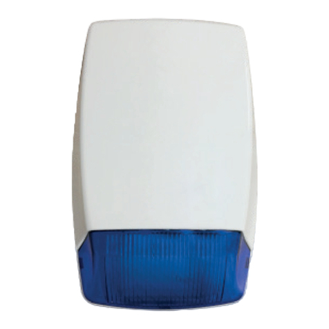
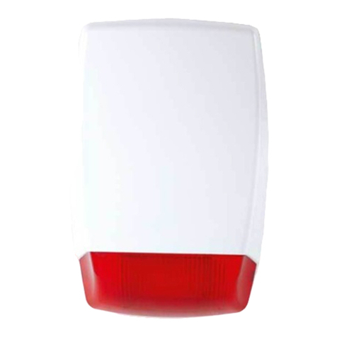
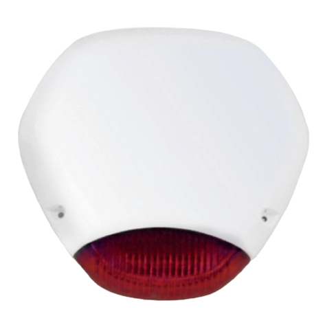
AS 260 AS 260
OUTDOOR SOUNDER OUTDOOR SOUNDER
Important Mounting Notes
1- It should be at least 5 cm below the ceiling in order to be able to open the top cover during assembly.
2- Choose a clean and smooth surface for easy mounting.
3- Use 4 units of M4 52 metal screw and M8 plastic screw holder in-wall*.
SCB Mode: In this mode the unit draws the the majority of
its sounding current from the built-in battery. In this mode
volume is reduced.
None
None


