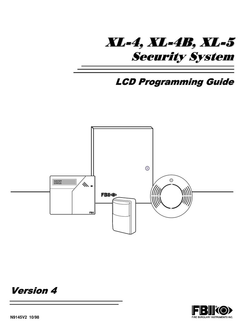
FBII XL-4B User manual

XL-4, XL-4B
Hookup and Installation Instructions
FBmli@>
FIRE BURGWRY INSTRUMENTS, INC.
ASubsidia~ of Htiay COW.
149 Hleen Way, Syoaaet, NY 11791
(800) 645-5430- (516) 921-8666 N9144
Rev
Previous

XL-4 XL-4B TABLE OF CONTENTS
CHAPTER 1. INTRODUCTION .............................3
CHAPTER 2. HOW TO USE THIS MANUAL ........ 4
CHAPTER 3. SYSTEM COMPONENTS ..............5
CHAPTER 4. SYSTEM HOOKUP&WIRING .....6
4.1 Wiring Diagram .......................................6
4.2 Zone Hookup ... .......... .... ..... ...............8
4.3 Hardwired Zone Expander ..................... 6
4.4 MuNplex Zone Expander . .... .............. 9
4.5 Keypad Connections ............................. 10
4.6 Auxiliary Power ....................................12
4.7 Programmer Connection .... . .. .... .. 12
4.8JP1 .......................................................l2
4.9 JP2 ....................................................... 12
4.10 Default Reset ..,,.................................12
4.11 Panel Reset ... .... .... .... .... .... ... 13
4.12 Ground Stan ..... .................. ..... .... .. 13
4.13 Line Seizure .......................................13
4.14 Ground .,,............................................l3
4.15 Telephone Line .. ...... ........ ................ 13
4.16 Tamper Swtch .,,..............................13
4.17 Relay#l .............................................14
4.16 Relay W... .. ......... .............. ............. 15
4.18.1 Smoke Detecfor Reaet ...............l5
4,16.2 DWContacts 16
4.19 Trigger Connector 18
4,20 Transformer .,.,.............................17
4.21 Baffery Backup.............................. 17
4.22 Keypad mounting 17
CHAPTER 5. Muftiplex Polilng Loop
5.1 Multiplex Pelting Loop Ovewiew ....,.19
5.2 MuMplex Expander Installation ........20
CHAPTER 6. SYSTEM OPERATIONS ..............22
6.1 Keypad Layout ...................................... 22
6.2 Sample LCD Display.............................23
6,3 Keypad Function Keys .......................... 23
6.4 Arming the System ................................ 24
6.5 STAY..................................................... 25
6.6 Instant ................................................... 26
6.7 Instant- Stay .......................................... 26
6.6 Bypasa .................................................. 28
6.9 Forced Arming .......... ..... ..................... 27
6.10 Unbypass ............................................ 27
6.11 GmUPS................................................ 26
6.12 Group Bypass ..................................... 26
6.13 Group Unbypaes ................................. 29
6.14 User Programming ..............................29
6.15 User Deletion ........ ...... .....................30
6.16 Disarming ............................................30
6.17 Keypad Emergency Conditions ..........31
6.16Duress .................................................32
6.19 LCD Keypad Programming .................32
6.20 Quick Commands ...............................32
8.20.1 Multi-parfifion [#O] .....................32
6.20.2 Quick Arming [#l] .....................33
6.20.3 Quick Forced Arming [W] .........33
6.20.4 ~me/Date Set[#3] .................... 34
6.20.5 Zone Directory [#4] ...................34
6.20.6 Quick Bypassing [#5] ................35
6,20.7 Chime Mode[#6] ......................35
6.20.8 Parfiiion assignment [#~ ..........35
6.21 LOG DUMP FUNCTION .....................36
6.21.1 Remote Printer............................36
6.21.2 Loml Printer ................................36
6.22 Keypad Function Summary .................37
CHAPTER-71NSTALLERFUNCTIONS............ 36
7.1 Keypad Programming ..........................36
7.2 Time Date Setup .................................. 38
7.3 Walk TeS ............................................. 38
7,4 Walk Test wfih Bell ..... .......................39
7.5 Default Reset .......................................39
7,6 Syefem Log Waw .................................40
FCC Statement .. ........................................42
Nmfiafion of Alarm System ......................... 43
Limited Warran~., .......................................M
I
XL-4HOOKUP &tNSTALLAT10N Page2

1. INTRODUCTION
The XL-4 Series Control-Commmunicstor is afully programmable device with remote
mmmunication and control capabilities, The panel contains 8hardwired zones located on the main
control panel with mutiplex and hardwired expansion capabihties. The expansion options include:
.8zone hatilre expansion (through 7105 module), providing atotal of
16 hardwired zones, or
.Mutiplex pelting loop expansion (through7120 module), providing two
wire mutiplex loop of 64 zones (total system capacity of 72 zones)
The XL4 system can al~ be setup in apatiioned configuration. Partitioning allows the panel
to took like as many as eight different protected lo~fions to the Central Station, Each partiiin will
be assigned zones, users and keypads. The amunt numbers transmitted for each parftion are
definable. Partitions can be setup to protect different functional areas of the same lo~tiin (example,
*area vs. warehouse) or dtierent premises within close proximity (example, shopping center
or muffi family complex).
The system afso contains an event log which stores the paat 128 events intime stamped o~er. This
event @can be viewed by the installer at an LCD keypad, retrieved remotely from the PC
bWnfOSdiW wftware or automatically transmitted to aremote printer at aspectied time.
Programming of the XL4 panel can be accomplished either through the LCD keypad locally, or
remote~ from the Alarm Company location using the =-MATE PC Based Downloader. In a~iion,
remote operations can be petiormed.
Fallura to connect and program the sontml unit aa deecrlbad [n thla manual
Is avlolatlon of tha Lletbsg Mark. Programming r~ulrementa are contained
In the XL-4 LCD Keypad Pmgrammlng manual.
UL LIS~NGS
The XL4 isthe Residential (Household) version of the has been fisted by Undenvfters Laboratories
for the folbwing applications
UL 1023 Household Burglar
UL 985 Household Hre Warning
The mdel XL-4B is the Commercial Burgla~ configuration of the control panel and has been fisted
by Underwrite Laboratories for the following apphcations;
UL 365 Pohce Connected Burglar (Grade AMercantile, Grade B)
UL 609 Local Burglar (Grade AMercantile, Grade B)
UL1610 Central Station Burglar (Grade B, Grade C)
UL 1635 Mgital Burglar
XL-4 HOOKUP &lN=ALLA~ON Page 3

2. HOW TO USE THIS MANUAL
The ~-4 l~n Inatmction Manual has been organked into the following sectiina;
Chapter 1: lNTRODUCTfON
Describes the basic features and capabilities of the XL-4 panel.
Chapter 2: HOW TO USE THE MANUAL
=plains the sections of the Installation Instmcfions.
Chepter 3SYSTEM COMPONENTS
Specfles the compnerrta and accessories available wkh the XL-4.
Chepter 4: SYSTEM HOOKUP AND WIRING
Wring d~ram and installation instmctiona for the control panel.
~apter 5: MULTIPLEX POLLING LOOP
Deacrbea the fundons of the mutiplex polfing loop.
~apter 6. SYSTEM OPERATIONS
Describes the operational procedures as performed through the LCD and LED keypads.
ChaDter 7. INSTALLER FUNCTIONS
Defines the keypad commands resewed for installers during the installation and troubleshooting
of the control panel.
2.1. REMTED DOCUMENTATION
XL-4 LCD KEYPAD PROGRAMMING MANUAL
Detailed manual describing the mmplete programming of an XL4 panel through the LCD keypad.
This manual describes and explains all of the programmable parameters of the XL4.
OWNERS MANUAL
Booklet designed for the end user to describe how to uae the XL-4. Ttis manual rovers bth the
LED and LCD keypads.
XL-4 HOOKUP &INSTALLATION Page 4

3. SYSTEM COMPONENTS
CONTROL PANELS
XL-4
XL-4B
XL-4. Includes 8zone contro~mmmunicator and transformer. Household Burglary and Hre
Version of the XL-4 system. Keypads available separately.
XL-4 for U.L. Mercantile Applications. Contains control panel, transformer, and attack proof
encloeure euitable for UL commercial installations. Keypads available separately.
KEYPADS
7m
7WL
7015
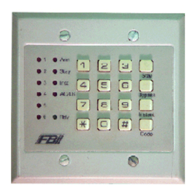
LCD Keypad, two fineby sixteen character English language dsplay, for XL-4. Upto 8LCD
keypads can be used per eystem.
LCD Keypad featuring large character LCD display.
LED Keypad with separate zone indicator hghtsfor the XL-4. Up to 8LED keypads can be
used per system. Note: This keypad can only be used in systems with zone numlbers less
than 16.
EXPANSION MODULES
71W Zone Expander. Plug in mdule provides an additional eight hardwired zones for the XL-4.
7120 MuKiplex Expansion Module. Plug in module provides expansion cape~~iy of 64 zones on
two wire pelting loop hue,
7120 Serial Interface Module. Used to connect aserial printer (300 Baud) for the pupse of
outputing the system log to alocal sedal printer.
ACCESSORIES
71OSUL Trigger cable assembly to interface to the XL-4 vokage level trigger outputs.
7700 EZ-Mate PC Downloader. Software written for IBM or compatible personal computers
(requires ahard drive) and a Hayes 1200 Smartmodem. Providee database maintenance
and remote mmmunications with the XL-4. Note: The downloading software has not been
investigated by Unde~riters Laboratories Inc.
MULTIPLEX PERIPHERALS
XL-4702 2Point Multiplex Adapter Module, allows two conventional alarm seneing devicss to be
wnnecfed to the mutiplex bus,
XL-4708 8Point MuMplex Adapter mdule. Used to intetiace 8conventional sensing devices to the
mutiplex bus. Each point will contain aunique address.
XL-4722 Dual element Passive with bui~ in mu~plex point.
NOTE: The XL-4 mutiplex capability will only operate with fire Burglary Instruments multiplex
accessories.
XL-4 HOOK~JP&INSTALLATION Page 5

I
4. SYSTEM WIRING AND HOOKUP
4.1. WIRING DIAGRAM
nstructions
NOTE 1: Connect to cold water piW
ground. IG gauae al 15 feet.
NOTE 2Terminal &27 is infernally
connectd to teminal #31. For drnntact
Y
output on RELAY #1, cut jumper P2.
NOTE 3: Totil alum current for RELAY 1 a
2i? 2Amps maximum (1 Amp U,L.)
NOTE 4:
a) RELAY #2 can be used to RESET
SMOKE DETECTOR POWER (and fire
vetilicauon). If so, connect ajum~r lmnl
lerminal 33 (+) to terminal 24. Smoke
detector Fewer is defived from terminal 25
(+) a~d 26(-). Also see de!ail A,
in’an alarm o: trouble rnndbi on,or~or alarm
?ower 2by inshlling a‘umper from !eminal
i
31 !+.) to !erminal 24, lam power2 will b
defiled from terminal 23 (+) and 26 (-).
To reioad factor default values,
‘$
retnove til power rom sstem (AC 8
DC! then shod TPI to T2, w,th shoe still
in~ct :eapply pwer (AC then DC), wait 10
$econos then remove short while still
powerti.
TO teset mntrol panel shod TP2 to TP3.
For !ti!ther i“forma! ion cons”[t the
Instruction Manuais.
———.—.
TRANSFORMER
16,5VAC 40VA
Wdel 1361
1+1.
(2W WUL)
[.1.
[+1. AUX WWR
12 .12.8VW *—
lmw k.
[1.(lw WUL)
[+1. ALARM PO~R
12Vw Rw.
mx. 2Amps
[.1. (1hp U,L.)
XL-4 HOOKUP &INSTALLATION Paga 6

XL-4
CONNECTIONS FOR HOUSEHOLD FIRBBURGLAR ALARM SYSTEMS UL985 AND 1023
Ic~TROLPANEL ~
‘w
25 26
I
I
I
I8
,-,, ,5,2,4A ~EL ES,,,,,,
!‘0” “u’
Io}
LISTED
1; HEAT
.-,.,0,,
WARNING
_DISCONNECTPHONELINESPRIORTOSERVICING.
IWARNING
ICAUTION:
IInccr=tcon”coons may res”l$Indmage lo ma unit.
XL-4B
CONNECTIONS FOR HOUSEt~OLD FIRE/BURGLAR ALARM SYSTEMS UL985 AND 1023
,.,.,-,.,.,”,-.,,.... .-,—....—,
mm . . . mnnan, he tin, fem., !. a,emn&de mntolled
WARNING
DISCONNECTPHONELINESPRIOR1OSERVICING
WARNING
THIS UNIT INCLUDES AN AmRhl VERIFICA11ON
FEATURE THAT WILL RESULT IN A3EI AY OF THE
SYSTEM AURM SIGNAL FROM 114E INDICATED
CIRCUITS. TI<E ToTAL DEWY [CO fdTROL UNIT P1.US
SMOKE DETECTOR SHALL NO1 EXCEED 60
k
SECONDS, NO 01 HE INITIATING UEV!CES SH}\LL
BE CONNECTED TO THESE CIF{CU ITS UNLESS
APVAOVED BY TtiE LOCAL AU7b+0RlIy HAVING
JURISDICTION SMOKE D,,,.,.,
...”., CO.mo,.,, r
,,”.,) OEMY. SEC. EODEL DEIAYSEC:
___ -— —— . . .
XL-4 HOOKUP &INSTALLATION MANUAL Page 7

—I
4.2. ZONE HOOKUP
The first eight zones are connected to TI through TI 2 on the main circuif board as folbws;
Zone 1Teminal 1&2(-)
Zone 2Teminal 3&2~)
Zone 3Terminal 4&5(-)
Zone 4Terminal 6&5(-)
Zone 5Terminal 7&8(-)
Zone 6Terminal 9&8(-)
Zone 7Terminal 10& 11 (-)
Zone 8Terminal 12& 11 (-)
XL-4 zones on the main circuit had and through the zone expander should be supawisad using
the 2.2K end of tine resistors suppked. NOTE: fire zones must use Listed pati number EOL22 end
of hne resistom.
4.3. HARDWIRED ZONE EXPANDER (Optional)
The optional Zone Expander Module model 7105 providee an addtional eight zones to the XL-4
mntrol panel. NOTE: Hther the 7105 expander or the 7120 expander can be installed in any XL-4
system. The 7105 zone expander can be installed as follow&
0
1.
1- Remove all Wwer from the XL-4 board.
2- Attach the three plastic suppoti mounting
pieces to the zone expander module in the three
holes located on the printed circuit board.
3- Attach the zone expander to the XL-4 control
board through the plug in connections hated to
the left of the wiring diagram. Carefully ahgn the
six pins on tha top and bottom of the munfing
connectors. Press down firmly on the expander
bOa~ to insure that the board is secure in hth
connectors.
NOTE: Inoderforthe XL-4 to re~gnize the zone
expander the appropriate programming option
enabhng 16 zone operation must be turned on.
This can be accomplished through the LCD
keypad programming sequence or the EZ-Mate
PC Downloader. The sewnd eight zones are
connacted to T38 through T49 on the zone
expsnder as follows;
tine 9Temhd 3S&39
tine 10 Temtid 39 &40
%ne 11 Temhd 41 &42
tine 12 Temti 42 &43
hne 13 Temhd 44 &45
tine 14 Temhd 45 &46
fine 15 Temhd 47 &48
=ne 16 Temtid 48 &49
XL-4 HOOKUP &INSTALLATION Page 8

4.4. MULTIPLEX ZONE EXPANDER
The 7120 Mutiplex expander mdule providee multiplex loop expansion to the control panel.
Each mltiplex loop coneiete of atwo wire hookup which transmits power and data from the control
panel to the mutiplex accessories. The mutiplex expander can be installed as follows;
1- Remove all power from the control panel.
2- Attach the three plastic support mounting pieces to the multiplex expander module in the three
holes located on the printed circuit board of the muhiplex expander, Place the pointed end through
the httom of the mutiplex expander.
3- Mach the mutiplex expander to the wntrol panel through the plug in connections located to the
left of the wiring diagram. Carefully aflgn the eix pins on the top and bottom of the munting
mnnecfora. Press down firmly on the expander board to insure that the board is secure in bth
connectors.
NOTE: In order for the mntrol panel recognize the multiplex expander the programming option
enabting mutiplex operation must be turned on. This can be pefiormed through the keypad
programming sequence or through the EZ-Mate PC Downloading software. Consult the appropriate
manuale to determine the method to enable the muMplex capability.
The mutiplex bus can be connected as follows:
LPI (-) Multiplex Loop (-)
LP1 (+) Multiplex Loop (+)
NOTE: Proper ~lar”~ of the mutiplex bus must be maintained.
XL-4 HOOKUP &INSTALLATION Page 9

4.5. KEYPAD CONNECTIONS
The keypads are wnnected to the mnfrol panel wtih four ~nduaforcable to terminals 13through
16. Attach each keypad used witMn the sySem to the terminsla as follows;
T13 Red (+voifage)
TI 4Green
T15 Yellow
T16 Black ( - vohage)
The following rules apply mncerning ke~ad wiring using 22 AWG wire:
A) Maximum keypad wire runs shall not exceed 1500 feet (any single keypad).
B) Daisy chain sum of keypad runs shall not exceed 3000 feet. This is the sum of the distanoss
!0 all keypads from the mntrol panel on one daisy chain branch. For example, Hone keWad is 750
feet from the panel and another keypad ia 500 feet from the first keypad, then this distance woukt
equal 750 +(750 +500) =2000 feet. Note that mle Astill apphes.
C) Total sum of all single runs and daisy chains shall not exceed 4000 feet. Note that roles A &
Bstill apply. For example, fthere are two single keypad wire runs each 1000 feet from the mntrol
panel, plus the daisy chain ~xample from mle B, the sum of these wire runs would equal 4000 feet.
D) If any keypads are powered from sourws other than the mntrol panel, then acommon ground
must be sonne~ed between terminal 16 and the ground (negative) of the external pwer supply.
E) KeWad wires should be run avoiding sources of possible AC induti}on or inteflerenw mused
by other devices. For example, Electrical wiring, Computer wires, etc...
The available keypad power (from terminals 13 and 16) is restricted to 280 MA (250 MA for UL
apphcations). Each keypad draws approximately 70 mA and therefore amaximum of 4keypads can
obtain power from these connections. Addtional keypads must obtain their power from the other
auxitiary panel outputs of sufficient capacity is available) or an external power supply. Note: Afl
keypads must be conneoted to terminals 14 and 15 regardless of where they obtain power,
XL-4 HOOKUP &INSTALLATION Page 10

Both versions of keypads (LED model7105 and LCD mdel 7005) contain switches ‘1oset the
address of the keypad. TNs address will idetitiy the keypad number to the control panel. In a
parftioned system each keypad can be assigned to apatiiion.
Within the XL-4 programming questions the LED keypads are known as keypads 1-13and the
LCD keypads are known as 9-16.
Theee switches are located behind the pull open door and zone card as shown below;
The first three swtiches (SWI -SW3) should be set as follows;
KEYPAD NUMBER Swl SW2 SW3
mm
19ON ON ON
2 10 OFF ON ON
3 11 ON OFF ON
4 12 OFF OFF ON
513 ON ON OFF
6 14 OFF ON OFF
7 15 ON OFF OFF
6 16 OFF OFF OFF
When the right hand side of the switch is puehed the switch is on the ON ~sition. When the swtich
is Wshed to the left kis inthe OFF Wsifion.
The system should a~ays be pcwered down and when changing dip switches or hooking up
keypade.
NOTE: Keypads of the same type should not be set with the identical addresses, The keypads need
to beenabled wtihin the programming sequence. The XL-4 sup~rfs upto sixteen keypads consisting
of eight LED and eight LCD keypads. NOTE: LED keypads can only be utilized on systems with zone
numbers less than 16 zones.
The facfoy defauti settings enable the first two LCD keypads within the system. At least one LCD
keypad will be necessa~ to petiorm keypad programming.
XL-4 HOOKUP &INSTALLATION MANUAL Page 11

SWITCH 4. KEYPAD SOUNDER
Enables or disables the keypad sounder. Inthe OFF ~sfklonthe keypad sounder will beaotlve.
In the ON postion the keypad will only sound indicating the depression of keys.
NOTE: For U,L. aDDlicationsthe kewad sounder MUST be enabled,
This switch Is only read upon exh from ths ksypad programming sequence.
Therefore to change the keypad eounder wtus set the switch (SW4) to the
desired posltlon then enter and exft from the ksypad programming mode,
4.6. AUXILIARYPOWR
AuxiHaryWwer(13.8VDC regulated) can be obtained from three different outputs of the XL4
panel. Thetotal regulated output Wwerfmmthe XL-4is9OOmA (800mAfor ULapplicafions) wifh
the following current distribution;
TERMINALS MAX. CURRENT APPLICATION
13 (+)& 16(-) 280 W. (250 mA UL) Keypads
17 (+)& 16(-) 470 MA. (250 mA UL) Mist (Passives etc.).
or 35 (+) &34 fi)
33 (+)& 32(-) 150 mA. (100 mA UL) Smoke Detectors
NOTE: Terminal 35(+) is internally connected to t7(+). The maximum current avsilable from both
of these points added together is 470 MA (250 mA for UL appticefions).
Power can be obtained from any of these connections provided that the total does not exceed
the rated capacity of the terminals.
Consuk the specifications for the devices being connected to detenine the Wwer requirements
for your installation.
4.7. PROGRAMMER CONNECTION
The section of the PC bard labeled EZ-MATE Programmer is not used on the XL4 system. Do not
attempt to make any connations.
4.8. JP1
Adding ajumper to JPI causes eaflh ground to become the system ground. Atiemately this can
be performed by connecting terminal 34 to 18.
4.9. J~
Jumper 2is used in conjunction with the apphcafion of relay #1. JP2 should be cut if relay #1 is
being used with d~ contacts, or left mnnected it relay #1 is being used as abell outDut.
4.10. DEFAULT RESET
Shorting TP1 to TP2 will cause the panel to revert to the original panel default values. This should
only be petiormed if the programming status is unknown and the panel defauks are desired. The
XL-4 Defauh values can be viewed in the LCD Keypad Programming Manual.
To perfom adefault reset remove all ~wer to the panel, AC& DC. Short TP1 &TP2 and while
short is still intact reapply power AC then DC. Wati 8to 10 seconds then remove the short w~le the
unit is still powered. The system default reset may take 20 to 30 seconds.
NOTE: If the INSTALLER LOCKOUT option has been selected wtihin the programming eequence
then adefauk reset through these pins will pedorm adefauk with the exception of the CSID and
Installer Code,
XL-4 HOOKUP &INSTALLATION Page 12

4.11. PANEL RESET ——
Shotilng connection TP3 to TP2 while the syetem is powered on will cause apanel reset to occur.
This will not alter any of the programming information within the system.
4.12. GROUND START
The ground stafi pin (Pi) is used to activate an external ground sfafl relay such as the 11:7module
for appltitlons which require ground start capa~~fies. If ground start is required then model 117
Ground Start Moduie can be installed.
4.13s LINE SEIZURE
Ths peat is active when fine seizure has omurred. (P2)
4.14, GfiOUND
COnneCfterminal acold water grounding pipe uti~zing#16AWG wire at adistance nogreater than
15 feet. If the premises pipes terminate in PVC, this terminal must be connected to asix (6) foot
grounrfiW rod,
4s15. TELEHONE LINE
Connect an FBIImodel 366 cord to an RJ31X jack as follows:
19 Green Telco Tip
20 Red Telco Ring
21 Brown Home Tip
22 Grey Home Ring
The FCC regiatratimnnumber is (AE396E-69554 AL-E) ard the ringer equivalent ia (0,06). The
XL-4 should not be conneded to party lines or coin operated phone tines.The device should not b6
connected to atelephone tinewhich has call wa~ing, unless the call wating interrupt numbers have
been progrmed into the oanel diahno seguence.
4.76. TAMPER SWITCH -
For U.L, Mercantile installations the circuit bead enclosure (panel model XL-4B) MUST be
tampered. Three munfing holes are provided on the rfght hand side of the enclosure to install the
tamper ewtch. (AMSECO ATS-I, or ADEMCO No.19) Refer to U.L. Standardl 661 for further
information,
XL-4 HOOKUP &INSTALLATION Page 13

4.77. RELAY #l
Relay #1 can be used ae a bell output or ae dry contacts as shown below;
BELL OUTPUT
U.L. commercial installations require Ademomodel ADl 0-120r Amseco MBL-8, muntedin
the model AB bell housing. Maximum alarm load is 1Amp,
REFER TO WIRING DIAGRAMS FOR FURTHER DETAILS
SET UP AS BELL OUTPUT JP2 CONNECTED
T
28
12V
BELL
26
CONNECTIONS TO FBII SIREN DRIVERS
XL-4 679 VS279 VS299
~tml er Voice ~
. . .
26 (Bell) 1 1 2
30(-) 237
31( Const. Power) na 4 6
NOTES FOR VS279 &VS299
Burglary mesaage requires Relay lpro rammed forlatched operation. Flremessage
$requlresrelayl programmed forpulae operation.
Consult the Installation Instructions of the siren drivers for addtional information.
DRY CONTACTS
Contacts rated 110 VAC, 24 VDC, 3Amps.
SET UP AS DRV CONTACTS JP2 CUT
&- NORMALLY OPEN
&28 —COMMON
29 —NORMALLY CLOSED
XL.4HOOKUP &lNSTALLAT10N Page14

4.18, RELAY M[Smoke Detector Power Reset]
Relay #2 can be used as asmoke detector reset or as dry contacts as shown below;
4.18.1 ~
1
TO UTILIZE RELAY #2 AS SMOKE DETECTOR POWER RESET CONNECT A
JUMPER BETWEEN TERMINALS 33 AND 24 TO POWER THE SMOKE
DETECTORS
U.L. Listed smke detectors: ESL mdel 445AT —d
—— __ ____ ___ _
ICONTROL PANEL ~
iw
25 26
I●TO
ZONE
[+1 [-1
1234
:p ~
~[\
g
:
IU.L. LISTED
SWKE DETECTOR
IIWELESLMA 1MEL ESL4mT
;@
E.O.L. RELAY
1= }
LISTED
Ii H~T
D=CTORS
-1 EOL2222K EDL Rwistw
—— —— __ __ __ __
THIS UNIT INCLUDES AN AURM VERIFICATION
FEATURE THAT WILL RESULT IN A[)ELAY OF THE
SYSTEM AURM SIGNAL FROM THE INDICATED
CIRCUITS. THE TOTAL DELAY (CONTROL UNIT PLUS
SMOKE OETECTOR SHALL NOT EXCEED 60
k
SECONDS.NO OTHE INITIATINGDEVICESSHALL
BE CONNECTED TO THESE CIRCUITS UNLESS
APPROVED BY THE LOCALAUTHORIN HP,VING
JURISDICTION sMOKE
OE~CTOR
CIRCUIT COWL UNIT
(ZDN~ DEMY SEC. MODEL DEUY. SEC..
.~_
.OW. {mmsh dmtior in~ll+wn indmdons
NOTE:Forinstallations conbining multiple smoke
do-~, be~ tie wire to mtinhin su~wision.
CAUnON:
Inwrr%t wnnectiom mayr=ult indmz%geto he unit.
NOTE: Smoke detector power rangea from 10.2 and 14.0 volts. The maximum voltage available for
smoke detecfore is 100 mAfmm terminale 32 and 33. Additional power is availabla through the other
aux. ~wer outputs proviting that the total power being used does not exceed the rated values of
the outputs and that the total power consumed does not exceed the standby requirements. Consu~
the aux. power section for further intonation.
The unt has been designed to operate with four wire emoke detectors and end of line relays for
supervision of the power to the detectors. Listed below are some recommended smoke detectors
and EOL relays:
Genfex Model #6040& 6041
Vohage 10-16 VDC, standby 5mA, Alarm 60 mA
ESL Model #445AT
Vokage 5.1- 16,5VDC, standby 1.5mA, Alarm 10OmA
Power supervision End of Line relay Model 204A
Standby 40mA at 12VDC
BRK System Sensor Model # 2412 or 2412TH
Vohage 11.3-17,3, standby 120mA, Alarm 77mA
End of tine relaymdel#A77-716-01
Standby 25mA at 12VDC
XL-4 HOOKUP &INSTALLATION Psge 15

4.18.2 ~
Contacta rated 110 VAC, 24 VDC, 3Amps.
SET UP AS DRY CONTACTS, NO FIRE ON SYSTEM,
—NORMALLY OPEN
D24 —COMMON
—NORMALLY CLOSED
4.19. TRIGGER CONNECTOR
The XL-4 contains eight voltage level triggem which are provided through connector P3. The
connections for tha trigger outputs are dsplayed below and requires connetion of FBIIpart num~r
7103ULTriggerConnector. The triggem can be programmed for pulsed orlatchad operatiorrthmugh
the programming questions. The triggers when active deliver 12VDC, 25Ma mwimum.
Pin3of the trigger connector is an ArtiDisarm trigger which can be selected for tigh or low output
through the programming questions and is normally active high (tigh =12 mA, low =3mA).
~~
Y.>[cw w,,,
,,_ ,7”““by
,.,
[
1.
-.
...
,..
,.,
,.,
!-
,., ‘..
ml OR c~
While w~ellow stripe
While w/Orange Stfipe
While w/Red s(fipe
White w/Brown Stfipe
While w/BlaCk s[tipe
Grey
Blue
Yellow
Orange
Red
mTrigger 7
Trigger 8
Trigger 6
Arming S’
Ttigger 5
Trigger 4
Trigger 3
Trl””or 9
,,,, -, -
Ground
Triooer 1
XL-4 HOOKUP &INSTALLATION MANUAL Page 16

4.20. TRANSFORMER ——
Conneti the 16,5VAC 40VA transformer to terminals 36 and 37, using#16AWG wilre at 15 feet
m~imum to an unswltchad 120 VAC outlet,
Do not use any other transformer since this may resuk in improper operation or dalmge to the
unit.
AC loss raporfing delay time is programmable in 15 minute increments within the programming
sequenm, IfAC loss isdeteded then the panel will repofi the AC losemde using ithe amunt number
defined for paflifion #1,
4.21. BA~ERY BACKUP ——
The RED(+) and BLACK(-) flying leads must be connected to a12VDC 5AH GELL CELL, to serve
ae backup power inthe event of AC loss. The eystem performs automatic baffe~ test approximately
every 4minutes, with alow batte~ level at about 11VDC. If low baffe~ is detf?~ed then if will be
reported using the programmed low battery code using the account number defined for partition #1.
4.22. KEYPAD MOUNTING ——
Keypad munting ie idetical fOr bth the LED and LCD versions. Keypads can be surface
mounted or flush mounted as described below.
Note: The LCD keypads mntain an adjustment located behind the door of the keypad to vary the
intensty of the display.
SURFACE MOUNTING
m‘eypadiflngcabe
1. Select the desired keypad mounting locatiOn
and place the plastic rear plate of the keypad on
the wall Mark the location of the cutout for the
LI2- Create an opening for the keypad wiring in the
Ilocation previously marked. Runthe keypad wirfng
using the four wire @nnector provided to the
Acontrol panel.
3- Place the keypad wiring through the cutout
provided and secure the keypad bac@late to the
wall through the holes provided (see diagram).
4- Connect the keypad wiring Wnnedor to the
keypad and place the keypacl on the munfing
plate attached to the wall,
5- Secure the keypad tOthe rear mounting plate
by attaching the 5/6 inch screw provided in the
lower hole, located behind the keypad door.
XL.4 HOOKW &INSTALLATION MANUAL Page 17

RECESSED MOUNTING
<~13,16,, ●
n’1
i
1- Select the desired Iocafion forrrvwnfing the
keypad. Note: For remased murrtlng tMe muet b
between two studs. Note: The rear plastic
mounting plate is not used for recessed
installations.
2- Create an opening in the wall exactly 4inches
fdgh by 513/16inches wide. Aa atemplate see
diagram provided on the inside rear rover of fhis
manual.
3- Turn over the keypad and remove the Phillips
head screw (item 1 on diagram) in the upper left
hand aide of the keypad printed cirwk board.
Note: This screw is Iomted immediately to the left
of the keypad connector.
4- Attach the black metal mounting strap to the
rear of the keypad aafollows (ace diagram);
-Facethe ~inrcd =tion of the mounting smp
fwirrgdrefrontoftheke~d. ~ls willkusedto
Iawhmrrethe insideof shewall.
-Place the smsflwhite pbtic spaecrmrdemcarh
the mounting strep. Swure the mounting strap
using the 5/8 inchPhfitipshead SCRW(suppfied
with the keypad mounting hardwwe) and tie
pkstic spacerto locationL
-Securethe othw end of the 5trsp owfion 2 on
diagram) to tie white pfastic opening using the
PhiUipsheadscrswremovedin step2.
5- Connect the whte plastic tab into the round
opening immediately behind the keypad door.
Place the longer Philhps head screw bcated whh
~the keypad mounting hardware through the
opening inside the keypad door and begin to
tighten the screw. At this point, l~sely~~hfanthe
screw and leave the tab ins downright psition.
I6- Run the keypad wiring to the control panel and
attach the wiring to the keypad.
7- Place the keypad into the wall opening wkh the
side confining the black metal strap first. The
black metal strap with the hook will act as asprfng
and grab the inside of the wall.
8- After inserting the side of the keypad with the
metal strap, insen the other side into the opening
until the entire keypad is firmly in the wall.
Straighten out the keypad to the desired peation.
9- Open the keypad door and completely tighten
the screw inserted in step 5. This will cause the
plastic piece previously inserted into the back to
fhp up and tightly grab the inside of the wall.
XL-4 HOOKUP &INSTALLATION MANUAL Page 18

5. MULTIPLEX POLLING LOOP ——
Expansion of the XL-4 system can be ammptished through addition of the 7120 MuMplex Loop
Expander mdule to the expansion slot of the control panel. The7120 board provides arl addtional
84 zones through atwo wire mutiplex Wiling loop. Each of the Wints connected to the bus will be
known as separate XL-4 zones as follows;
Zones 1-8 Har~red zones located on circuit board
Zones 9-72 Mukiplex zones through the7120 module [mukiplex bus]
NOTE: The mukiplex loop can accommodate Mpoints, whh any mmbination of pint types.
5.1. MULTIPLEX EXPANDER INSTALLATION ——
The 7120 MuMplex expander module provides atwo wire multiplex bus to the XL-4 mlntrol panel.
The 7120 mutiplex expander can be installed as follows;
1- Remove all power from the control panel.
2- Attach the three plastic suppofl mounting
pieces to the mukiplex expander modula in the
three holes located on the prinled cirajti board of
the multiplex expander, Plac[3 the p>inted end
through tha ~ftom of the mutiplex ex~]ander.
3- Attach the mutiplex expander to ithe control
panel through the plug in conrlections located to
the left of tha heat sink. Carefully ahgnthe six pins
on the top and bottom ofthe munting connectors.
Press down firmly on the expander boalrdto insure
that the bard is secure in ~th mnnecfors.
NOTE: Inorder for the control panel recognize the
multiplex expander the programming option
enab~ng mutiplex operation must be turned on.
This can be performad through the keypad
programming sequence or through the EZ-Mate
PC Downloading software. Consult the
amrooriate manuals to determine the method to
enable the mukiplex capabilfiy
The ~ltiplex bueeeecan be mnnecfed as follows:
LP1 (-) Mutiplex Bus Loop (-)
LP1 (+) Mutiplex Bus Loop (t)
NOTE Proper ~larty of the multiptex bus must be maintained,
Maximum current output of the multiplex polhng loop is 75mA. ConsuHthe Wlting loop a~esso~
wo~eheet to determine tha propar operation of Wlting loops, If the power is exceeded on the
mutiplex bus then the mutiplex extender module can be utitized to provide additional ~wer to the
mukiplex hue.
XL-4 HOOKUP &INSTALLATION Page 19

5.2. POLLING LOOP OVERVIEW
The mutiplex pelting foopconsisfs of atwo wire bus between the XL-4 and the mutiplex peripherals.
The polling loop provides power to the Ntiplex accessories and sewes as acommunications path
between the wntml panel and the individual sensors.
Each sensor must be assigned aunique address which wili corresWnd to the zone number within
the control panel. Consult the installation instwcfiona for the individual mutiplex acceesofies to
determine address selection. On most of the devices, aseries of dip switches will select the addreas
(or zone number )for that device.
The XL4 multiplex bua can accommodate WWinfs as follows
-The multiplex bus can wnfain no more than WWints, The number of ints de~etis
P
on the type of multiplex accesso used. For exa~le, Ifthe 8zone mul Iplex adapter is
2
used then this device counts as Wmts.
-DuDfication of ooint (zone) num~rs within the mutiplex loop is not permitted
-Total wer requirernents’for the multiplex devices connecfe~ to the bus MUStMt
exce~5mA~*e~lli~ hpwoAsheet ). lftheWwerrequ,rements exceed the
capacity of the us ten temultlplex loop extender can be used to provide addtional
power to the bus.
SYSTEM POWERUP-
U~n in~al system powemp or system reset (exiting from programming rode), the XL4 will
determine the valid mutiplex points based on the mutiplex expander option which is definsd wtihin
the programming sequence. These options are described below:
Mu/tip/ex Expander 7will automatically scan the mutiplex bus and determine the active multiplex
Wints based on the pints physically conneded to the muhiplex bus at the time of powerup. In this
mode each mutiplex point must be programmed to the desired afttibutes, and be oonnecfed and
operatbnal to the multiplex loop at the time of system reset.
Mu/t@/ex Expander 2determines the valid zones based on the programmed zone amributes.Vafid
zones are detfnsd as any mutiplex zone (9- 72) that contsins azone attribute which can generate
an alarm or trouble condiion on open or short. Inactive points will be zones that have the
alar~rouble on open or ehofi quesfiona all answered aa NO. If extra zones are found that have
Whenever additional points are added to the multiplex bus RIs neessry to
define the zones to the desired atfrlbutee within the programming sequence.
ZONE DEFINITION
The muhiplex points must be defined within the programming sequence to contain the desired
affributea. Consuti the XL-4 LCD keypad Programming manual or the EZ-Mate PC Downloader for
more details.
CONFIGURATIONS
Any of the multiplex mint accessory devices can be used, in any combination, to obtain up to W
~ints on the multiplex bus. The pelting loop can be run in.avariety of configuration as shown in
the diagrams below. The configuration should be selected to suitthe particulars of each installation,
however the polatiy of the systam must be maintained throughout the loop. Irthe ~lar~y of the loop
is reversed at any point aalarm condtions will be generated.
T‘“m+
P“LL,NC,,00,
,,”GA*O.7
b.”
,0,., ,. r., Lo” P) ,,TAR, ,0,,,..,00,
,0,,,.. LOOP
XL-4 HOOKUP &INSTALLATION Page 20
This manual suits for next models
1
Table of contents
Other FBII Security System manuals

FBII
FBII XL-4 Assembly instructions

FBII
FBII XL4600DL User manual

FBII
FBII XL-21 User manual

FBII
FBII XL-2 User manual

FBII
FBII OMNI-408EU User manual

FBII
FBII XL4600DL User manual

FBII
FBII Star XL4800 EZ User manual

FBII
FBII XL-4 User manual

FBII
FBII XL-4 Operating instructions

FBII
FBII XL-2T Assembly instructions
Popular Security System manuals by other brands

Panasonic
Panasonic KX-HNB600 Quick setup

Uniden
Uniden B6440D Setup guide

Federal Signal Corporation
Federal Signal Corporation 2-120 Description, Specifications, Installation, Operation, and Service Manual

Johnson Controls
Johnson Controls METASYS PS12ADA Series manual

TeleCare24
TeleCare24 Pendant Alarm Plan user guide

evalink
evalink ipTNA4i installation manual