Agri-Fab 45-04552 User manual

45-04552
48" GT DOZER BLADE
For Garden Tractors with 23" Tires
PRINTED IN U.S.A. FORM NO. 40412 rev. (03/08/21)
CAUTION: DO NOT use this Dozer Blade on Lawn Tractors or
on Garden Tractors with less than 23-inch diameter tires.

2
Any power equipment can cause injury if operated improperly or if the user does not understand how to operate the equipment.
Exercise caution at all times when using power equipment.
SAFETY
• Read the tractor and dozer blade owners manuals and know how to operate your tractor before using the tractor with
the dozer blade attachment.
• Never operate the tractor and dozer blade without wearing proper clothing suited to weather conditions and operation
of controls.
• Never allow children to operate the tractor and dozer blade. Do not allow adults to operate without proper instructions.
• Always begin with transmission in rst (low) gear and gradually increase speed as required.
LOOK FOR THIS SYMBOL TO POINT OUT
IMPORTANT SAFETY PRECAUTIONS.
IT MEANS — ATTENTION! BECOME
ALERT! YOUR SAFETY IS INVOLVED.
CAUTION: VEHICLE BRAKING AND
STABILITY MAY BE AFFECTED WITH
THE ADDITION OF AN ACCESSORY
OR AN ATTACHMENT. BE AWARE OF
CHANGING CONDITIONS ON SLOPES.

3
CARTON CONTENTS
CARTON CONTENTS
1
2
13
14
17
15
19
16
6
7
8
3 4 5
18
9
11
10
12
1 Grip Assembly
2 Trigger with Cable
3 Left Side Plate
4 Right Side Plate
5 Blade Assembly
6 Handle Guide
7 Blade Pivot Bracket
8 Trip Spring (2)
9 Lift Link (2)
10 Skid Shoe (2)
11 Lift Rod
12 Pivot Plate
13 Upper Lift Handle
14 Lower Lift Handle
15 Lift Bracket
16 Angle Lock Bar (2)
17 Frame Assembly
18 Handle Assembly
19 Control Cable

4
SHOWN FULL SIZE
NOT SHOWN FULL SIZE
A
I
P
BB CC DD EE
FF
GG
KK
HH
LL
II
MM NN
JJ
J
QRSTU
AA
VWXY
Z
KL
M
NO
B C D EFGH
OO

5
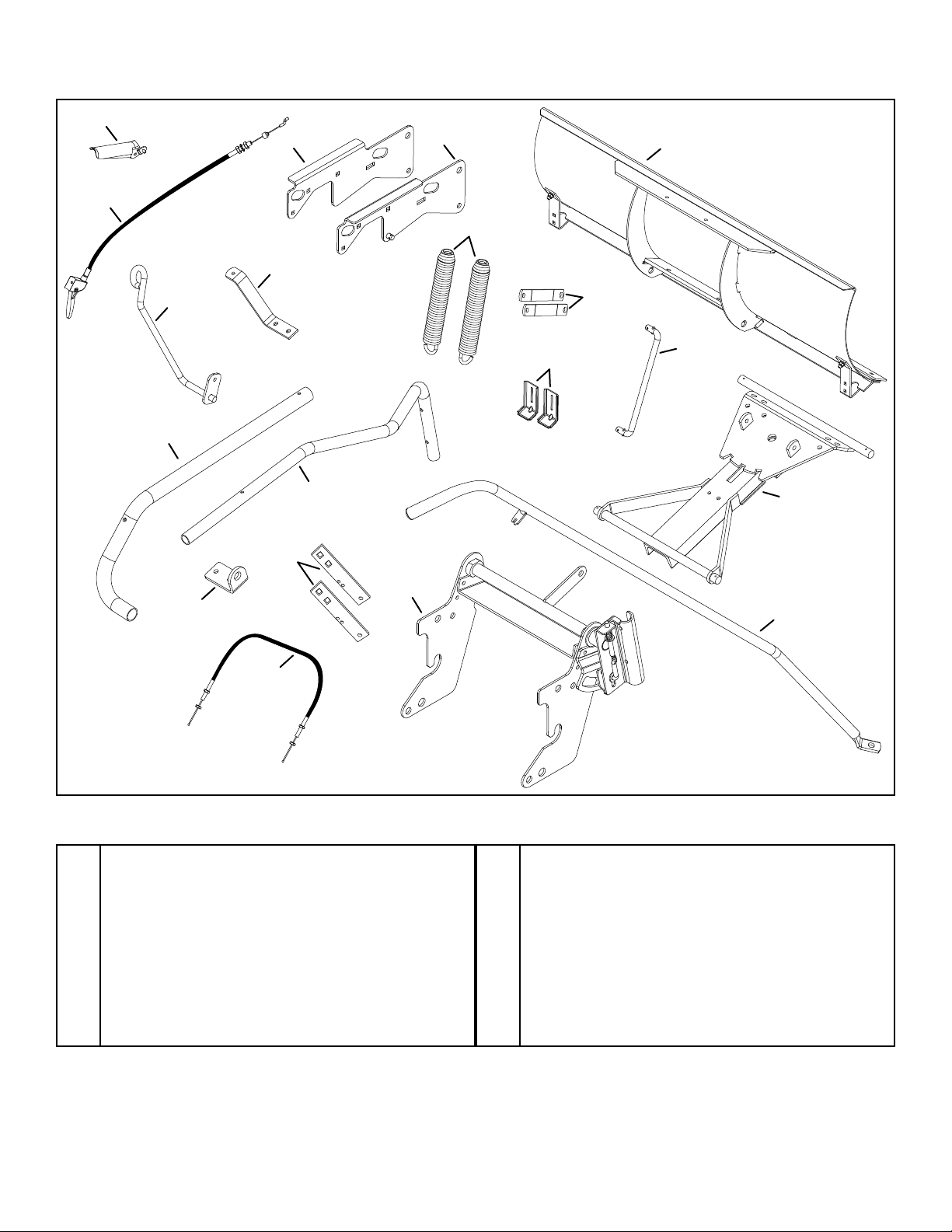
CONTENTS OF PARTS PACKAGE
REF PART NO. QTY. DESCRIPTION
A 43510 2 Hex Bolt, 1/2" x 2-3/4"
B 41596 2 Hex Bolt, 1/2" x 2"
C 43020 2 Hex Bolt, 1/2" x 1-1/2"
D 43084 2 Hex Bolt, 5/16" x 1-3/4"
E 43087 2 Hex Bolt, 3/8" x 1-1/4"
F 43001 4 Hex Bolt, 3/8" x 1"
G 43182 2 Hex Bolt, 5/16" x 3/4"
H 44071 2 Hex Bolt, 3/8" x 3-1/2"
I 48106 1 Shoulder Bolt
J 43350 6 Carriage Bolt, 3/8" x 1"
K 710-0305 2 Carriage Bolt, 3/8" x 1-1/4"
L 44326 6 Carriage Bolt, 5/16-18 x 1"
M 43085 1 Hex Bolt, 5/16" x 1-1/2"
N 43648 2 Hex Bolt, 1/4" x 1-1/2"
O 43010 4 Cotter Pin, 1/8" x 1-1/4"
P 712-3083 4 Nylock Nut, 1/2"
Q HA21362 10 Nylock Nut, 3/8"
R 47189 3 Nylock Nut, 1/4"
S 44072 1 Whizlock Hex Nut, 3/8"
T 712-0256 2 Hex Jam Nut, 5/16"
U 23658 1 Spacer, Long
REF PART NO. QTY. DESCRIPTION
V 47810 11 Nylock Hex Nut, 5/16"
W 712-0206 4 Hex Nut, 1/2"
X 43015 4 Hex Nut, 3/8"
Y 47364 2 Spacer, Short
Z 43003 4 Lock Washer, 3/8"
AA 49344 1 Screw, #10 x 1-3/4"
BB 43009 2 Washer, 3/4"
CC R19172410 8 Washer, Large
DD R19212113 6 Washer, 5/8"
EE R19171616 4 Washer, Small
FF 43081 4 Washer, 5/16"
GG 05762 1 Cable Mount Bracket
HH 726-0178 2 Nylon Tie
II 711-0309 4 Clevis Pin, 5/8"
JJ 44074 2 Plastic Cap
KK 43343 8 Hair Cotter Pin
LL 746-0260 2 Cable End Fitting
MM 43348 1 Extension Spring
NN 43349 1 Spring Pin,
OO 48083 1 Plastic Grip
ASSEMBLY
TOOLS REQUIRED FOR ASSEMBLY
(1) 7/16" Wrench
(1) 1/2" Wrench
(1) 9/16" Wrench
(1) 3/4" Wrench
(1) Adjustable Wrench
(1) Phillips Screwdriver
(1) Hammer
• Removeallpartsandhardwarepackagesfromthe
carton. Lay out parts and hardware and identify using
the illustrations on pages 3 and 4.
NOTE: Not all of the supplied parts and hardware will be
needed for one particular tractor. Unneeded items may be
discarded after assembly has been completed.
NOTE: Right hand (RH) and left hand (LH) are
determined from the operator's position while seated on
the tractor.
CAUTION: Do not begin assembling
until the tractor engine, muffler and exhaust
deector have been allowed to cool off.
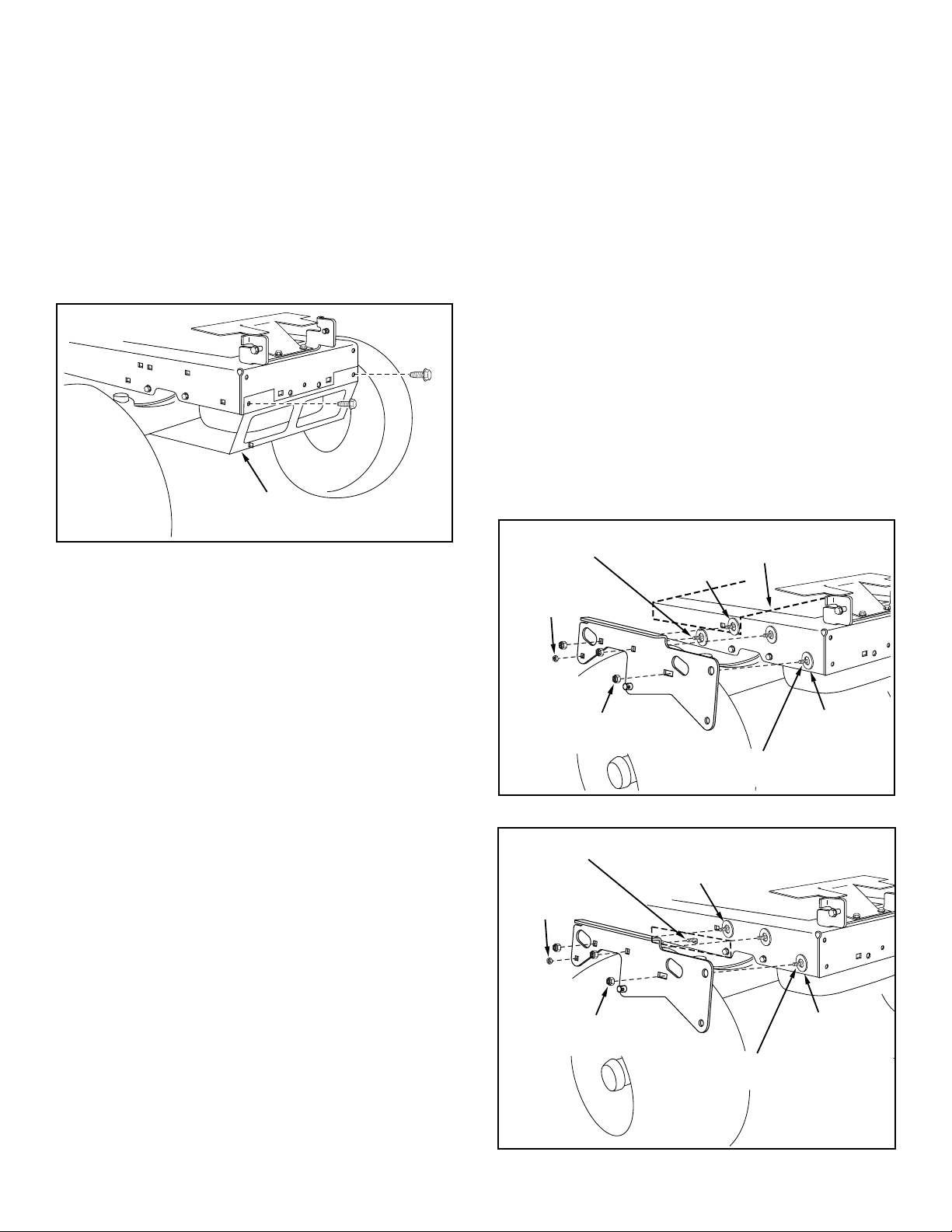
STEP 1: (SEE FIGURE 1)
• Lookunderthefrontofyourtractor.Ifthereisasingle
mower deck suspension bracket located underneath
the middle of the front axle, continue on to step 2. If
your tractor does not have a mower deck suspension
bracket underneath the middle of the front axle, skip
to step 5 on page 7 for tractors with dual suspension
brackets.
MOWER DECK
SUSPENSION
BRACKET
FIGURE 1

6
REMOVE
BROWNING SHIELD
FIGURE 2
FIGURE 3a
FIGURE 3b
5/16" NYLOCK
NUT (V)
3/8" NYLOCK
NUT (Q)
5/16" x 1" CARRIAGE
BOLT (L)
3/8" x 1" CARRIAGE
BOLT (J)
ENGINE MOUNTING
PLATE
LARGE 1/2"
WASHER (CC)
(SEE NOTE)
STEP 2: (SEE FIGURE 2)
• Remove the tractor hood. Refer to your tractor owners
manual for instructions on how to properly remove the
hood.
• Removethebrowningshieldfromthefrontofthe
tractor as shown. Hold onto the shield as you remove
the second bolt to prevent it from falling.
NOTE: Reinstall the browning shield before using your
tractor. Please see supplement page 20.
INSTRUCTIONS FORTRACTORS WITH SINGLE
FRONT DECK SUSPENSION BRACKET
STEP 3: (SEE FIGURE 3)
• If the third bolt goes through an engine mounting
plate (dotted lines) leave the 1/2" washer off that
bolt. Fasten the R.H. Side Plate (bend facing out) to
the front three holes in the tractor frame using three
3/8" x 1" carriage bolts (J), three large 1/2" washers
(CC) (see note) and three 3/8" nylock nuts (Q). For
the rear hole, use a 5/16" x 1" carriage bolt (L), a
large 1/2" washer (CC) and a 5/16" nylock nut (V).
Place the 1/2" washers (V) between the tractor frame
and the side plate. Tighten all bolts. Repeat for L.H.
side plate.
• If the tractor is a Husqvarna TS200 Series with
dual pedal there will be a bracket like the one
drawn with dotted lines in gure 3b. Fasten the
R.H. Side Plate (bend facing out) to the front three
holes in the tractor frame using three 3/8" x 1"
carriage bolts (J), three large 1/2" washers (CC) and
three 3/8" nylock nuts (Q). For the rear hole, use a
5/16" x 1" carriage bolt (L), and a 5/16" nylock nut (V).
Place the 1/2" washers (V) between the tractor frame
and the side plate. Tighten all bolts. Repeat for L.H.
side plate.
• Reinstall the browning shield removed in gure 2.
5/16" NYLOCK
NUT (V)
3/8" NYLOCK
NUT (Q)
5/16" x 1" CARRIAGE
BOLT (L)
3/8" x 1" CARRIAGE
BOLT (J)
LARGE 1/2"
WASHER (CC)
(SEE NOTE)

7
STEP 4: (SEE FIGURE 4)
• Placea1/2"washer(EE)andthenashortspacer(Y)
onto a 1/2" x 1-1/2" hex bolt (C). Install the bolt in the
bottom hole at the front of the R.H.side plate and secure
it with a 1/2" nylock nut (P). Repeat for the L.H. side
plate.
• Skip to step 8 on page 8.
FIGURE 4
1/2" WASHER (EE)
1/2" X 1-1/2"
HEX BOLT (C)
1/2" NYLOCK
NUT (P)
SPACER
SHORT (Y)
REMOVE BOLTS
FROM THESE HOLES
FRONT
SUSPENSION
BRACKET
REMOVE NUT & WASHER
AND LEAVE BOLT (IF PRESENT)
3/8" NYLOCK NUT (Q)
(IF NEEDED)
3/8" x 1"
HEX BOLT (F)
3/8" LOCK
WASHER (Z)
REMOVE NUT & WASHER
AND LEAVE BOLT (IF PRESENT)
1/2" WASHER (EE)
1/2" X 1-1/2"
HEX BOLT (C)
1/2" NYLOCK
NUT (P)
SPACER,
SHORT (Y)
STEP 5: (SEE FIGURE 5)
• Removeboltsfromholesshowninillustrationifthey
are present.
FIGURE 5
STEP 6: (SEE FIGURE 6)
• FastentheR.H.sideplate(bendfacingout)tothetwo
holes indicated in the tractor frame. Use two 3/8" x 1"
hex bolts (F) and 3/8" lock washers (Z). If the bolts insert
loosely into the tractor frame, use two 3/8" nylock nuts
(Q) on the inside of the frame. Repeat for the L.H. side.
FIGURE 6
FIGURE 7
STEP 7: (SEE FIGURE 7)
• Placea1/2"washer(EE)andthenashortspacer(Y)
onto a 1/2" x 1-1/2" hex bolt (C). Install the bolt in the
bottom hole at the front of the R.H.side plate and secure
it with a 1/2" nylock nut (P). Repeat for the L.H. side
plate.
• Go to step 8 on page 8.
INSTRUCTIONS FOR TRACTORS WITH DUAL
FRONT DECK SUSPENSION BRACKETS

8
STEP 8: (SEE FIGURE 8)
•Install a 1/2" x 2" hex bolt (B) and two 1/2" hex nuts
(W) in the outer hole in each side of the pivot plate.
Temporarily adjust the hex nuts so that both bolt
heads extend about an inch and a half above the
pivot plate.
STEP 10: (SEE FIGURE 10 and 11)
•Assemble the two angle lock bars together using a
3/8" x 1-1/4" carriage bolt (K) and a 3/8" nylock nut
(Q) in the top square holes. Do not tighten.
•Assemble the straight hook end of the extension
spring into the small holes in the angle lock bars.
Insert the lock bars down into the lock bar slot in
the channel pivot plate assembly.
STEP 9: (SEE FIGURE 9)
•Assemble the round hook end of the extension
spring into the hole in the washer as shown.
FIGURE 8
FIGURE 9
FIGURE 10
FIGURE 11
WASHER
EXTENSION
SPRING
CHANNEL/PIVOT
PLATE ASSEMBLY
MOUNT
ROD
CHANNEL/PIVOT
PLATE ASSEMBLY
3/8" X 1-1/4"
CARRIAGE BOLT
(TOP HOLE) (K)
EXTENSION
SPRING
ANGLE LOCK
BARS
FRONT
LOCK BAR
SLOT
SPRING PIN
HOLE
3/8" NYLOCK
NUT (Q)
• Aligntheanglelockbarswiththeweldedbracketon
the bottom of the channel. Use a hammer to drive
the 1/4" x 1" spring pin (NN) through the angle lock
bars and into the slot in the welded bracket.
• Tighten the nylock nut on the carriage bolt.
NOTE: The angle lock bars should pivot freely. When
they are pulled all the way back the pivot plate assembly
should be unlocked and free to pivot to the right or left
notches.
FRONT
POSITION
NOTCH
1/4" X 1"
SPRING PIN (NN)
LOCK
BARS
ANGLE
LOCK BARS
1/2" X 2" BOLT (B)
1/2" HEX NUTS (W)
INSTRUCTIONS FOR ALL TRACTORS

9
STEP 12: (SEE FIGURE 13)
•Select the control cable with two threaded ends.
Select the threaded end that has no rubber cap
or nuts and assemble a 5/16" hex jam nut (T)
approximately 3/4" onto the threads. Insert the
threaded end of the cable through the round hole
in the cable mount bracket (GG) and secure it with
another 5/16" hex jam nut (T). Tighten the second nut
while keeping the rst nut in place.
•Assemble the ball end of the cable wire up through
the hole in a cable end tting (LL) and then slide it
back inside the curled edge of the tting.
STEP 13: (SEE FIGURE 14)
•Attach the cable end tting (LL) and the long spacer
(U) to the left hand hole in the channel and lift bracket
using a 1/4" x 1-1/2" hex bolt (N) and 1/4" nylock nut
(R). Tighten, keeping the cable end tting aligned
with the threaded end of the cable.
FIGURE 12
FIGURE 14
STEP 14: (SEE FIGURE 15)
•Attach the lift bracket to the right hand hole in the
channel, next to the long spacer. Use a 5/16" x 3/4"
hex bolt (G) and 5/16" nylock nut (V).
•Attach the frame assembly to the channel assembly.
Fit one side of the frame assembly onto the 3/4" rod
of the channel and then t the other side onto the rod.
Secure each side with a 3/4" washer (BB) and a 1/8"
x 1-1/4" cotter pin (O).
STEP 11: (SEE FIGURE 12)
•Assemble a 3/8" x 1-1/4" carriage bolt (K) through
the cable mount bracket (GG) and then mount it
from the left side to the square holes in the angle
lock bars. Secure the bracket at the angle shown in
gure 14 with a 3/8" nylock nut (Q).
CABLE MOUNT
BRACKET (GG)
ANGLE
LOCK
BARS
3/8" X 1-1/4"
CARRIAGE BOLT (K)
3/8" NYLOCK NUT (Q)
CHANNEL
LIFT BRACKET
LONG SPACER (U)
1/4" X 1-1/2"
HEX BOLT (N)
1/4" NYLOCK NUT (R)
CABLE END
FITTING (ll)
CABLE MOUNT BRACKET
FIGURE 13
CONTROL CABLE END
CABLE
MOUNT
BRACKET (GG) 3/4"
5/16" HEX
JAM NUTS (T)
CABLE END
FITTING (LL)
BALL END
CABLE
FIGURE 15
LIFT BRACKET
3/4" ROD
3/4" WASHER (BB)
1/8" x 1-1/4"
COTTER PIN (O)
5/16" X 3/4" BOLT (G)
5/16" NYLOCK
NUT (V)
FRAME ASSEMBLY

10
FIGURE 16
STEP 15: (SEE FIGURE 16)
• Attachtheendsoftheliftrodtotheliftbracketonthe
channel and the welded arm on the frame assembly.
Use two small 1/2" washers (EE) and 1/8" x 1-1/4"
cotter pins (O).
5/16" x 1" CARRIAGE
BOLT (L)
5/16" WASHER (FF)
5/16" NYLOCK
NUT (V)
FIGURE 18
STEP 17: (SEE FIGURE 18)
• Attachtheskidshoestothebladeusingfour5/16"x
1" carriage bolts (L), 5/16" at washers (FF) and 5/16"
nylock nuts (V). Do not tighten yet.
FIGURE 17
3/8" NYLOCK
NUT (Q)
BLADE PIVOT
BRACKET
PIVOT PLATE
ASSEMBLY
5/16" X 3/4"
BOLT (G)
5/16" NYLOCK
NUT (V)
HANDLE GUIDE
3/8" x 1-1/4"
BOLT (E)
STEP 16: (SEE FIGURE 17)
• Assemblethebladepivotbrackettothepivotplate
assembly using two 3/8" x 1-1/4" bolts (E) and 3/8"
nylock nuts (Q).
• Assemblethehandleguidetotheframeassembly
using a 5/16" x 3/4" bolt (G) and 5/16" nylock nut (V).
BLADE MOUNT
GUSSET
HAIR COTTER
PIN (KK)
STEP 18: (SEE FIGURE 19)
• Alignthechannelpivotplateassemblybehindthe
blade and guide the ends of the mounting rod, one
end at a time, into the holes at the bottom of the
blade mount gussets. Secure the mounting rod with
two hair cotter pins (KK).
FIGURE 19
COTTER
PIN (O)
LIFT ROD
1/2" WASHER,
SMALL (EE)
WELDED ARM

11
3/4"
CONTROL CABLE END
HANDLE
ASS'Y. HANDLE
GUIDE
JAM NUTS
RUBBER CAP
STEP 22: (SEE FIGURE 23)
• Removetherubbercapandtherstjamnutfrom
the threaded end of the control cable and slide them
onto the control cable wire. Adjust the second jam nut
on the threads so that it is approximately 3/4" from
end. Assemble threaded end of cable through the
cable mount ear and secure it with the rst jam nut.
Reinstall the rubber cap onto the threaded cable end.
FIGURE 23
SPRING ASSEMBLY
3/8" HEX NUT (X)
PLASTIC CAP (JJ)
SPRING
MOUNT EAR
STOP BOLT
1-1/2"
1"
STEP 20: (SEE FIGURE 21)
• Hookthespringassembliesintothespringmount
ears on the pivot plate. Insert the end of each bolt
up through the holes in the top of the blade and
assemble a 3/8" hex nut (X) onto each trip spring.
Tighten both nuts on each bolt so that approximately
1" of the bolt extends through the top of the blade.
• Assembletheplasticcaps(JJ)ontothebolts.
• Adjustthestopboltsinthepivotplatesothatthebolts
extend equally 1-1/2" above the pivot plate, creating
tension on the spring assemblies.
FIGURE 21
SHOULDER
BOLT (I)
3/8" HEX
WHIZLOCK
NUT (S) BLADE
PIVOT
BRACKET
HANDLE
TUBE
PLASTIC
TIE (HH)
CONTROL
CABLE
FIGURE 22
STEP 21: (SEE FIGURE 22)
• Slidethehandleassemblythroughthehandleguide
so that the attened end rests on the blade pivot
bracket.
• Securetheendofthehandletothetopsideofthe
blade pivot bracket with the shoulder bolt (I) on top
and a 3/8" hex whizlock nut (S) underneath.
• Securecabletohandletubewithaplastictie(HH)
near bottom of handle. Cut off extra plastic on end.
3/8" X 3-1/2"
HEX BOLT (H) BLADE TRIP SPRING
3/8" HEX NUT (X)
FIGURE 20
STEP 19: (SEE FIGURE 20)
• Inserteach3/8"x3-1/2"hexbolt(H)intoabladetrip
spring.
• Assemblea3/8"hexnut(X)ontotheendofeach3/8"
x 3-1/2" hex bolt (H) leaving the nut about 2" from the
end of the bolt.

12
1/4" x 1-1/2"
BOLT (N)
1/4" NYLOCK
NUT (R)
FIGURE 25
STEP 24: (SEE FIGURE 25)
• Assembletheupperlifthandleontothelowerlift
handle and fasten using a 1/4" x 1-1/2" bolt (N) and
1/4" nylock nut (R). #10
SCREW (AA) LIFT RELEASE
CABLE
HEX NUT
JAM NUT
LOCK
WASHER
CABLE
WIRE
INDEX
LIFT
ROD
TRIGGER
ASSEMBLY
LIFT HANDLE
LIFT BRACKET
5/16" X 1-3/4"
HEX BOLT (D)
5/16" NYLOCK
NUT (V)
FIGURE 26
STEP 25: (SEE FIGURE 26)
•Attach the lower lift handle to the right side of the
frame assembly using two 5/16" x 1-3/4" hex bolts (D)
and 5/16" nylock nuts (V).
FIGURE 27
STEP 26: (SEE FIGURE 27)
• Installthetriggerassemblytothelifthandleusingan
oval screw (AA).
• Connectthehookedendofthecablewireintothe
index lift rod. Install the threaded end of the cable into
the notch in the top of the lift bracket, placing one jam
nut on each side of the notch with the lock washer
below the notch.
• Adjustthejamnutssothatwhenthetriggeronthe
lift handle is squeezed, the bottom of the index lift rod
raises enough to release from the latched position.
The index lift rod should also lower far enough to lock
in the latched position when the trigger is released.
• Securecabletohandlewithaplastictie(HH)to
prevent cable from interfering with tractor. Cut off
extra plastic on end of tie.
GRIP ASSEMBLY
HANDLE
ASSEMBLY
5/16" X 1-1/2"
HEX BOLT (M)
CABLE END
FITTING (LL)
1/4" WELD BOLT
5/16" NYLOCK
NUT (V)
CABLE
1/4" NYLOCK
NUT (R)
GRIP (OO)
FIGURE 24
STEP 23: (SEE FIGURE 24)
• Assemblegrip(OO)togripassembly.
• Assemblegripassemblytohandleassemblyusinga
5/16" x 1-1/2" hex bolt (M) and 5/16" nylock nut (V).
• Assembletheballendofthecablewire(shownin
gure 23) up through the hole in a cable end tting
(LL) and then slide it back inside the curled edge of
the tting.
• Assemblecableendtting(LL)over1/4"weldbolton
grip assembly and secure with one 1/4" nylock nut (R)
and then back nut off 1/2 turn.
NOTE: Do not over tighten 1/4" nylock nut, cable end
tting must pivot freely.

13
MOUNTING BLADE TO TRACTOR
STEP 1: (SEE FIGURE 28)
• Attachtheframeassemblytotheframebracketsby
sliding the notches in the frame assembly onto the
bolts on the frame brackets.
ATTACH FRAME ASSEMBLY
TO BOLTS SHOWN
FIGURE 28
LIFT LINK
HAIRCOTTER
PIN (KK)
FIGURE 30
CLEVIS
PIN (II)
HAIRCOTTER
PIN (KK)
LIFT LINK
CLEVIS
PIN (II) FRAME ASSEMBLY
5/8" WASHERS (DD)
FIGURE 31
FIGURE 29
STEP 4: (SEE FIGURE 31)
• Attachtheliftlinkstotheframeassembly:
A. Insert a 5/8" clevis pin (II) through the frame
assembly from the outside.
B. Place two 5/8" washers (DD) onto the clevis pin.
C. Place the end of the lift link onto the clevis pin.
D. Place a 5/8" washer (DD) onto the clevis pin
and secure with a hair cotter pin (KK).
STEP 3: (SEE FIGURE 30)
• Attachthesmallholesoftheliftlinkstothewelded
pins on the frame bracket and secure with hair cotter
pins (KK). The lift link should angle to the inside.
STEP 2: (SEE FIGURE 29)
• Standontherightsideoftheblade.Squeezethe
trigger on the lift handle and lift the handle. Release
the trigger, but do not allow handle to lower into
locked position.
• Standontheleftsideoftheblade.Griptheroundbar
at the top of the frame assembly and lift up to align
the holes in the frame assembly with the holes in the
frame brackets.
• Inserttwo5/8"clevispins(II)throughtheholesinthe
frame assembly and the frame brackets and secure
with two hair cotter pins (KK).
NOTE: Blade hidden in illustration for better view.
LIFT
HANDLE
CLEVIS PIN,
5/8" (II)
HAIRCOTTER
PIN (KK)
ROUND BAR

14
OPERATION
WARNING: Hidden objects can cause
sudden stops or change in direction
CONTROLS
Become familiar with all of the controls and adjustments
on the tractor and dozer blade before operating. Refer to
tractor owners manual for tractor controls. Controls for
operatingdozerbladeareasfollows:
LIFT HANDLE: (Figure 32)
Located on right hand side of tractor. To raise the
dozer blade, push the lift handle down until blade
locks in the up position. To lower the dozer blade,
push down slightly on the lift handle, depress trigger
and then lift up on handle to lower the blade.
BLADE ANGLE HANDLE: (Figure 32)
Located on the left hand side of tractor. When dozer
blade is in the up position, depress grip assembly
and push or pull on handle to swivel blade to the right
or left. Release grip assembly to lock the blade in the
left, center or right position.
NOTE: Always raise dozer blade and lock in up position
before moving blade angle handle.
CAUTION: Know the terrain. Avoid
exceptionally sharp slopes or drop-offs
which may be hidden by the snow.
WARNING: Never run the dozer blade
into heavy material at high speed.
LIFT HANDLE
BLADE ANGLE
HANDLE
LIFT HANDLE
TRIGGER
GRIP ASSEMBLY
FIGURE 32
• Preparethetractorengineforcoldweatherby
following the instructions furnished with the tractor.
• Inspecttheareatobeworkedcarefullybefore
operating the dozer blade. Avoid pipes, roots, curbs or
other heavy obstructions.
• Alwaysbegintransmissioninrst(low)gearand
gradually increase speed as required.
• Operate tractor at reduced speed when dozer blade
trip springs are locked out. Refer to Service and
Adjustment section.
• Ifbladeisstoredinheatedarea,allowtractorblade
to adjust to outdoor temperature before operating to
reduce icing on the metal surfaces.
• Forimprovedshowremovalperformance,coatthe
blade with automotive type paste wax.
CAUTION: Always lower blade to
ground before leaving tractor
NOTE: Wheel weights and tire chains should be used
with your dozer to improve traction. For additional traction,
install wheel weight on rear of draw bar using a weight
bracket kit and one wheel weight from a wheel weight kit.
These accessories are available at your nearest Sears
retail or catalog sales.
USING THE DOZER BLADE

15
DOZER SPRING LOCKOUT: (Figure 34)
To lock dozer blade spring trip action for heavy dozer
work, install two 1/2" x 2-3/4" hex bolts (A) (included
in hardware package.) Secure with two 1/2" nylock
nuts (P).
BLADE SHOE ADJUSTMENT: (Figure 35)
Blade shoes on end of blade may be raised for clean
dozing on smooth surfaces or lowered to raise the
blade to work on rough or uneven areas. Make sure
both shoes are set evenly and nuts are tightened
securely
(P)
(A)
FIGURE 34
BLADE
SHOE
BLADE
FIGURE 35
BLADE ANGLE LOCK BARS: (Figure 33)
If angle lock bars DO NOT completely disengage from
slots in pivot plate assembly, adjustment of cable is
required.
ADJUST BLADE SPRINGS: (Figure 33)
To change spring tension, stand in front of blade
assembly and adjust the nuts at the upper end of the
springs. Turn counter clockwise to decrease tension
and clockwise to increase tension.
Adjust spring adjustment nuts approximately 1"
from end when moving snow or other light material.
Keep spring tension light for safety. This frees the
blade to spring trip and return if a hidden obstacle is
encountered.
SPRING ADJUSTMENT
NUTS (OUTSIDE)
SPRING ADJUSTMENT
NUTS (INSIDE)
BLADE
ASSEMBLY
PIVOT PLATE
ASSEMBLY CABLE
LOCK
BARS
SPRING
ADJUSTMENT
BOLTS
FIGURE 33
SERVICE AND ADJUSTMENTS

16
SCRAPER
BAR
BLADE
ASSEMBLY
CARRIAGE BOLTS
AND NUTS
FIGURE 36
CHECK FOR LOOSE FASTENERS
• Duringtheoperatingseason,checkallbolts,nutsand
hairpin cotters to be sure they are secure.
CHECK SCRAPER AND SHOES FOR WEAR
• Duringtheoperatingseason,checkthescraperand
shoes for wear before each use. After extensive use
and wear, the scraper bar may be reversed to utilize
the unused top edge. See gure 36.
CLEAN BLADE
• During the operating season, clean the blade off after
each use. Touch up any bare metal with paint or
apply a light coat of grease or rust preventive.
LUBRICATE BLADE
• Oilallpivotpointseachseasonsotheywillwork
freely.
CUSTOMER RESPONSIBILITIES
• Readandfollowthemaintenancescheduleandthemaintenanceprocedureslistedinthissection.
Service Dates
Check for loose fasteners X
Check scraper and shoes for wear X
Clean Blade X X
Lubricate Blade X
MAINTENANCE SCHEDULE
Fill in dates as you
complete regular service.
Before each use
After each use
Every season
Before storage
MAINTENANCE
TROUBLESHOOTING
PROBLEM CAUSE CORRECTION
Blade is difficult to raise. Lift mechanism is binding. Lubricate pivot points.
Blade is difficult to pivot. Handle tube is binding on lift rod. Lubricate lift handle rod.
Blade will not unlock to pivot. Lock mechanism is out of adjustment
and is not disengaging.
Refer to the Operation section on page 14.

17
RECOMMENDATIONS WHEN STORING
• Whenthedozerisnotbeingused,removealldirtand
rust and touch up with paint.
• Applyalightcoatofgreaseorrustpreventiontothe
blade and oil pivot points.
• Storeinanareawhereitisprotectedfromweather.
• Storeinadryarea,protectedfromweather.
REMOVING DOZER BLADE FROM TRACTOR
1. Lower blade to ground with blade in the center
(straight ahead) position.
2. Refertogure37below:
A. Remove cotter pins and lift links from side plates.
B. Remove clevis pins from blade frame
assembly.
C. Pull blade frame assembly from side plates.
NOTE: Frame brackets do not require removal unless a
different attachment is mounted to front of tractor.
FIGURE 37
STORAGE
CLEVIS PIN
LIFT LINK
HAIRPIN
COTTER

18
46
1
2
3
3
5
5
5
5
4
6
7
7
8
9
76
76
5
3
5
10
41
40
63
51
67
67
51
65
64
81
62
24
34
59
59
26
25
22
38
3736
37
36
16
60
50
17
18
61
19 86
5
21 A
45
50
13
73 20
44
44
15
28
27
74
5
5
30
29
31
33
32
31
31
74
11
68
50
5
79
11
12
14
58
53
47
64
54
54
46
46
46
55
42
65
65
78
78
78
49
49
49
57
39
75
75
76
71 85
82
83
84
77
46
55
56
23
80 35
23
45
60
66
48
52
52 A
69
70
49
43
48
49
72
3
55
REPAIR PARTS FOR MODEL 45-04552 - 48" DOZER BLADE

19
REPAIR PARTS FOR MODEL 45-04552 - 48" DOZER BLADE
REF PART NO. QTY. DESCRIPTION
1 65380ORG 1 48" Blade Assembly
2 25701 2 Skid Shoe Bracket
3 44326 12 Carriage Bolt, 5/16-18 x 1"
4 43682 2 Carriage Bolt, 5/16-18 x 1-1/4"
5 47810 19 Nylock Hex Nut, 5/16"
6 23639GY 1 Wear Plate 48"
7 R3132J 2 Skid Shoe
8 62556 1 Pivot Plate Assembly
9 65358 1 Channel Assembly
10 710-0741 1 Hex Bolt 3/4-10 x 3-1/2"
11 1540-162 1 Washer 3/4"
12 40436 1 Hex Jam Nut, 3/4-10
13 7071 1 Handle Grip
14 40598 1 Hex Lock Nut, 3/4-10
15 49264GY 1 Lift Handle Tube (Lower)
16 49265GY 1 Lift Handle Tube (Upper)
17 47674 1 Tube Plug
18 49912 1 Trigger & Lift Cable Assembly
19 48083 1 Plastic Grip
20 65348GY 1 Handle Assembly
21 49808 1 Control Cable
22 65359 1 Lift Assembly
23 24312 2 Mounting Bracket
24 741-0192 2 Flange Bearing (w/ Flats)
25 43093 1 Cotter Pin, 1/8 x 1-1/2"
26 43601 1 Washer, 1.59" x 1.032" x 0.60"
27 47368 1 Spring Pin, 5/16" x 1-3/4"
28 23151 2 Angle Lock Bar (Short)
29 67784GY 1 Bracket Handle Lift Assembly
30 732-0306 1 Compression Spring
31 R19131316 3 Washer, 3/8" x 13/16" x 1/16"
32 142 1 Cotter Pin, 1/8" x 3/4"
33 48049 1 Index Lift Rod
34 43063 2 Hex Bolt, 5/16" x 1"
35 43840 2 Hex Bolt, 5/16" x 1-1/4"
36 43064 4 Hex Lock Nut, 5/16"
37 43086 4 Lock Washer, 5/16"
38 25666 1 Spacer Bracket
39 65436GY 1 Tube Guide Bracket Ass'y.
40 65403 1 Side Plate (Left Hand)
41 65402 1 Side Plate (Right Hand)
42 49819 1 Lift Rod
43 23646 1 Blade Pivot Bracket
44 726-0178 2 Nylon Tie
45 746-0260 2 Cable End Fitting
REF PART NO. QTY. DESCRIPTION
46 43343 8 Haircotter Pin, 3/32" x 2-5/16"
47 43510 2 Hex Bolt, 1/2" x 2-3/4"
48 710-0305 2 Carriage Bolt, 3/8" x 1-1/4"
49 HA21362 10 Nylock Hex Nut, 3/8"
50 47189 3 Nylock Hex Nut, 1/4"
51 43001 4 Hex Bolt, 3/8" x 1"
52 712-0256 2 Hex Jam Nut, 5/16"
53 41596 2 Hex Bolt, 1/2" x 2"
54 712-0206 4 Hex Nut, 1/2"
55 711-0309 4 Clevis Pin, 5/8" x 1.2"
56 R19212113 6 Washer, 5/8" SAE
57 R19172410 8 Washer, 1/2" x 1-1/2"
58 43087 2 Hex Bolt, 3/8" x 1-1/4"
59 43081 6 Washer, 5/16"
60 43648 2 Hex Bolt, 1/4" x 1-1/2"
61 49334 1 Screw, #10 x 1-3/4"
62 47364 2 Spacer, .52" x .75" x .4"
63 43020 2 Hex Bolt, 1/2" x 1-1/2"
64 712-3083 4 Nylock Nut, 1/2"
65 R19171616 4 Washer, 1/2" x 1" (Small)
66 25688 1 Lift Rod Bracket
67 43003 4 Lock Washer, 3/8"
68 43349 1 Spring Pin, 1/4" x 1"
69 05762 1 Cable Mount Bracket
70 43348 1 Extension Spring
71 48106 1 Shoulder Bolt
72 23658 1 Spacer, .39" x .56" x .62"
73 43085 1 Hex Bolt, 5/16" x 1-1/2"
74 43084 2 Hex Bolt, 5/16" x 1-3/4"
75 43182 2 Hex Bolt, 5/16" x 3/4"
76 43010 4 Cotter Pin, 1/8" x 1-1/4"
77 44072 1 Whizlock Hex Nut, 3/8"
78 43350 6 Carriage Bolt, 3/8" x 1"
79 43009 2 Washer, 3/4"
80 24298 1 Lift Bracket
81 25725 2 Lift Link
82 R9466R 2 Trip Spring
83 44071 2 Hex Bolt, 3/8" x 3-1/2"
84 43015 4 Hex Nut, 3/8"
85 44074 2 Plastic Cap
86 62561 1 Release Grip Assembly
40412 1 Owners Manual

20
SUPPLEMENT SHEET
SUBJECT:
INTERFERENCE WITH BROWNING SHIELD AND LOWER DASH COVER
FORM NO. 42799 (05/06/13)
If your Husqvarna tractor is equipped with the browning shield shown below, it will be necessary to
remove it in order to mount this attachment. (Does not apply for front mount scoops). It is critical that
you reinstall the browning shield when the attachment is removed.
BROWNING SHIELD
LOWER DASH
COVER
If your Husqvarna TS200 Series tractor is equipped with lower dash covers as shown below, it will be necessary to
remove them in order to mount this attachment. (Does not apply for front mount dethatchers). Refer to
your tractor manual for removal instructions.
CAUTION!
down before removing browning
shield.
Table of contents