349639_0306
7
Rear catcher pickup and collection
Follow normal tractor and mower deck start-up and
operating procedures as outlined in the tractor owner’s
manual. The rear catcher will operate when the mower deck
clutch switch is engaged. To stop the rear catcher, return the
deck clutch switch to the disengaged position.
Proceed to mow in the normal manner and occasionally
glance at the bags. When the bags are filled, move the deck
clutch switch to the disengaged position. Then drive the
machine to the unloading area.
It is best that the bags be unloaded before the discharge
chute and tube areas become clogged. If clogging occurs, it
will be necessary to clean the discharge chute and tube areas
of all material before starting to mow again.
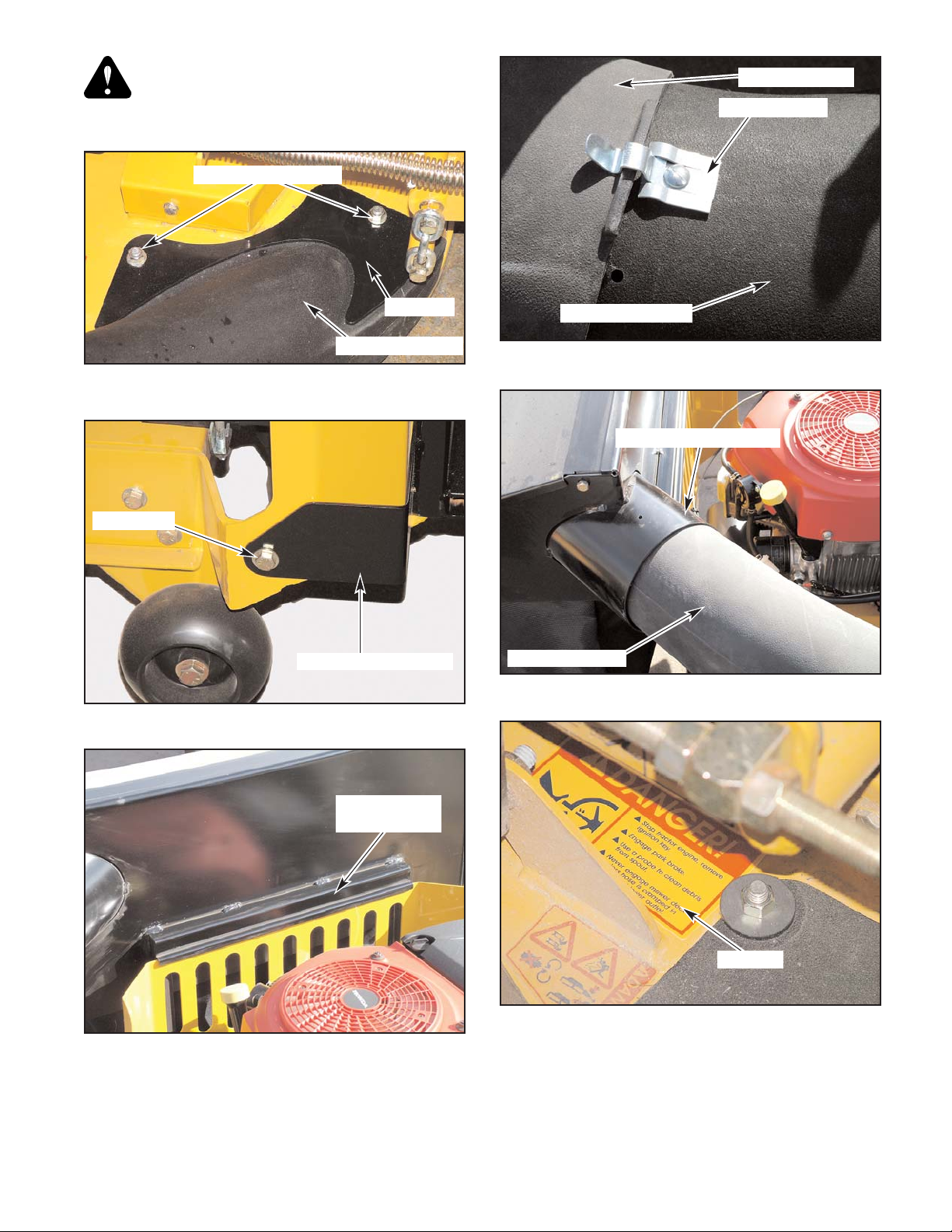
WARNING: Make certain the engine is turned
off and the ignition key is removed from the
ignition switch before cleaning the discharge
chute and flexible transfer tube areas.
WARNING: Never place hands or feet into the
discharge chute area. The mower blade is
relatively close to the discharge chute and
housing and will cause severe injury. Use a
probe to clean debris from discharge chute
area.
WARNING: Never engage mower deck unless
hose is clamped in place on discharge chute and
rear catcher lid intake tube. Fig. 15
When the bags are full, turn the deck off (deck clutch
switch in the disengaged position). Then drive the machine
to the unloading area.
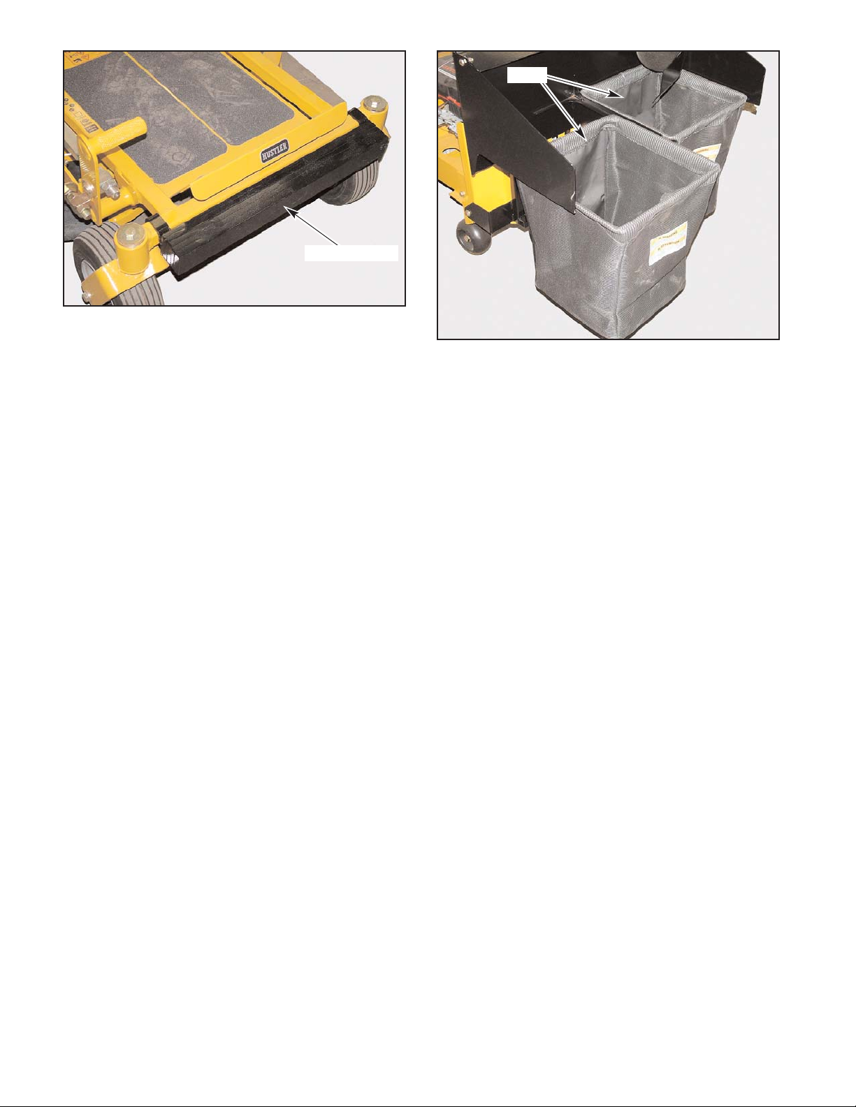
Unloading
WARNING: Make certain the deck clutch
switch is in the disengaged position before
unloading.
To dump the bags, park the tractor on a flat surface and
place the steering control levers in the park brake position.
Shut off the ignition switch and remove the key from the
switch. Get off the seat, raise the bagger lid and remove the
bags.
IMPORTANT: When re-installing the bags into the
catcher frame make sure the solid fabric side of the bag is
towards the front of the machine. This reduces the clipping
buildup in the engine compartment. The other three sides of
the bag is a mesh material which allows for better air flow.
Maintenance
WARNING: Never work on the mower deck
when the tractor engine is running.
To clean the flexible transfer tube and discharge chute
areas use the following procedure:
1. Turn the engine off and remove the key from the
ignition switch.
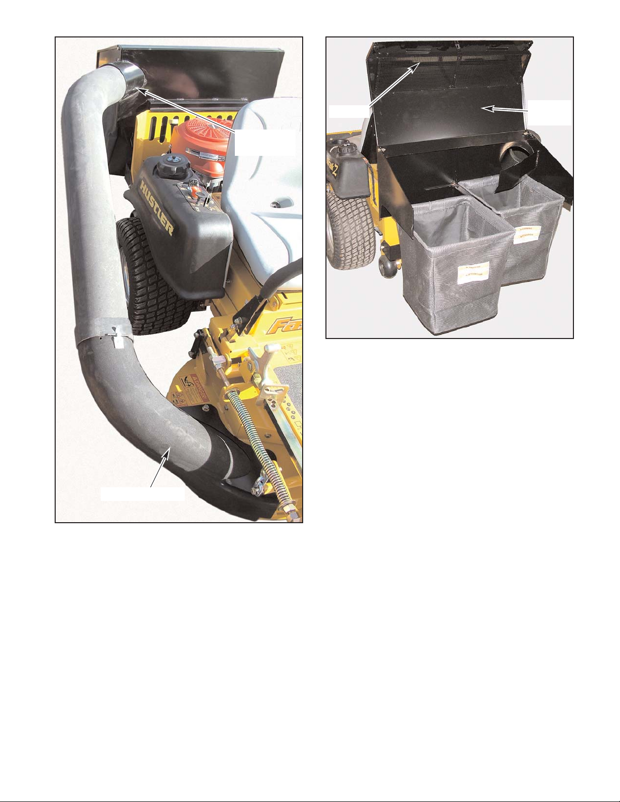
2. Remove the flexible transfer tube from the discharge
chute and rear catcher lid intake tube. Fig. 11
The flexible transfer tube can be cleaned by using soapy
water and rinse with water.
NOTE: It will be necessary to use a power washer of
some type to remove all of the debris from the inside of the
rear catcher lid and the discharge chute areas.
The screen located inside the rear catcher lid is accessible
when the lid is in the raised position. For maximum
performance, these screens must be kept clean by brushing
or washing as required. Fig. 16
WARNING: Clean flammable materials from
the machine. Prevent fires by keeping the engine
compartment and operator station clean of
accumulated trash, grass clippings, and other
debris.