Spearhead MULTICUT 820 User manual

Spearhead MULTICUT 820
1
MULTICUT 820
7th Edition –October 2013
Part No. 8999026

Spearhead MULTICUT 820
2
Spearhead
MULTICUT 820
Handbook
7th Edition –October 2013
Important Note
The information contained in this manual is correct at the time of publication.
However, in the course of constant development, changes in specification are
Inevitable. Should you find the information given in this book different to the
Machine it relates to please contact the “After Sales Department” for advice.
© Spearhead Machinery Limited 2004
Please ensure that this manual is handed to the operator before using the
machine for the first time. The operator must fully understand the contents
of this manual before using this machine.
(If the machine is resold the Manual must be given to the new owner.)
Spearhead Machinery
Green View
Salford Priors
Evesham
Worcestershire
WR11 8SW
Tel: 01789 491860
Fax: 01789 778683
www.spearheadmachinery.com
enquiries@spearheadmachinery.com

Spearhead MULTICUT 820
3
CE Declaration of Conformity,
Conforming to EU Machinery Directive
2006/42/EC
We, Spearhead Machinery Ltd, Green View, Salford Priors,
Evesham, Worcestershire, WR11 8SW hereby declare that:
Product
……………………………………………..…………………………
Product Code
……………………………………………..…………………………
Serial No
……………………………………………..……..………………….
Type
……………………………………………..…………………………
Manufactured by: Alamo Manufacturing Services (UK) Limited, Station
Road, Salford Priors, Evesham, Worcestershire, WR11 8SW
Complies with the required provisions of the Machinery Directive
2006/42/EC. The Machinery Directive is supported by the following
harmonized standards:
BS EN ISO 14121-1 (2007) Safety of Machinery –Risk Assessment,
Part 1: Principles Part 2: Practical Guide and Examples of Methods.
BS EN ISO 12100-1 (2010) Safety of Machinery –Part 1: Basic
Terminology and Methodology Part 2: Technical Principles.
BS EN 349 (1993) + A1 (2008) Safety of Machinery –Minimum
Distances to avoid the Entrapment of Human Body Parts.
BS EN 953 (1998) Safety of Machinery –Guards General
Requirements for the Design and Construction of Fixed and Movable
Guards.
BS EN 982 (1996) + A1 (2008) Safety Requirements for Fluid Power
Systems and their Components. Hydraulics.
The EC Declaration only applies if the machine stated above is used in
accordance with the operating instructions.
Signed
(On behalf of Spearhead Machinery Ltd)
Status
General Manager
Date
………………………………………………

Spearhead MULTICUT 820
4
Contents
Contents 4
Safety 5
Introduction 8
Tractor Requirements 8
Attaching To The Tractor 8
Setting Up Your Machine 9
Operation 12
Transportation 13
Machine Protection 14
Servicing & Maintenance
Safety First 15
Daily 16
Every 8 Hours 17
Torque Settings 17
Regularly 18
Blades 18
Slip Clutch Settings 19
Skids 23
Storage 23
Trouble Shooting Guide 24

Spearhead MULTICUT 820
5
Safety Recommendations
Beware of the following Potential Dangers associated with the use of
this machine:
Becoming trapped when hitching or unhitching
Machine overbalancing when wing is raised.
Getting caught on rotating power take off (PTO)
Being hit or caught by any moving part, e.g. Blades, drive shaft and wings.
Being hit by flying debris or machine parts due to machine damage
Machine overbalancing when not in use
Injection of high pressure oil from damaged couplings or hydraulic hoses
Accidents due to collision with other machines, or debris left on road
Beware of free-swinging blades over centering and falling when wings are
folding.
ALWAYS:
Ensure the operator has read this handbook and has been trained to use the
machine.
Ensure all safety guards are in place and all tractor windows closed.
Impact resistant shielding to the tractor is recommended
Before leaving the tractor cab always ensures that the wings are firmly on the
ground, no weight is on the machine’s hydraulics and the rotor has stopped
spinning.
Check that all guards are properly fitted and there are no damaged or loose
parts. Particular attention should be given to the blades to ensure they are not
damaged, cracked or missing
Inspect work area for wire, steel posts, large stones and other dangerous
materials and remove before starting work.
Ensure that all warning labels are always visible and that they are not
damaged, defaced or missing.
Fit locking pins to height and strap to wings before transport and before
unhitching when applicable.
Wear ear defenders if operating without a quiet cab or with the cab windows
open
Ensure tractor guards are fitted correctly and are undamaged
Work at a safe speed, taking into account terrain, passing vehicles and
obstacles

Spearhead MULTICUT 820
6
Ensure that the tractor meets the minimum weight recommendations of the
machine manufacturer and that ballast is used if necessary
Check that machine fittings and couplings are in good condition
Follow the manufacturer’s instructions for attachment and removal of machine
from the tractor
Ensure blades are of the type recommended by the manufacturer, are
securely fitted and are undamaged
Ensure hydraulic pipes are correctly routed to avoid damage from chafing,
stretching, pinching or kinking.
Check condition of tyres and tightness of wheel nuts.
Ensure all blades have stopped spinning before folding wings into transport
position.
Disengage the machine, stop the engine and remove the key before leaving
the tractor cab for any reason
Clean up any debris left at the work site.
Ensure that when you remove the machine from the tractor it is secured in a
safe position using the stands provided.
NEVER:
Never operate the machine with other people present, as it is possible for
debris, including stones, to be discharged from the front and rear.
Never operate the machine until you have read and understood this
Handbook and are familiar with the controls.
Never use a machine that is poorly maintained or has guards that are
damaged or missing
Never allow an inexperienced person to operate the machine without
supervision.
Never use or fit a machine onto a tractor if it doesn’t meet the manufacturer’s
specification.
Never use a machine if the hydraulic system shows signs of damage.
Never attempt to detect a hydraulic leak with your hand, use a piece of card.
Never allow children to play on or around the machine at any time.
Never attempt any maintenance or adjustment without first disengaging the
PTO, lowering the wings to the ground, stopping the tractor engine and
applying the tractor parking brake.
Never leave the cab without removing the ignition key.
Never operate the tractor or any controls from any position other than from
the driving seat.
Never stop the engine with the PTO engaged.
Never operate with blades missing.
Never operate PTO above recommended speed, 1000 r.p.m.
Never operate with wire around the rotor. Stop immediately.
Never use the wing raised which may throw debris towards the cab.
Never attempt to use the machine for any purpose other than that it was
designed for.
Never transport with the PTO engaged.
Never enter the working area of the machine (risk of injury!).
Never engage the P.T.O with wings folded.

Spearhead MULTICUT 820
7
Safety
Warning
Avoid fluid escaping
under pressure. Consult
technical manual for
services procedures.
Warning
Danger –flying objects
keep safe distance from
the machine as long as
the engine is running.
Warning
Stay clear of mower blade
as long as engine is
running.
Warning
Stay clear of swinging
area of implements.
Warning
Shut off engine and remove
key before performing
maintenance or repair work.
Warning
Check all nuts are tight
every 8 hours.
Warning
Carefully read operator’s
manual before handling this
machine. Observe
instructions and safety rules
when operating.

Spearhead MULTICUT 820
8
Introduction
The Spearhead 820 is a heavy-duty rotary mower for a set-aside, stubble and
pasture topping. By carefully following the instructions in this handbook, the 820 will
give many years of trouble free operation.
Safety First
Never start using the machine until the handbook has been read and understood.
The 820 rotary mower is a potentially lethal machine if used incorrectly and it is
essential that the operator fully understands the working before starting up.
Tractor Requirements
Spearhead recommend tractors of plus 150 hp.
A clevis drawbar must be used. Do not use the pick-up hitch.
The tractor should have a minimum weight of 6000 kg.
The tractor should have a 1,000rpm p.t.o. 1 ¾ “ – 20 spline.
Two external hydraulic services are required, single acting for height control
and double acting for wings with float facility.
Attaching To The Tractor
It is essential to ensure that the tractor lift arms cannot foul the p.t.o. shaft, even
when the tractor is on full lock. It is advisable to remove them altogether if there is
any doubt.
The tractor drawbar should be extended to its maximum not less then 400mm from
the p.t.o. This will enable turning in work without damaging the drive shaft. Never
attach the mower using the
pick-up hitch as this will cause damage to
the drive shaft.
Fit the nylon washer between the mower
drawbar and the tractor clevis, as shown, to
reduce wear between the two parts. The
nylon washer is a replaceable wearing part.
Warning
Do not attach machine to pick
up hook. This will damage the
P.T.O. shaft
Spearhead MULTICUT 820
9
Setting Up Your Machine
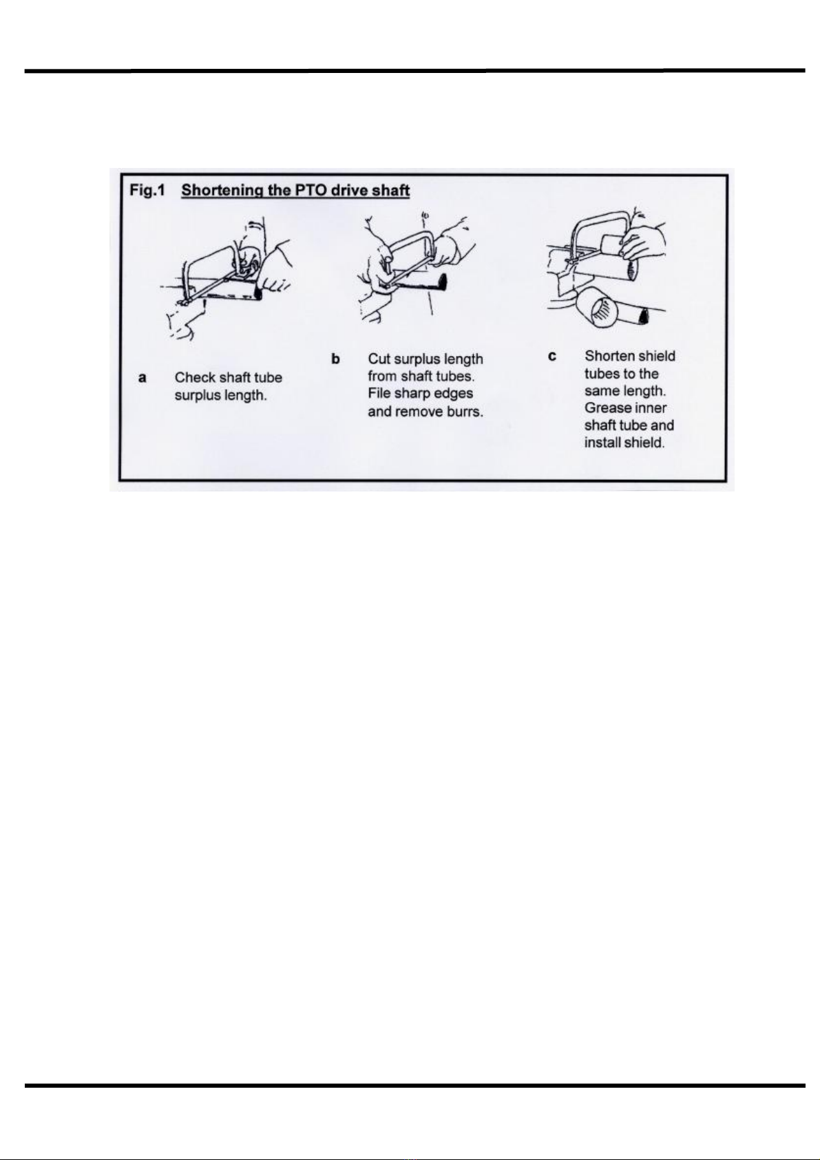
Before fitting the PTO for the first time, it may be necessary to adjust the length.
There should be maximum engagement of the sliding tubes without bottoming at the
shortest operation position. To check, first connect the mower to the tractor. Pull the
PTO shaft apart and connect to the tractor PTO output shaft and the gearbox input
shaft. Hold the half shafts next to each other in the shortest working position. If
necessary, shorten the inner and outer guard tubes equally (Fig. 1). Shorten the
inner and outer sliding profiles by the same length as the guard tubes. File all sharp
edges and remove burrs. Grease sliding profiles.
To fit the PTO, first clean and grease. Press pins on the yoke and simultaneously
push the PTO drive shaft onto PTO shaft of the tractor until pins engage.
The PTO shaft is fitted with a non-rotating safety guard. It should be secured to the
machine and tractor with the two retaining chains provided.
Connect the three hydraulic hoses, two wing hoses to a double acting service, with a
dump facility. This is particularly important for the spool valve that operates the wings
as, when in work the wings must be able to follow the ground contours. The 3rd hose
for the height ram only requires a single acting spool.

Spearhead MULTICUT 820
10
Setting Up Your Machine
Levelling –Front To Rear
Once coupled to the tractor, check the mower is cutting level from the front to the
rear of the machine. This is important to ensure each rotor will cut at the same height
(Fig. 3). The machine has adjustable tie bars that can be lengthened to lower the
front or shortened to raise the front of the machine by turning barrel nut (Fig. 2).
Once satisfied the mower is cutting level, tighten locking nuts.
Levelling –Wings LH & RH
With the machine in the working position and the wings folded down it may be
necessary to alter the height of the wing to ensure each rotor is cutting level.
Between each axle there is an adjustable link shortening this will raise the cutting
height of the wing rotor and blades. We recommend the wing is set 12-25mm higher
then the centre.
Warning
The machine is set at the factory with the centre deck 1” (25mm) higher at
the front and the wings ½” (12mm) higher to the centre section, when
mounted on the tractor drawbar at 16” (400mm).
When operating over uneven ground it is recommended to raise the front
of the machine by adjusting the tie bars to prevent scalping or damage to
the blades.

Spearhead MULTICUT 820
11
Setting Up Your Machine
Height
To adjust the minimum cutting height, first raise the machine to take the weight off
the centre height bar, lengthen the bar by turning the barrel and raising the minimum
height stop. Lower the machine onto this stop to the new set cutting height. This
adjustable barrel only controls the minimum cutting height, however the operator may
raise and lower the machine via the hydraulic cylinder whilst the machine is in
operation.
Wings
Before attempting to raise (Fig. 5) or lower the wings always ensure the machine is
on level ground. To unfold the wings from transport position, first charge/pressurise
the rams with oil before releasing the locking strap. Then power the wings over
centre with the aid of the double acting rams. Lower both wings on the ground and
release the hydraulic pressure by placing the spool in float position.
Warning
Do not pressurise the wing rams out once the wing wheels have
contacted the ground. This will cause unnecessary strain on
the machine and may result in damage not covered under
warranty.
Fig.5 Wings
Warning
Do not attempt to raise or lower the wings until the machine is on level
Ground. Never travel before both wings are either fully down or fully
Up and the transport strap is correctly fitted.

Spearhead MULTICUT 820
12
Operation
Once ready for work, raise the mower cutting height and slowly engage the PTO with
the tractor engine at low revs to prevent shock damage to the machine. Slowly
increase the engine revs to achieve the recommended PTO speed of 1000r.p.m. If at
any time serious vibration occurs, stop the engine immediately and check the
lades, following all safety precautions. Select a sensible forward speed bearing in
mind the density of growth, the terrain, and the available horsepower.
The quality of finish is determined by the forward speed, i.e. a slow speed will
produce a high quality of cut, where as faster forward speeds are used when high
output is first priority.
When in work, always ensure the hydraulic spool valve that operates the folding of
the wings is in float position to enable the wings to freely follow all contours of ground
(Fig. 6).
Whilst operating it is possible to continue working when turning as the 820 Rotary
Cutter is fitted with a constant velocity joint on PTO shaft. However take care not to
run the rear tractor wheel against the mower draw bar as this will result in serious
damage to the tractor, the mower and, in particular, the PTO shaft. The constant
velocity joint on the input PTO shaft, allows the PTO to be left in gear whilst turning
out of work, e.g. on the headlands. It is important not to turn sharply when the
machine is in work as this will over-strain and shorten the life of the constant
velocity joint.
When operating in confined areas it is possible to cut going backwards, but it is
advisable to slightly raise the machine, particularly if in scrub, where there is the risk
of hitting hidden solid obstacles obscured by dense undergrowth.
Always exercise particular care when operating over uneven ground surfaces. Do not
allow the blades and blade holder to frequently hit the ground.
Do not allow debris to build upon the cutting decks in dry conditions as this can be a
fire hazard, in wet conditions it will place unnecessary strain on the machine and may
foul the drive shaft causing damage.
Fig. 6 contours
of the ground
Warning
Do not run the machine with the wings raised. The risk of
debris and machine parts being ejected is greater as the
chain skirting is ineffective in this position.

Spearhead MULTICUT 820
13
Transportation
First disengage the PTO drive and ¾ raise the machine, fold the wings fully and
secure with transport strap (Fig. 7). Never transport along public highways with the
wings only supported by the hydraulics.
Please observe Public Highway Regulations, concerning the towing of implements,
and securely attach a registration and lighting board.
Warning
Avoid transporting machine at high speed over rough ground
Maximum speed on highway –20mph (30kph).
Fig. 7 Transportation position
Spearhead MULTICUT 820
14
Machine Protection
When the machine is delivered new, the slip clutch tensioning bolts will be
purposely left loose after initial PDI at Spearhead. This is to force the clutches
to be slipped and reset before the customer uses their machine for the first
time.
Refer to clutch settings on page 19/20/21.
To prevent gearbox damage all rotors are protected by slip clutches fitted to each of
the five drive shafts. When cutting in extreme conditions where stumps, rocks and
other such solid objects are likely to be found it is recommended that the operator
reduces the engine revs to allow the blades to pivot more easily when striking solid
objects, fit stump jumper plates to lower blade carriers, and procede with caution.
The clutch settings should not be altered without reference to Service and
Maintenance. Never over-tighten the pressure springs on the slip clutches (Fig. 8) as
this could result in severe damage to the gearbox and drive lines, as well as
invalidating the warranty.
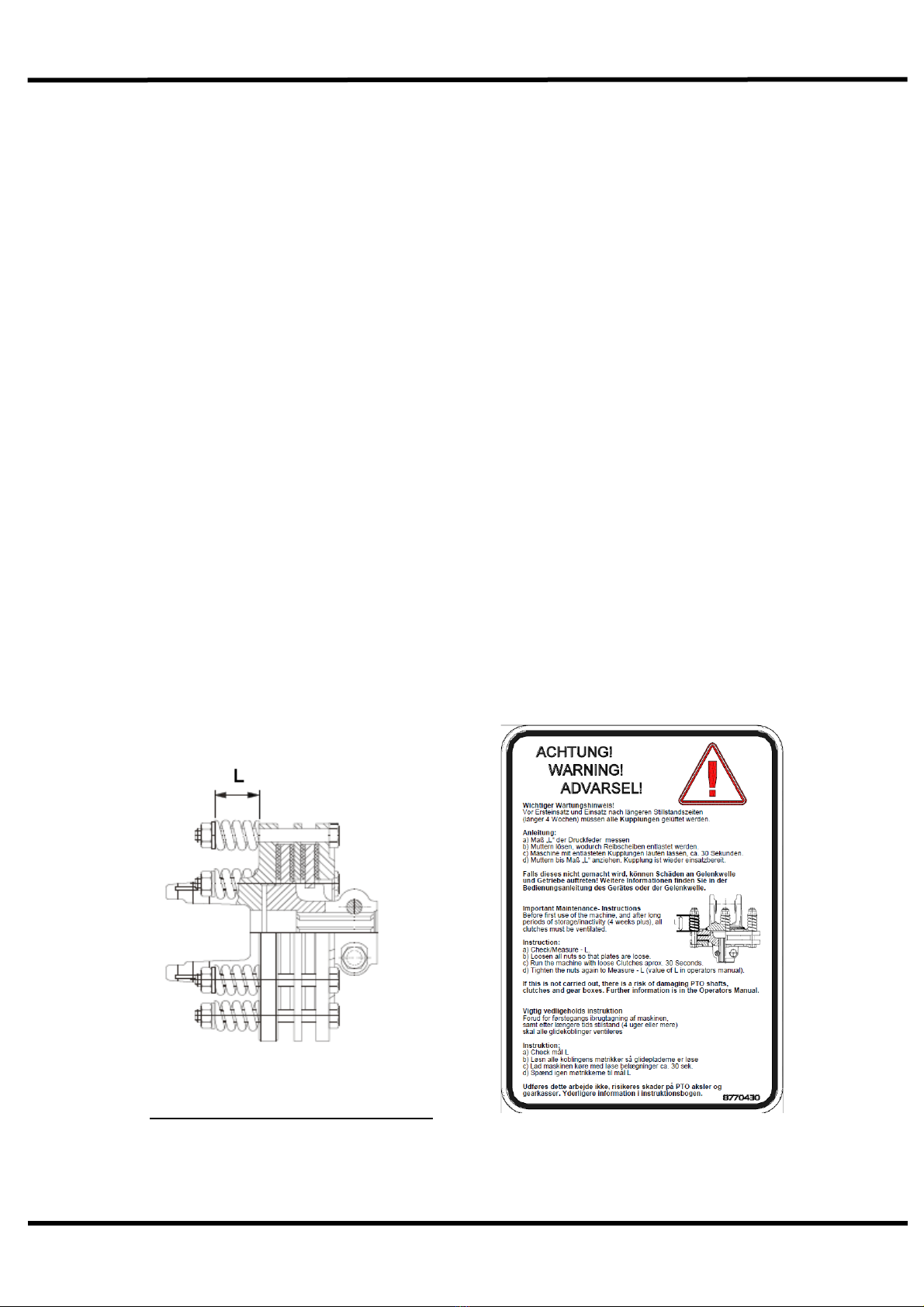
If the machine has been laid up for any length of time, there is a risk of the
clutch plates rusting and seizing together. Never operate the machine in this
condition, as there will be no protection to the driveline and gearboxes against
shock loading. To free the clutch plates first slacken all pressure spring bolts and run
up the machine for a short period, deliberately try to cause the clutch to slip. Finally
re-tighten the tension spring bolts to their original length, taking great care not to
over-tighten. Alternatively refer to page 19/20/21.
If in any doubt, consult Spearhead’s Service Department or your local Spearhead
Dealer for further advice.
Fig. 8b Slip Clutch (WALTERSCHEID)

Spearhead MULTICUT 820
15
Service & Maintenance
Safety First
Never leave the tractor seat without first disengaging the PTO and
stopping the engine.
Ensure all rotating parts have stopped turning.
Never attempt any repairs, maintenance, service or any other
checks with the machine carried on the tractor hydraulics.
Always fully lower to the ground, or securely prop the machine on
substantial servicing stands.
Always replace all guards and retaining chains after
servicing/maintenance completed.
It is imperative that the following checks are carried out in order not to
invalidate your warranty; these are carried out before the first
operation, after the first hour, then after 4 hours.
These checks are:
1. Wheel nuts and tyre pressure (60psi).
2. Gearbox bolts, including the splitter box.
3. Oils in all the 6 gearboxes.
4. Blade bolts are fully tightened and in particular the 5 castle headed
nuts on the 5 blade rotors.
5. Retaining bolts on the drive shafts.
6. Grease all points including drive shaft tubes.
7. After the first 50 hours drain and the gearboxes of oil. Replace
with EP90 gear oil.
8. All other nuts and bolt
Warning
Never carry out any servicing or maintenance work without
first disengaging the PTO and then stopping the tractor
engine before leaving the seat.
On delivery of your machine check that the dealer has
completed the P.D.I form, ensure the warranty registration
form is completed and returned.
Spearhead MULTICUT 820
16
Servicing & Maintenance
Daily
Grease all grease points, including rear axle pivot points (Fig. 9a), axle hinge
(Fig. 9c), wheel arms (Fig. 9b), and front draw bar pivot (Fig. 9f).
Check bolts are tight on all gearboxes.
Check condition of blades and blade bushes ensure all retaining bolts are
fully tight.
Check wheel nuts are tight.
Check tyre pressures - 60 P.S.I
Check gearbox oil, replenish with EP90 gear oil as necessary to the correct
level line on the dipsticks provided with each gearbox.
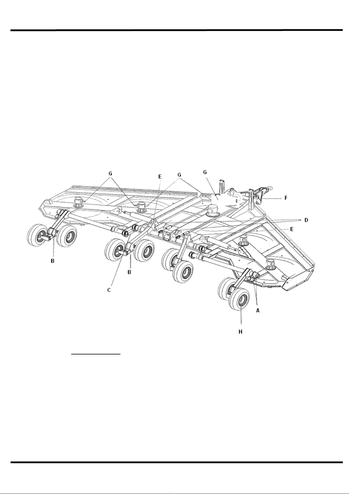
Fig.9. Greasing points
A. Rear axle pivot point.
B. Wheel arm pivot point.
C. Axle adjuster.
D. Height stop.
E. Hydraulic rams
F. Drawbar
G. Drive shaft
H. Wheel bearings

Spearhead MULTICUT 820
17
Service & Maintenance –Every 8 hours
Dismantle and clean the main input P.T.O shafts sliding surfaces and re-
grease; failure to do this will result in serious damage to the splitter gearbox.
Grease all universal joints, (Fig. 10) paying particular attention to the constant
velocity joint. If under-greased this constant velocity joint will soon fail.
Grease the wing drive shaft tubes, (note the hole in the plastic tubing for
access).
Lubricate the retaining collar on all the drive shaft guards (Fig. 10).
Grease PTO inner tube and push pins (Fig. 10).
Check all bolts are tightened to the correct Torque (Fig.11).
Torque Settings
The Torque figures given below are recommended maximum settings only.
Size:
Tensile strength:
Description:
Torque setting:
Nm.
M16
8.8
Gearbox bolts
280
M24
8.8
Axle clamps
750
M24
8.8
Blade bolts
540-800
Wheel nuts
270
For maximum life and performance, the CV body must be greased regularly. Lubricate with
the driveline in a straight position - up to 30 pumps of grease may be required.
The metal drive tubes must be greased to operate properly.
Shielding is subject to damage from abuse and weathering. Replace all damaged
components and all shielding removed during maintenance.
Do not use PTO adapters with CV drivelines. Replace special taper pin bolts only with
genuine OEM parts, periodically check tightness of nuts.
Fig. 10
Primary Input Shaft

Spearhead MULTICUT 820
18
Servicing & Maintenance
Regularly
Check there is no wrapping of string, plastic, grass or other debris between
rotor boss and gearbox oil seal.
Inspect gearbox seals for leaks.
Clear grass and other debris from the deck.
Regularly check the rotor boss retaining castle nut for tightness. First remove
the split pin, select the correct size socket in 3/4” drive and fully tighten the
nut. When replacing the split pin, do not slacken the nut to align the hole,
always tighten. Failure to regularly check this nut will result in serious wear to
hub, which is expensive to repair.
It is most important that all gearbox bolts are regularly checked to be
very tight. When the machine is new there will be a ‘bedding in’ period
where very frequent checking is important.
Blades
Caution! When carrying out maintenance work on or near the blades be careful
of free-swinging blades over-centering and falling. It is recommended that
protective clothing including hardhat and goggles are worn.
The blades can be re-sharpened by grinding the cutting edges, care must be taken
that the blades are of the same weight and length after grinding. Do not overheat
when grinding as this will affect the hardness of the blades. All the blades are free
swinging and swivel on hardened steel bushes, which are replaceable. When
replacing blades, it is important that blades are replaced in sets, in order to retain
balance of the rotor. Bushes must be replaced when new blades are to be fitted.
If the blades are showing any signs of severe wear, damage or cracking, they must
be replaced immediately. Never attempt to weld the blades, as this will make them
very brittle thus extremely dangerous. Do not take risks with the cutting blades - if in
doubt, replace.
Spearhead MULTICUT 820
19
Servicing & Maintenance
Slip Clutch Settings
We recommend that friction clutches be stored in a dry place with the spring pressure
released. In use, the compression of the spring has to be adjusted periodically to
compensate for lining wear and to maintain the setting at the original value.
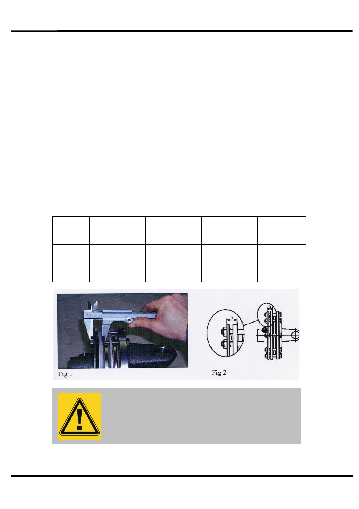
Check the condition of the friction discs before use and following periods of storage.
Release the tension from the spring, turn the clutch while holding the gearbox shaft
stationary. Adjust the spring compression to the original setting (fig. 1).
Following seasonal use, unload the spring tension and stone clutch assembly in a dry
place. Check condition of friction linings and reset spring compression to original
height before use.
Should the assembly overheat due to frequent or prolonged clutch slipping, dismantle
for inspection. The original thickness of the lining is 3.2mm, replace them when worn
to 2.5mm. Clean up all contact surfaces and replace any damaged components
before assembly.
BONDIOLI Manufacture (Belleville Spring)
Fig. No.
Position
Part No.
Setting ‘h’
Machine
2
Centre
5770043
18.5 mm (fig 1)
820
2
Inner wing
5770213
19 mm (fig 1)
820
2
Outer wing
5770214
18 mm (fig 1)
820
Warning
The slip clutch is there to protect the gearbox. If the
blades strike a large obstacle they may get damaged or
break - avoid these conditions.
Spearhead MULTICUT 820
20
Servicing & Maintenance
Slip Clutch Settings
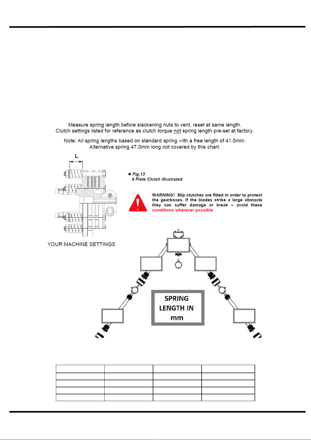
WALTERSCHEID Manufacture (Coil Spring)
Check the condition of the friction discs before use and following periods of storage.
Release the tension from the spring, turn the clutch while holding the P.T.O to ensure
hub is not seized to linings.
Clutch settings below are for reference only. Measured spring lengths should be
used first.
Position
Part No.
Setting ( L )
Machine
Centre
5770441
35.0 mm
820
Centre
5770468
38.1 mm
820
Inner wing
5770442
37.8 mm
820
Outer wing
5770443
37.5 mm
820
Table of contents
Other Spearhead Tractor Accessories manuals


