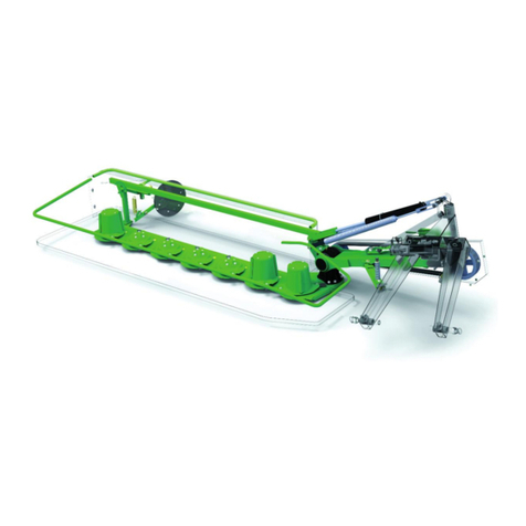
SaMASZ KT 260 H User manual

SaMASZ Sp. z o.o.
Poland, 15-161 Białystok, ul. Trawiasta 15
Established – 1984
NIP 966-159-29-76
tel. (+48) (85) 654 45 84
Fax (+48) (85) 664 70 41
E-mail: samasz@samasz.pl
www.samasz.pl
OPERATION MANUAL
REAR DISC MOWER WITH
CENTRAL SUSPENSION
KT 260 H - 2,6 m
KT 260 - 2,6 m
KT 260 S H - 2,6 m
KT 260 S - 2,6 m
KT 260 W H
- 2,6 m
KT 260 W
- 2,6 m
KT 300 H - 3,0 m
KT 300 - 3,0 m
KT 300 S H - 3,0 m
KT 300 S - 3,0 m
KT 300 W H
- 3,0 m
KT 300 W
- 3,0 m
KT 340 H - 3,4 m
KT 340 - 3,4 m
KT 340 S H - 3,4 m
KT 340 S - 3,4 m
IN541EN001
14.01.2011
VERSION NO 1
Serial No:

IT IS FORBIDDEN
TO TURN ON THE MOWER
BEFORE THE MOWER IS IN
WORKING POSITION
IT IS FORBIDDEN
TO RETURN THE MOWER
INTO TRANSPORTING POSITION
BEFORE THE CUTTING DISCS
COME TO A COMPLETE STOP
IT IS FORBIDDEN
TO OPERATE THE MOWER
IF THERE ARE PEOPLE
PRESENT WITHIN
50 M OF THE MOWER
Tilting the mower in the direction of travel by app.
0° - 5° is recommended. Mowing in the vertical
position is allowed. Tilting the mower in the opposite
direction will result in permanent damage to the
cutting
bar.

Operating manual
Rear disc mowers with central suspension
- with hydro-pneumatic or spring suspension
- 1 -
Table of contents page
1.
DEVICE IDENTIFICATION ......................................................................................................2
2.
INTRODUCTION.........................................................................................................................2
3.
INTENDED USE ...........................................................................................................................3
3.1. Technical data............................................................................................................................................. 4
3.2. Construction and operation......................................................................................................................... 6
3.3. Equipment and spare parts........................................................................................................................ 12
4.
SAFETY RULES AND WARNINGS........................................................................................13
4.1. General rules............................................................................................................................................. 13
4.2. Transport................................................................................................................................................... 15
4.2.1. Placing the mower onto a transport vehicle....................................................................................... 15
4.3. Operating elements................................................................................................................................... 16
4.4. The articulated telescoping shaft .............................................................................................................. 16
4.5. Residual risk ............................................................................................................................................. 16
4.6. Warning signs and their meanings............................................................................................................ 18
4.7. Operation and construction of the hydraulic safety device....................................................................... 24
5.
OPERATION OF THE MOWER..............................................................................................25
5.1. Connecting the mower to the tractor......................................................................................................... 25
5.2. Connecting the articulated telescopic shaft (ATS) ................................................................................... 25
5.3. Preparing the mower for operation – mowers with hydro – pneumatic suspension................................. 26
5.3.1. Gas pressure in the accumulator and in the entire system for each mower model............................27
5.4. Preparing the mower for operation – mowers with spring suspensions ................................................... 27
5.5. Operating the mower ................................................................................................................................ 27
5.5.1. Basic mowing information ................................................................................................................28
5.5.2. Mower positioning during directional changes ................................................................................. 29
5.6 Preparing the mower for transport............................................................................................................. 29
5.7. Preparing the mower for transport on public roads. ................................................................................. 30
5.8. Changing the mower position from transport to operating position......................................................... 32
6.
ASSEMBLY AND SETTINGS...................................................................................................33
6.1. Installing the cutting blades...................................................................................................................... 33
6.2. Blade replacement..................................................................................................................................... 33
6.3. Setting mowing width............................................................................................................................... 34
6.4. Setting mowing height.............................................................................................................................. 35
6.5. Use and adjustment of the load reducing chain........................................................................................ 35
6.6. Adjustment of the gap between the cover and the roller of the scarifier.................................................. 36
6.7. Replacement of the flails of the scarifier.................................................................................................. 36
6.8. Adjustment of the pressure between the rollers........................................................................................ 37
6.9. Maintenance.............................................................................................................................................. 37
6.9.1. Checking the blades and blade holders.............................................................................................. 37
6.9.2. Checking the tautness of the chain of the chain drive of the scarifier and rollers............................. 38
6.9.3. Everyday maintenance....................................................................................................................... 38
6.9.4. End of season maintenance................................................................................................................ 38
7.
LUBRICATION...........................................................................................................................39
7.1. The cutting bar.......................................................................................................................................... 39
7.2. Miter gears................................................................................................................................................ 39
7.3. Roller gear. ............................................................................................................................................... 40
7.4. Chain drives of the roller and the scarifier................................................................................................ 41
7.5. Bearings and joints.................................................................................................................................... 42
8.
MALFUNCTIONS AND THEIR CORRECTION..................................................................43
9.
MOWER REPAIR AND DISPOSAL........................................................................................44
10.
WARRANTY CARD...................................................................................................................44
11.
WARRANTY CONDITIONS ....................................................................................................45
11.1. Zasady postępowania gwarancyjnego..................................................................................................... 45
11.2. Record of warranty repairs ..................................................................................................................... 46

Operating manual
Rear disc mowers with central suspension
- with hydro-pneumatic or spring suspension
- 2 -
1. DEVICE IDENTIFICATION
The mower identification plate is affixed permanently to the body of the mower shown on Pict.1
Pict. 1. Location of the identification plate. Pict. 2. Identification plate.
The identification plate contains:
−
full name of the manufacturer,
−
mower serial number,
−
mower model,
−
date of manufacture,
−
weight
−
quality control mark,
−
the CE symbol signifies that the mower
conforms to the 2006/42/WE Directive
and harmonized standards.
−
the MADE IN POLAND sign
ATTENTION:
Detailed information about the mower can be obtained from the manufacturer or
distributor of the machine.
2. INTRODUCTION
•
This instruction should be regarded as part of the basic equipment of the mower. When
the mower is turned over to a different user it should be in working condition and accompanied
by this instruction manual and all other basic equipment it should posses.
•
Before operating this mower the user should first completely read the instructions in this
manual and should be familiar with general safety rules.
•
The mower has been manufactured in accordance with all safety norms.
•
Adhering to the instruction manual guarantees the user full safety during operation.
•
In the event of any doubts regarding starting and operation of the mower please contact
the manufacturer.
•
The instruction manual is an integral part of the equipment of the mower.
GENERAL WARNING
During the operation of the mower please observe all the warnings and
safety rules which are marked with this sign in the instruction manual.
WARNING:
It is forbidden to operate the mower without previously reading the instruction
manual, and for it to be used by persons not authorized to drive farm tractors,
especially children
.
KT 300 H
KOSIARKA DYSKOWA

Operating manual
Rear disc mowers with central suspension
- with hydro-pneumatic or spring suspension
- 3 -
3. INTENDED USE
1. A mower without crop scarifier or rollers is equipped with the „Perfect Cut” cutting bar
or optionally with the „Heavy Duty” cutting bar. In table 1 the mowing height differences,
depending on the tilt angle of the cutting bar are shown.
Table 1. Mowing height depending on the kind of the cutting bar and its tilt angle.
„Perfect Cut” cutting bar
No tilt 3° tilt 5° tilt
„Heavy Duty” cutting bar
No tilt 3° tilt 5° tilt
•
The rear mounted disc mower is intended to mow green fodder: grass, alfalfa and such on
permanent grassland (pastures), on crop fields without rocks, and to form loose rows of cut
fodder. The pasture or field being mown should be even, best if prepared by rolling. In
the event of a majority of tall grass the first and second mowing should be done at a height
of 60-70 mm, while with a majority of short grasses at a height of 50 mm. The last mowing
should be done a little higher - at 70-80 mm from the ground.
2. A mower with the crop scarifier/rollers is equipped with the „Perfect Cut” cutting bar or the
optional „Heavy Duty” cutting bar.
•
The rear mounted disc mower with crop scarifier/rollers is intended to mow green fodder:
grass, alfalfa and such on permanent grassland (pastures), on crop fields without rocks, and
to form loose rows of cut fodder. As a result of the passing of the layers of the green fodder
through the flails or rollers the grass stems are broken and a layer of wax is removed. This
facilitates and speeds up the drying process of the fodder by approximately 30 to 40%.
The use of rollers is especially recommended when mowing legumes such as alfalfa.
Rollers are particularly recommended for mowing grass legume such as alfalfa. The pasture
or field being mown should be even, best if prepared by rolling. This is especially true of
mowers with rollers as they tolerate rocks with a diameter of a few centimeters. If a larger
stone is picked up stop and remove it as it could cause damage of the discs. With a majority
of tall grasses the first and second mowing should be done at a height of 6-7 cm, while with
a majority of short grasses at a height of 5 cm. The last mowing should be done a little
higher - at 7-8 cm from the ground.

Operating manual
Rear disc mowers with central suspension
- with hydro-pneumatic or spring suspension
- 4 -
WARNING:
It is forbidden to use the mower for purposes other than those listed in this
instruction. Using the mower for other purposes will be classified as use not
according with the intended use and could exclude the manufacturer from
responsibility from any resulting damages. The mower should be used, serviced
and repaired only by persons familiar with its characteristics and with safety
regulations. Unauthorized modification of the mower may release
the manufacturer from responsibility for any resulting malfunctions or damages.
3.1. Technical data
1. The KT mowers can be generally divided into two groups:
•
mowers with hydro - pneumatic suspension
•
mowers with spring suspensions
2. The hydro – pneumatic suspension replaces the traditional springs which significantly
improves the comfort of mower operation. Thanks to this solution the operator can, using
the hydraulic system of the tractor quickly set the pressure of the cutting bar on the ground.
Additionally this system is integrated with the hydraulic safety device.
3. The technical specifications of the groups mentioned above are presented below.
Table 2. Technical data – Mowers with hydro – pneumatic suspension
Mower type: KT 260 H KT 300 H KT 340 H
Mowing width 2.60 m 3.00 m 3.40 m
Number of blades [pcs] 12 (2 x 6) 14 (2 x 7) 16 (2 x 8)
Tractor PTO speed 1000 rpm
Tractor power 50 kW
(70 KM) 58 kW
(80 KM) 65 kW
(90 KM)
Tractor class od 2.0 od 2.0 od 2.0
Working capacity ~ 2.8 ha/h ~ 3.5 ha/h ~ 4.0 ha/h
Transport height 3100 3500 3900
Transport width 2.0 m 2.0 m 2.0 m
Operating width 4.7 m 5.1 m 5.5 m
Weight 900 kg 1000 kg 1080 kg
Articulated telescopic shaft
with unidirectional clutch 540 Nm
Line cutting speed 86.2 m/s
Disc rotational speed 3078 rpm
Mower type: KT 260 S H KT 300 S H KT 340 S H KT 260 W H KT 300 W H
Mowing width 2.60 m 3.00 m 3.40 m 2.60 m 3.00 m
Number of blades [pcs] 12 (2 x 6) 14 (2 x 7) 16 (2 x 8) 12 (2 x 6) 14 (2 x 7)
Tractor PTO speed 1000 rpm
Tractor power 58 kW
(80 KM) 66 kW
(90 KM) 75 kW
(100 KM) 58 kW
(80 KM) 66 kW
(90 KM)
Tractor class 2.0 2.0 2 2.0 2.0
Working capacity ~ 2.8 ha/h ~ 3.5 ha/h ~ 4.0 ha/h ~ 2.8 ha/h ~ 3.5 ha/h
Transport height 2.0 m 2.0 m 2.0 m 2.0 m 2.0 m
Operating width 4.7 m 5.1 m 5.5 m 4.7 m 5.1 m
Weight 1080 kg 1180 kg 1290 kg 1160 kg 1260 kg
S – Mower with crop scarifier W – Mower with crop rollers

Operating manual
Rear disc mowers with central suspension
- with hydro-pneumatic or spring suspension
- 5 -
Table 3. Technical data – Mowers with spring suspension
Mower type: KT 260 KT 300 KT 340
Mowing width 2.60 m 3.00 m 3.40 m
Number of blades [pcs] 12 (2 x 6) 14 (2 x 7) 16 (2 x 8)
Tractor PTO speed 1000 rpm
Tractor power 50 kW
(70 KM) 58 kW
(80 KM) 65 kW
(90 KM)
Tractor class from 2.0 from 2.0 from 2.0
Working capacity ~ 2.8 ha/h ~ 3.5 ha/h ~ 4.0 ha/h
Transport height 3100 3500 3900
Transport width 2.0 m 2.0 m 2.0 m
Operating width 4.7 m 5.1 m 5.5 m
Weight 950 kg 1040 kg 1110 kg
Articulated telescopic shaft with
unidirectional clutch 540 Nm
Line cutting speed 86.2 m/s
Disc rotational speed 3078 rpm
Mower type: KT 260 S KT 300 S KT 340 S KT 260 W KT 300 W
Mowing width 2.60 m 3.00 m 3.40 m 2.60 m 3.00 m
Number of blades [pcs] 12 (2 x 6) 14 (2 x 7) 16 (2 x 8) 12 (2 x 6) 14 (2 x 7)
Tractor PTO speed 1000 obr/min
Tractor power 58 kW
(80 KM) 66 kW
(90 KM) 75 kW
(100 KM) 58 kW
(80 KM) 66 kW
(90 KM)
Tractor class 2.0 2.0 2 2.0 2.0
Working capacity ~ 2.8 ha/h ~ 3.5 ha/h ~ 4.0 ha/h ~ 2.8 ha/h ~ 3.5 ha/h
Transport width 2.0 m 2.0 m 2.0 m 2.0 m 2.0 m
Operating width 4.7 m 5.1 m 5.5 m 4.7 m 5.1 m
Weight 1170 kg 1270 kg 1290 kg 1250 kg 1350 kg
Articulated telescopic shaft with
unidirectional clutch 540 Nm
Linea cutting speed 86,2 m/s
Disc rotational speed 3078 obr./min
S – Mower with crop scarifier W – Mower with crop rollers

Operating manual
Rear disc mowers with central suspension
- with hydro-pneumatic or spring suspension
- 6 -
3.2. Construction and operation
Pict. 3a. General view of the rear mounted disc mower with hydro – pneumatic suspension.
•
The suspension frame (1) allows the mower to be connected to the three point hitch of
the tractor.
•
The power from the PTO of the tractor is transferred by the drive shaft (14), the miter gear (3)
to the drive shaft (7), which through the miter gear (8) powers the cutting bar (4).
•
On the cutting bar there are discs with two cutting blades each.
•
The hydraulic lifting actuator (2), as well as the hydro-pneumatic suspension, powered by
the external hydraulic system of the tractor and the hydraulic accumulator (12), is used to
place the mower in the operating position.
•
The main frame on which the cutting bar is mounted is supported by the hydro-pneumatic
suspension (10).
•
Thanks to the above mentioned suspension we can adjust the pressure of the machine on
the ground by adjusting the pressure of the system.
•
The mower is also equipped with a rotational actuator (9), which has two functions. The first
one is the ability to fold the mower backwards which, in many cases, significantly simplifies
transport, while the second is the factory calibrated hydraulic safety device (11).
•
The crop gatherers (5) are also installed on the main frame.
1 – Suspension frame
2 – Lifting actuator
3 – Miter gear I
4 – Cutting bar
5 – Crop gatherers
6 – Safety cover
7 – PTO I
8 – Miter gear II
9 – Rotational actuator
10 – Hydro-pneumatic suspension
11 – Hydraulic safety device
12 – Hydraulic accumulator
13 – Support foot
14 – PTO II
6
4
2
8
10
11
1
7
3
13
12
9
14
5
5

Operating manual
Rear disc mowers with central suspension
- with hydro-pneumatic or spring suspension
- 7 -
Pict. 3b. General view of the rear mounted disc mower
•
The suspension frame (1) allows the mower to be connected to the three point hitch of
the tractor.
•
The power from the PTO of the tractor is transferred by the drive shaft (12), the miter gear
(3) to the drive shaft (7), which through the miter gear (8) powers the cutting bar (4).
•
On the cutting bar there are discs with two cutting blades each.
•
The hydraulic lifting actuator (2) powered by the external hydraulic system of the tractor is
used to place the mower into operating position. The main frame on which the cutting bar is
mounted is supported by the spring suspension (9).
•
The mower is also equipped with a rotational actuator (10), which has two functions.
The first one is the ability to fold the mower backwards which, in many cases, significantly
simplifies transport, while the second is the factory calibrated hydraulic safety device (11).
•
The crop gatherers (5) are also installed on the main frame.
1 – Suspension frame
2 – Lifting actuator
3 – Miter gear I
4 – Cutting bar
5 – Crop gatherers
6 – Safety cover
7 – PTO I
8 – Miter gear II
9 – Spring suspension
10 – Rotational actuator
11 – Hydraulic safety device
12 – PTO II
13 – Support foot
3
7
10
13
12
1
11
2
6
5
4
5
8
9

Operating manual
Rear disc mowers with central suspension
- with hydro-pneumatic or spring suspension
- 8 -
Pict. 3c. General view of the rear mounted disc mower with hudro – pneumatic suspension and with crop scarifier.
•
The suspension frame (1) allows the mower to be connected to the three point hitch of
the tractor.
•
The power from the PTO of the tractor is transferred by the drive shaft (16), the miter gear
(3) to the drive shaft (7), which through the miter gear (8) powers the cutting bar (4).
Additionally power from the PTO of the tractor is transferred through the miter gear (8),
the drive shaft (7), miter gear (9) and the chain drive (15) to the crop scarifier (3).
•
On the cutting bar there are discs with two cutting blades each.
•
The hydraulic lifting actuator (2), as well as the hydro-pneumatic suspension, powered by
the external hydraulic system of the tractor and the hydraulic accumulator (12), is used to
place the mower in the operating position.
•
The main frame on which the cutting bar is mounted is supported by the hydro-pneumatic
suspension (10). Thanks to the above mentioned suspension we can adjust the pressure of
the machine on the ground by adjusting the pressure of the system.
•
The mower is also equipped with a rotational actuator (9), which has two functions. The first
one is the ability to fold the mower backwards which, in many cases, significantly simplifies
transport, while the second is the factory calibrated hydraulic safety device (11).
•
The crop guides (5) are installed on the upper cover of the scarifier.
1 – Suspension frame
2 – Lifting actuator
3 – Crop scarifier
4 – Cutting bar
5 – Crop guides
6 – Safety cover
7 – PTO I
8 – Miter gear I
9 – Miter gear II
10 – Hydro pneumatic suspension
11 – Rotational actuator
12 – Hydraulic safety device
13 – Hydraulic accumulator
14 – Support feet
15 – Chain drive
16 – PTO II
1
12
10
9
2
6
11
16
14
13
8
7
4
15
5
3
5
14

Operating manual
Rear disc mowers with central suspension
- with hydro-pneumatic or spring suspension
- 9 -
Pict 3d. General view of the disc mower with crop scarifier.
•
The suspension frame (1) allows the mower to be connected to the three point hitch of
the tractor.
•
The power from the PTO of the tractor is transferred by the drive shaft (15), the miter gear (7)
to the drive shaft (9), which through the miter gear (8) powers the cutting bar (4). Additionally
power from the PTO of the tractor is transferred through the miter gear (7), the drive shaft (9),
miter gear (8) and the chain drive (11) to the crop scarifier (3).
•
On the cutting bar (4) there are discs with two cutting blades each.
•
The hydraulic lifting actuator (2) powered by the external hydraulic system of the tractor is
used to place the mower into operating position.
•
The main frame on which the cutting bar is mounted is supported by the spring suspension
(12).
•
The mower is also equipped with a rotational actuator (13), which has two functions. The first
one is the ability to fold the mower backwards which, in many cases, significantly simplifies
transport, while the second is the factory calibrated hydraulic safety device (14).
•
The crop guides (5) are installed on the upper cover of the scarifier.
1 – Suspension frame
2 – Lifting actuator
3 – Crop scarifier
4 – Cutting bar
5 – Crop guides
6 – Safety cover
7 – Miter gear I
8 – Miter gear II
9 – PTO I
10 – Support feet
11 – Chain drive
12 – Spring suspension
13 – Rotational actuator
14 – Hydraulic safety device
15 – PTO II
11
7
4
9
10
5
3
5
10
10
13
1
15
14
12
2
6
8

Operating manual
Rear disc mowers with central suspension
- with hydro-pneumatic or spring suspension
- 1 0 -
Pict 3e. General view of the rear mounted disc mower with hydro – pneumatic suspension and crop rollers.
•
The suspension frame (1) allows the mower to be connected to the three point hitch of
the tractor.
•
The power from the PTO of the tractor is transferred by the drive shaft (16), miter gear (8) to
the drive shaft (7), which through the miter gear (9) powers the cutting bar (4). Additionally
power from the PTO of the tractor is transferred through the miter gear (8), the drive shaft
(7), miter gear (9) and the chain drive (15) to the crop rollers (3).
•
On the cutting bar (4) there are discs with two cutting blades each.
•
The hydraulic lifting actuator (2), as well as the hydro-pneumatic suspension, powered by
the external hydraulic system of the tractor and the hydraulic accumulator (13), is used to
place the mower in the operating position.
•
The main frame on which the cutting bar is mounted is supported by the hydro-pneumatic
suspension (10). Thanks to the above mentioned suspension we can adjust the pressure of
the machine on the ground by adjusting the pressure of the system.
•
The mower is also equipped with a rotational actuator (11), which has two functions.
The first one is the ability to fold the mower backwards which, in many cases, significantly
simplifies transport, while the second is the factory calibrated hydraulic safety device (12).
•
The crop guides (5) are installed on the upper cover of the scarifier.
1 – Suspension frame
2 – Lifting actuator
3 – Crop rollers
4 – Cutting bar
5 – Crop guides
6 – Safety cover
7 – PTO I
8 – Miter gear I
9 – Miter gear II
10 – Hydro pneumatic suspension
11 – Rotational actuator
12 – Hydraulic safety device
13 – Hydraulic accumulator
14 – Support foot
15 – Chain drive
16 – PTO II
2
5
5
8
10
9
12
3
14
7
4
15
1
13
11
6
16

Operating manual
Rear disc mowers with central suspension
- with hydro-pneumatic or spring suspension
- 1 1 -
Pict 3f. General view of the rear mounted disc mower with crop rollers.
•
The suspension frame (1) allows the mower to be connected to the three point hitch of
the tractor.
•
The power from the PTO of the tractor is transferred by the drive shaft (15) miter gear (7) to
the drive shaft (9), which through the miter gear (8) drives the cutting bar (4). Additionally
power from the PTO of the tractor is transferred through the miter gear (7), drive shaft (9),
miter gear (8) and the chain drive (11) to the crop rollers (3)
•
On the cutting bar (4) there are discs with two cutting blades each.
•
The hydraulic lifting actuator (2) powered by the external hydraulic system of the tractor is
used to place the mower in the operating position.
•
The main frame on which the cutting bar is mounted is supported by the spring suspension
(12).
•
The mower is also equipped with a rotational actuator (13), which has two functions. The first
one is the ability to fold the mower backwards which, in many cases, significantly simplifies
transport, while the second is the factory calibrated hydraulic safety device (14).
•
The crop guides (5) are installed on the upper cover of the scarifier.
Comprehensively tested construction and proper choice of materials ensure high reliability and
durability of our products
1 – Suspension frame
2 – Lifting actuator
3 – Crop rollers
4 – Cutting bar
5 – Crop guides
6 – Safety cover
7 – Miter gear I
8 – Miter gear II
9 – PTO I
10 – Support foot
11 – Chain drive
12 – Spring suspension
13 – Rotational actuator
14 – Hydraulic safety device
15 – PTO II
10
7
9
4
11
5
3
5
6
2
12
14
1
15
8
13

Operating manual
Rear disc mowers with central suspension
- with hydro-pneumatic or spring suspension
- 1 2 -
3.3. Equipment and spare parts
The mowers are sold with the following standard equipment:
•
a warranty card,
•
an operating manual and a catalogue of spare parts,
•
cutting blades: KT 260 and KT 260 H – 1 pack, KT 300 – 340 and KT 300 H – 340 H –
2 packs,
•
a special wrench for blade replacement,
•
an articulated telescopic shaft with unidirectional clutch.
Additional equipment (to be purchased separately):
•
safety board with lights and reflectors,
•
portable reflective triangle,
Table 4. Articulated telescoping shaft installed on the mower.
Mower Power
Length Moment
Symbol Clutch Manufactur
er Remarks
kW mm Nm
KT 260 H; KT 260
KT 300 H; KT 300
KT 340 H; KT 340
55 610-823
540 CS5N081F
X
007007PT - Bondioli-
Pavesi Shaft installed
KT 260 S H; KT 260 S
KT 260 W H; KT 260 W
KT 300 S H; KT 300 S
KT 300 W H; KT 300 W
KT 340 S H; KT 340 S
Table 5. Articulated telescoping shaft to connect the mower to the tractor
Mower Power
Length Moment
Symbol Clutch Manufactur
er Remarks
kW mm Nm
KT 260 H; KT 260
KT 300 H; KT 300
KT 340 H; KT 340
55 860-1198
540 CS5N101C
E
0071A1A
Unidirectina
l friction
clutch
Bondioli-
Pavesi
Shaft connecting
tractor and
mower
KT 260 S H; KT 260 S
KT 260 W H; KT 260 W
KT 300 S H; KT 300 S
KT 300 W H; KT 300 W
KT 340 S H; KT 340 S
Pict
4 directions.
Shaft end without
clutch – Connect to
tractor
Shaft end with unidirectional
right clutch –
Connect to the
mower
50h
50h
50h
50h
8h
8h
Pict 4. Shaft lubricating instructions and connecting directions

Operating manual
Rear disc mowers with central suspension
- with hydro-pneumatic or spring suspension
- 1 3 -
WARNING:
The frequency of lubrication of the articulated telescoping shaft should be
carefully adhered to. Points shown on Pict. 4 should be lubricated every 50
hours. The articulated telescoping shaft should also be lubricated before and
after longer periods of disuse.
•It is possible to use shafts with similar technical parameters from different manufacturers after
consulting SaMASZ.
ATTENTION:
Additional equipment must be purchased separately.
•
The manufacturer will equip the mower with connecting elements (brackets and supports)
used to install required lamps and signs. Integrated lamps and reflectors are mounted on
the warning board.
Congratulations on your mower purchase and we know you will be satisfied from its use.
4. SAFETY RULES AND WARNINGS
4.1. General rules
•
The front axle of the driving tractor should be adequately loaded to maintain balance. If
necessary use front wheel weights.
•
All manipulation of the hydraulic hoist control lever should be made only from the driving seat,
operating the hoist while outside the tractor is forbidden.
•
In tractors with electro-hydraulic control system (EHR) the hoist is operated with a button
outside the cabin of the tractor. During operation please remain especially cautious.
•
When changing the mower position from operating to transporting the AT shaft should be
removed completely or at least on the end connected to the PTO of the tractor.
•
Operating the mower without covers or the apron is forbidden. The mower should also not be
operated with a damaged or raised apron (there is a danger of the mower throwing hard
objects).
•
Mowing can only be started after the power take-off reaches a nominal speed of 1000 rpm,
•
The power take-off cannot exceed speeds of 1050 rpm.
•
There should be a safe distance between the mower and people, a minimum of 50 m. Utmost
care should be maintained while working in the vicinity of roads and streets.
•
Any servicing or adjusting of the mower must be done only after the engine and cutting discs
have stopped.
•
The condition of blade holders must be periodically checked. Any damaged or worn holders
must be replaced.
•
During transport on public roads all traffic laws regarding lighting and additional equipment
for the mower must be observed. During transport the mower should be equipped with
the removable light board and the triangular safety sign.
WARNING:
Any maintenance or repair of the mower should be done with the tractor engine
off, the cutting bar resting on the ground and all rotating parts must be at rest.

Operating manual
Rear disc mowers with central suspension
- with hydro-pneumatic or spring suspension
- 1 4 -
WARNING:
It is forbidden for children to come in contact with the machine during
operation and while at rest.
•
During any repair being performed while the mower is lifted on the TPH, the mower should be
secured with a support or a chain so that it does not fall.
•
The condition of bolts and other connectors should be periodically checked. Operation of
the mower with damaged connectors is unnaceptable.
•
The regulator line changing the position of the mower should have enough slack and be
properly installed in the cabin of the tractor.
•
During operation of the mower the Regulation of the Farm Ministry and Food Economy
(Rozporządzenie Ministra Rolnictwa i Gospodarki Żywnościowej) from 12-01-1998 dealing
with safety and hygiene during the operation of tractors, machinery, tools and equipment used
for farming (Dz. U. nr 12/98 poz. 51), should be observed.
•
The tractor used with the mower should be equipped with a driver's cabin.
•
The mower cannot be used if the tractor has not been properly balanced.
•
Never start the mower if it is in the up position.
•
Never start the mower if people or animals are in the proximity of the mower.
•
Never lift the tarpaulin apron before the rotating parts of the mower come to a complete stop.
The tractor engine must be turned off.
•
Observe all safety signs, warnings or warning signs placed on the mower.
•
Before turning on the tractor make sure that all drives are disengaged and the hydraulic control
lever is in neutral.
•
Do not leave a running tractor without supervision. Before leaving the tractor turn off
the engine and remove the key from ignition.
•
It is forbidden to operate the mower in reverse.
•
Never climb on top of the mower.
•
Lifting the mower on the hitch of the tractor while the drive is engaged and the discs are
spinning is forbidden.
•
Acceptable ground incline while operating or transporting the mower is 8°.
•
Do not get between the tractor and the mower before the equipment has been secured through
the engagement of the parking brake of the tractor,
•
All inspections of the condition of the mower and any adjustments should be done while
the mower is opened and lowered to the ground.
•
In case of repairs or adjustments which must be done under the mower it must be secured from
falling using a proper support.
•
When parts need replacing only original spare parts form the spare parts catalogue should be
used.
•
Special attention should be paid to the cover-guards of the drive shafts. Never work with
damaged shaft guards.
•
Hydraulic hoses should be periodically checked and in the event of damage or age should be
replaced. Hydraulic hoses should not be used for a period longer than 5 years.
•
Never repair damaged hydraulic hoses with tape.
•
While connecting hydraulic hoses to the hydraulic connectors on the tractor make sure
the hydraulic system of the tractor and the mower is not under pressure,
•
When working with hydraulic systems wear safety glasses and work gloves. Hydraulic oil
under pressure (16 MPa) can penetrate the skin and cause an infection. In the event of such
injury immediately get medical care.
•
The mower should be stored under cover and in a manner preventing any injury to people and
animals.

Operating manual
Rear disc mowers with central suspension
- with hydro-pneumatic or spring suspension
- 1 5 -
4.2. Transport
•Any changes in the position of the mower can only be done after making sure that there are no
people in the vicinity of the mower (be careful of children).
•During time of transport install on the mower the portable light board and the triangular safety
sign identifying a slow moving vehicle.
•When transporting the mower it should always be placed in the transporting position. See point
5.2.
•Before the mower which is mounted on the tractor can be placed in the transporting position
please make sure that the power take-off is turned off and all rotating elements have come to
a complete stop.
•Driving speed should always be appropriate to road conditions.
•Maximum speed of 25 km/h must not be exceeded.
4.2.1. Placing the mower onto a transport vehicle
The carrier and the driver are responsible for safety during the transport of a mower. All
equipment and parts must be secured during transport. The following rules should be observed
when placing a mower onto a transport vehicle:
•
the mower can be lifted only in places designated for this purpose and labeled with a hook
sign. (Pict 5),
Pict 5. Places designated for lifting the mower.
•
equipment having a higher lifting capacity than the weight of the mower, shown on
the identification plate, should be used to hoist the mower. This also concerns lines and chains
used to lift the mower,
•
all folding elements should be secured in the transport position.
•
while placing the mower onto a transport vehicle non involved persons must not be nearby,
•
the mower should be immobilized on the loading platform of the transporting vehicle so that it
cannot move.
Transport opening

Operating manual
Rear disc mowers with central suspension
- with hydro-pneumatic or spring suspension
- 1 6 -
WARNING:
The person operating the hoist is responsible for maintaining a safe environment
during lifting of the mower.
4.3. Operating elements
•Before operating the mower check the condition of the blades and blade holders.
•Worn or damaged blades or holders should be immediately replaced.
4.4. The articulated telescoping shaft
•Use only articulated telescopic shafts recommended by the manufacturer of the mower.
4.5. Residual risk
Despite the fact that the manufacturer of the mower SaMASZ sp. z o. o. Bialystok, in order to
eliminate danger, assumes responsibility for the design and construction of its mowers, some elements
of risk are unavoidable during mower operation.
1. The danger of getting caught or pulled in
•This danger occurs during changing the positioning of the mower, or working on the mower
while the rotating elements are in operation and with the guards removed.
•During operation, maintenance or adjustments to the mower always use protective gloves,
covered footwear, protective clothing without any loose elements, such as belts etc. Always
observe the warnings on the mower.
2. The danger of injury
•This can occur during the replacement of working elements with sharp edges. During all
repairs and maintenance always wear protective gloves.
3. The dangers of spurting hydraulic oil
•During hydraulic hose connection and disconnection to and from the tractor make certain that
the hydraulic system of the tractor and the mower are not pressurized.
•When dealing with a hydraulic system wear safety glasses and protective gloves. Regularly
check the hoses of the hydraulic system.
ATTENTION:
Residual risk is the result of inappropriate behavior of the operator
4. Prohibitions
1. The following activities are prohibited during mower operation:
•do not clear, adjust or repair the mower while it is in motion,
•never change the order of procedures described in this operating manual,
•never operate the mower if it is not in good working condition or has damaged safety aprons,
•never place feet or hands near moving parts of the mower,
•during repairs or maintenance of the mower use the instructions in this manual, and always
with the drive shaft disconnected from the tractor,
•before performing any task concentrate on the task being performed,
•never operate the mower under the influence of alcohol, drugs or strong medications,
•clothing should neither be too loose or too tight. Any loose elements of clothing can be
pulled into the machine by its moving parts,
•the mower must not be operated by children or handicapped people,

Operating manual
Rear disc mowers with central suspension
- with hydro-pneumatic or spring suspension
- 1 7 -
2. While assessing residual risk the mower is treated as a machine which to the moment of its
manufacture was designed and constructed according to the level of technology used at
the time of its manufacture.
WARNING:
If the instructions and prohibitions are not adhered to there remains residual
risk.
In the event when avoiding or eliminating professional risk resulting from
exposure to noise is not possible through use of mass safety device or work
organization, the employer (farmer):
1) makes available personal hearing safety devices if the levels of noise in
working environment exceed 80 dB.
2) makes available personal hearing safety devices and ensures they are properly
used if the levels of noise in the working environment reach or exceed 85 dB.

Operating manual
Rear disc mowers with central suspension
- with hydro-pneumatic or spring suspension
- 1 8 -
4.6. Warning signs and their meanings
ATTENTION:
•all warning signs (labels) should be clean and legible,
•in the event of loss or damage of the sign (label) they should be replaced,
•signs (labels) can be purchased from the manufacturer.
Safety sign Description Identyfication No.
Read the operating manual
before operation.
1
N3
Turn off power before
starting servicing or
repairs.
2
N4
Warning: rotor
3
N9
This manual suits for next models
15
Table of contents
Other SaMASZ Tractor Accessories manuals
Popular Tractor Accessories manuals by other brands

Original Tractor Cabs
Original Tractor Cabs 11876 Assembly instructions and parts list

MTD
MTD 190-751-OEM Operator's manual

Hagie
Hagie UpFront STS 12 Combo Operator's manual

Grouser Products
Grouser Products FH-443 Owner's manual & parts book

Winton
Winton WHB Series owner's manual

Grouser Products
Grouser Products Ag Pro Plus HD Owner's manual & parts book