Merlin Gas Detectors User & Installation Manual
Rev: 08 Date: 18-10-18 3
1General Information
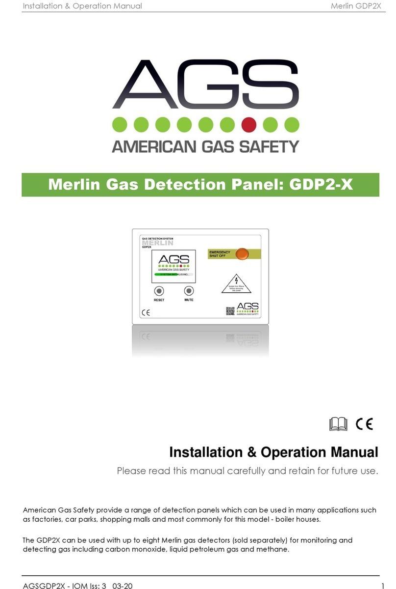
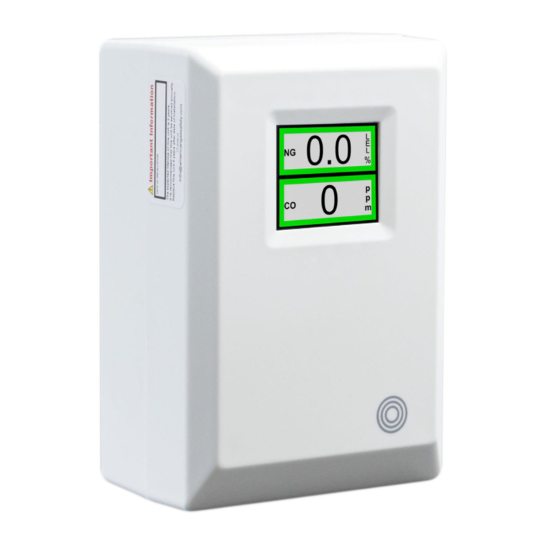
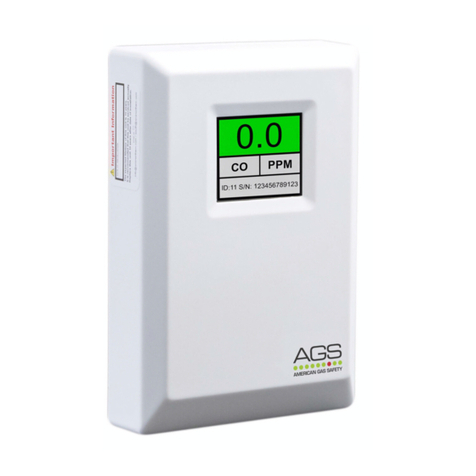
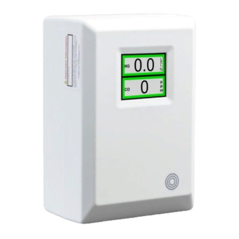
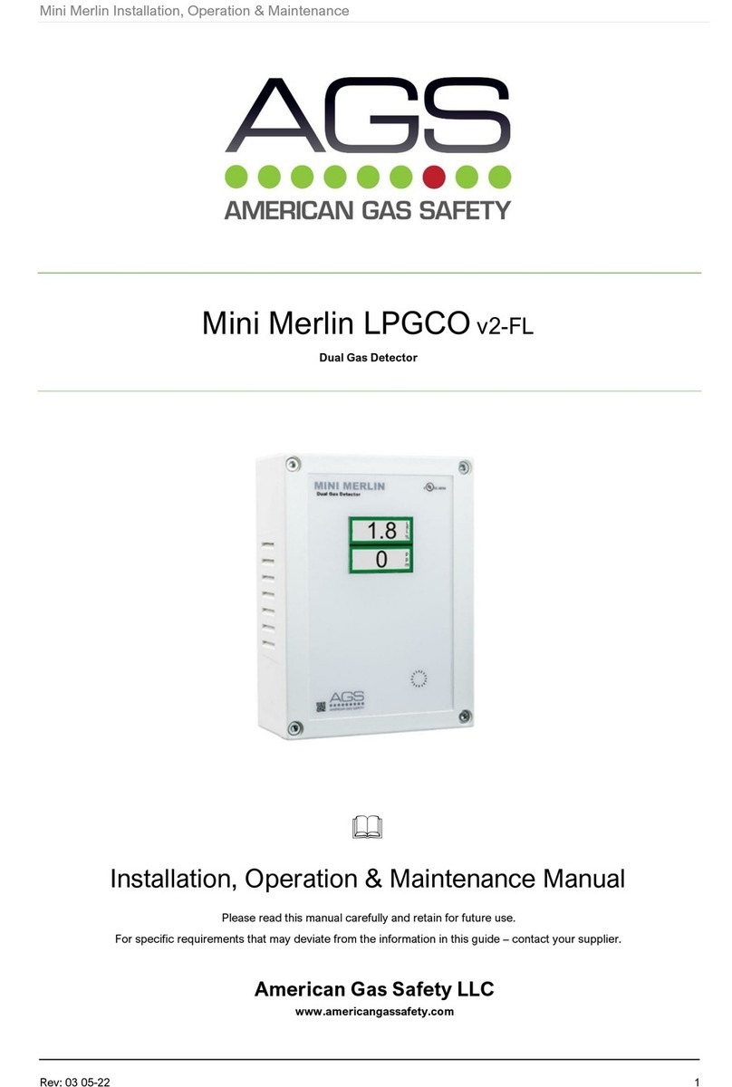
American Gas Safety LLC supply a full range of remote gas detectors that are compatible with
our range of Merlin panels. These consist of carbon monoxide, natural gas, LPG detectors.
2Installation
2.1 Mounting & Position
The control panel is designed for surface mounting using two mounting screws. Removing the
back plate gives access to the circuit board. Do not attempt to remove the PCB.
For the positioning of specific gas detectors please see below:
Natural Gas –12” from the ceiling.
Hydrogen Gas –12” from the ceiling.
LPG –40” from ground level.
Carbon Monoxide –Commercial Kitchens: 67” from ground level.
Commercial Plant Room: 40” from ground level.
2.2 Power Supply
A 12 –24VDC electrical supply should be supplied to the panel and should be connected to
the terminals marked [POWER + -].
2.3 Alarm Relay
Our range of Merlin Gas Detectors can work with various Merlin systems.
If you are using our GDP range you will need to use the [C/L] terminal as an alarm relay
whereas on most other systems gas detectors should be wired to the gas detector terminal on
the Merlin panel using the [N/C] & [COM]. See Wiring Diagram at the end of this document.
xxxTo Avoid Electrical Interference. All low volt connections should be made using a screened cablexxx
3Operation
3.1 Detector ON & OFF
ON - Supply power to the detector
OFF - Remove power to the detector
3.2 LED STATUS
Power - Detector is ON.
Low - When the detector has reached low level alarm –LOW LED will illuminate.
High - When the detector has reached High level alarm state this will illuminate and
the buzzer will sound.
Please see below for further LED information.
