AGS Nitrogen Dioxide Owner's manual

Installation, Operation & Maintenance Parksafe Gas Detector
Rev: 11 0421 1
Parksafe Gas Detector
Nitrogen Dioxide or Carbon Monoxide
Installation, Operation & Maintenance
Please read this manual carefully and retain for future use.
The Parksafe gas detection range designed for installation into car parking facilities and enclosed garages –paired
with the Parksafe control panel, which will monitor up to 16 gas detectors per panel per cable run.
The information contained within this manual should be referenced for typical installation and operation only.
For specific requirements that may deviate from the information in this manual –contact your supplier.

Installation, Operation & Maintenance Parksafe Gas Detector
Rev: 11 0421 2
CONTENT
Important Warning Statements ..............................................................................................3
Installation................................................................................................................................4
Typical Location and Positioning.........................................................................................................4
Access & Mounting ...............................................................................................................................5
Internal Board Overview .......................................................................................................................5
Wiring a Detector...................................................................................................................................6
Wiring a Detector Chain .......................................................................................................................6
Detector ID Switches ............................................................................................................................7
120ohm Termination Resistance .........................................................................................................7
Quick Circuit Test..................................................................................................................................7
Operation .................................................................................................................................8
First Power Up .......................................................................................................................................8
LED Indications ......................................................................................................................................8
Alarm Set Points ....................................................................................................................................8
General Maintenance ..............................................................................................................9
Cleaning..................................................................................................................................................9
Manual Circuit Simulation Test............................................................................................................9
Annual Service Message ......................................................................................................................9
End of Operational Life (EOL)..............................................................................................................9
Bump Test (Gas Response Check) ...................................................................................................10
Specification ..........................................................................................................................11

Installation, Operation & Maintenance Parksafe Gas Detector
Rev: 11 0421 3
Important Warning Statements
Before any installation, use or maintenance read this manual carefully.
The information contained within this manual should be referenced for typical installation and operation only.
For site specific requirements that may deviate from the information in this guide –contact your supplier.
If this device is used in a manner not specified by the manufacturer, the safety and provided by this device may be impaired.
This device is designed for indoor operation only.
The expected lifetime of a NO2 gas sensor element is 2 years upon initial power up. The Parksafe control panel will display a
message to indicate this time and detectors should immediately be replaced.
The expected lifetime of a CO gas sensor element is 5 years upon initial power up. The Parksafe control panel will display a
message to indicate this time and detectors should immediately be replaced.
It is recommended that this device be commissioned upon installation and serviced annually.
Do not apply lighter gas or other aerosols to the device –this will cause extreme damage.
High concentrations of alcohol / ethanol found in many products may damage, deteriorate or affect the gas sensing elements
–Avoid exposure near your device.
This equipment is designed to detect carbon monoxide and nitrogen dioxide from any source of combustion.
It is NOT designed to detect smoke, fire or other gases and should NOT be used as such.
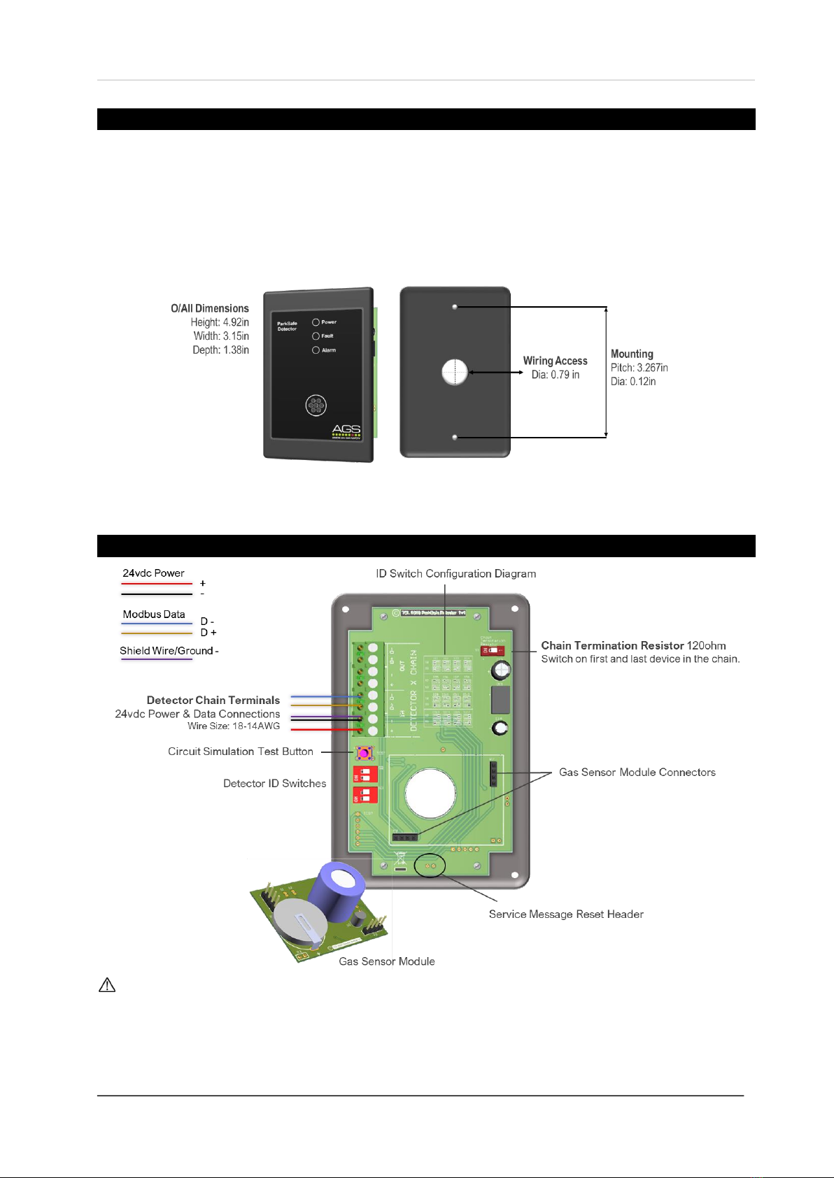
DO NOT remove the gas sensing module when the system is powered up.
This device provides early warning of the presence of nitrogen dioxide or carbon monoxide, usually before a healthy adult
would experience symptoms. This early warning is possible provided your alarm is located, installed and maintained as
described in this guide.
This device requires a continual supply of electrical power –it will not work without power.
This device should not be used to substitute proper installation, use and / or maintenance of fuel burning appliances
including appropriate ventilation and exhaust systems.
This device does not prevent nitrogen dioxide or carbon monoxide from occurring or accumulating.
Actuation of your alarm indicates the presence of dangerous levels of NO2or CO.
Seek fresh air supply and contact your local gas emergency service should you suspect a gas leak.
This device may not fully safeguard individuals with specific medical conditions.
If in doubt, consult a doctor / physician.
Your product should reach you in perfect condition, if you suspect it is damaged, contact your supplier.
Manufacturer’s Warranty
Coverage: The manufacturer warrants to the original consumer purchaser, that this product will be free of defects in material and
workmanship for a period of three (3) years from date of purchase. The manufacturer’s liability hereunder is limited to replacement
of the product with repaired product at the discretion of the manufacture. This warranty is void if the product has been damaged by
accident, unreasonable use, neglect, tampering or other causes not arising from defects in material or workmanship.
This warranty extends to the original consumer purchaser of the product only. Disclaimers: Any implied warranties arising out of
this sale, including but not limited to the implied warranties of description, merchantability and intended operational purpose, are
limited in duration to the above warranty period. In no event shall the manufacturer be liable for loss of use of this product or for any
indirect, special, incidental or consequential damages, or costs, or expenses incurred by the consumer or any other user of this
product, whether due to a breach of contract, negligence, strict liability in tort or otherwise. The manufacturer shall have no liability
for any personal injury, property damage or any special, incidental, contingent or consequential damage of any kind resulting from
gas leakage, fire or explosion. This warranty does not affect your statutory rights. Performance: During the above warranty period,
your product will be replaced with a comparable product if the defective product is returned together with proof of purchase date.
The replacement product will be in warranty for the remainder of the original warranty period or for six months –whichever is the
greatest.
Information on waste disposal for consumers of electrical & electronic equipment.
When this product has reached the end of its life it must be treated as Waste Electrical & Electronics Equipment (WEEE). Any
WEEE marked products must not be mixed with general household waste, but kept separate for the treatment, recovery and
recycling of the materials used. Please contact your supplier or local authority for details of recycling schemes in your area.
At the end of their working life, electrochemical sensors for parksafe detectors should be disposed of in an environmentally safe
manner.Alternatively all detectors can be securely packaged and returned to AGS clearly marked for disposal.
Electrochemical sensors should not be incinerated as this may cause the cell to emit toxic fumes.

Installation, Operation & Maintenance Parksafe Gas Detector
Rev: 11 0421 4
Installation
Typical Location and Positioning
Our detectors should be installed in areas at risk of gas accumulation.
Take in to account the design of the air flow patterns within the parking zone area. Detectors should be installed in the
correct orientation, as recommended by the manufacturer, and ease of access should be accounted for to allow for
any bump tests and other forms of maintenance and identification.
Consider the coverage required and function of the area. Emphasis should be placed on airflow patterns and correct
placement, not perceived detecting ranges. The target gas will only be identified when contact is made with the
sensing element itself.
Locations for Parksafe gas detectors will vary based on the intended application and target gas, they should be
located near where hazardous gas could quickly accumulate and areas of identified consequential risk. The
composition of the target gas and its density relative to air are used as the basis for the recommended height of gas
detectors. These heights may vary based on air flow and temperature conditions in addition to the proposed
application and location.
Carbon Monoxide (CO) gas Breathing Zone - 1700mm (5ft 6”) from ground level.
Nitrogen Dioxide (NO2)gas Low Level - 300mm (1ft) from ground level.
Avoid conditions of any other environmental factors that could potentially impede the accuracy and operation of the
detectors such as; condensation; vibration; temperature, pressure, the presence of other gases, electromagnetic
interference and draft areas.
The gas detectors are designed around a centralised Parksafe control panel of which the location also needs to be
considered. The panel should be located away from the hazardous area that it is monitoring. Accessibility is required
both for status observation and alarm purposes.
The quality of the data signals will vary depending on cable size, number of detectors, the quality and length of the cable
run. Where connections may exceed 500 yards from one control panel. Contact your supplier should issues occur!
The use of sound strobes are highly recommended!

Installation, Operation & Maintenance Parksafe Gas Detector
Rev: 11 0421 5
Access & Mounting
Unpack all the parts! Designed for surface mounting, it must be installed by a licensed, insured contractor.
Carefully remove the front cover of the unit by removing the four screws with a screwdriver. Remove the foam, this is
used for transit purposes only. Using the rear cover - mark the screw holes to the wall. If mounting direct to wall -
ensure the wall surface is flat to prevent base distortion. There is a 0.79” diameter hole for cable entry. Position as per
the recommended heights and in accordance with applicable local/national regulations. After executing the mounting,
connections and ID switches –secure the front cover.
Carbon Monoxide (CO) gas Breathing Zone - 1700mm (5ft 6”) from ground level.
Nitrogen Dioxide (NO2)gas Low Level - 300mm (1ft) from ground level.
Internal Board Overview
Be careful when creating access for cables –Damage to circuit boards will void any warranty!
Any damage attempting to remove the circuit board parts may void any warranty!
Detectors must be earthed/grounded for electrical safety and to limit the effects of EMC or R/F interference!
For MODBUS communications, a shielded cable is used!
Do not remove the Gas Sensor Module when the detector is powered!

Installation, Operation & Maintenance Parksafe Gas Detector
Rev: 11 0421 6
Wiring a Detector
Power and Modbus data are wired between detectors with the first connected
to a control panel DETECTOR CHAIN terminal. If using a shielded wire
(recommended) then connect the shield to [-] power terminals.
For MODBUS communications, a shielded cable is used.
The shielding can be of 2 types: braided [mesh of thin conducting wires]
or foil (consisting of a thin sheet of metal covering the twisted wires).
One example of such cable is BELDEN 3082A.
If you are encountering noise or irregular problems with a Modbus link,
the problem is likely related to grounding, incorrect shielding or wiring mains power next to Modbus wiring.
To ground the data cable, the shield should be connected to [-] of the chain terminals.
Reversing the [D+] and [D-] connections of any device can lead to the whole system to stop working owing to reverse
polarity found on the terminals.
The detector must be earthed/grounded for electrical safety and limit the effects of R/F & EMC interference!
Ensure the 120-ohm termination resistance switch is on at each end of a cable run!
Wiring a Detector Chain
Up to 16 Parksafe detectors can be connected, chained in a parallel ‘daisy chain’ method up to approx. 500 yards
from the panel depending on chain configuration, wire type for power and condition. Any other way may cause issues
or damage to the overall system. It is recommended that the cable of same color should be used to connect all [D+]
terminals together and similarly cable of same color to be used to connect all [D-] terminals together.
Split chain example from a Parksafe Control panel. Single chain example from the Parksafe Control Panel.

Installation, Operation & Maintenance Parksafe Gas Detector
Rev: 11 0421 7
Detector ID Switches
When wiring multiple detectors it is important to identify each detector installed for
the control panel to receive and display accurate data corresponding with the
correct device.
The ID configuration diagram is printed onto detector boards for quick
reference as shown opposite. All detectors are factory set to ID1.
We recommend a plan, map and/or marking the detector enclosures detailing ID and location!
ID Switches must be configured for each detector connected to receive and display accurate data!
120ohm Termination Resistance
Signal communication issues may occur where the bus length is too long, high baud
rates are used or signal reflections are occurring. To avoid this, terminating at each end
of a chain may help the quality of the data signal by turning on the 120-ohm terminal
resistor switch.
If a split chain is used, terminate the last detector in each chain.
If a single chain is used, terminate the first device (Panel) and last device (Detector).
Split chain Single chain
Quick Circuit Test
When the test button on the detector board is pressed and held –the detector will simulate an open circuit to ensure
all configured systems, outputs, alarms, indications and other external devices operate as intended in response to
gas. When the test button is released –the test sequence will terminate and return to normal operation.

Installation, Operation & Maintenance Parksafe Gas Detector
Rev: 11 0421 8
Operation
First Power Up
1. On connecting power, your gas detector Power LED will illuminate.
2. The gas detector then enters a stabilisation phase for approximately 60 seconds –during this time the Fault LED
will flash indicating that the device is not yet ready for operation.
3. The gas detector will then establish a Modbus data signal with the main control panel –during this time the Fault
LED will remain lit.
4. When the data signal has established with the main control panel, the Fault LED will switch off and the detector
will be in operation. Check your Parksafe panel for the gas detector status.
We recommend all gas detection systems be commissioned by a competent/trained engineer to ensure
correct installation and operation!
LED Indications
Power
The Power LED will remain illuminated when power to the detector is present.
Fault
An issue with the gas sensing module, i.e. it has been removed/not installed properly or
The gas sensing module has reached the end of its expected lifecycle or
The gas detector annual service.
Alarm
The system is in alarm condition because dangerous gas levels detected.
Alarm Set Points
▲Rising alarm ▼Falling alarm PPM (Parts per Million)
Gas Detector
Pre-Alarm
Alarm State
Carbon Monoxide (CO)
▲25ppm
▲ 100ppm
Nitrogen Dioxide (NO2)
▲0.7ppm
▲2.0ppm

Installation, Operation & Maintenance Parksafe Gas Detector
Rev: 11 0421 9
General Maintenance
Cleaning
Keep your gas detector in good working order - follow these basic principles;
Remove any dust/debris from the outer enclosure regularly using a slightly damp cloth.
Never use detergents or solvents to clean your device.
Never spray air fresheners, hair spray, paint or other aerosols near the device.
Never paint the device. Paint will seal vents and interfere with the device.
Concentrations of alcohol found in many products may damage, deteriorate or affect the gas sensing elements
such as; wine; deodorants; stain removers and thinners. Other gases and substances to avoid are; corrosives
(i.e. chlorine & hydrogen chloride); alkali metals; basic or acidic compounds; silicones; tetraethyl lead;
halogens and halogenated compounds!
Manual Circuit Simulation Test
When the test button on the circuit board is pressed and held the detector will simulate an open circuit to ensure
configured systems, outputs, alarms, indications and other external devices operate as intended in response to gas.
When the test button is released –the test sequence will terminate and return to normal operation.
Access to the interior of the detector, when carrying out any work, must be conducted by a competent person!
This test does not check the gas sensing element itself!
Annual Service Message
It is recommended that detectors be serviced at least annually from the date of installation for optimum performance
and protection due to sensitivity drifts. A service message will appear on the Parksafe control panel after one year of
detector operation. The detector will still operate during this time but contact your supplier immediately.
The annual service message clock will begin after five (5) hours of continuous power irrespective of whether the system is
then used intermittently. To reset it, the unmarked header on the detector board will need to be shorted out.
End of Operational Life (EOL)
The typical life of a gas detector depends on its application and intended target gas, in addition, the operational life
can be prolonged if the system and equipment is installed and maintained in accordance the instructions stated within
this manual. A message on the Parksafe control panel will indicate that a detector has reached its expected
operational lifecycle. This means the gas-sensing module needs to be replaced and the affected Parksafe detector,
the ‘Fault’ LED will remain illuminated.
The EOL is approximate from the first five (5) hours of continuous power!
The EOL will depend on the type of gas your detector is targeting and may vary depending on its application and
environmental conditions such as the frequency of exposure to the target gas, poisons or inhibitors!

Installation, Operation & Maintenance Parksafe Gas Detector
Rev: 11 0421 10
Bump Test (Gas Response Check)
Gas response checks are often referred to as a ‘bump test’. Bump tests are important to make sure a device is able to
detect a release of gas as early as possible. The aim of the bump test is to make sure a detector is working at its
optimum by briefly exposing the unit to a known concentration of the target gas that usually exceeds the highest
alarm point. If the detector goes into alarm and all signals/outputs activate, then the system is working safely. If the
system fails to operate as intended in an alarm state, the gas detector must not be used until a full inspection and
service has been conducted.
A detector may visually appear in good working order, but its sensitivity can be inhibited by external factors. Dust,
humidity, temperature fluctuations, cleaning products, contaminants or sensor drift (ageing) can cause a decline in
sensitivity and eventual failure. Regular bump tests are important to make sure the detector is able to detect a release
of gas as early as possible and usually takes seconds (gas type dependant i.e. CO sensors will take over a minute). It
is often completed alongside a scheduled fire alarm test; however, the frequency should be determined following an
appropriate risk assessment by the end user. Remember, bump testing does not remove the need to have gas
detectors inspected, calibrated and serviced periodically by a competent person.
Contact your S&S Northern representative for details of suitable bump testing kits and gases. Kits usually consist of a
certified gas cylinder; flow control regulator, tube pipe and applicator cone. We recommend only using S&S Northern
calibration gas kits to ensure correct flow rates meet S&S Northern technical requirements. A bump testing gas is
usually a concentration mix that exceeds the highest alarm set-point.
See below for recommended gas concentrations for bump testing your detector.
Detector Type
Bump Test Gas
Response Time t90
CO - Carbon Monoxide
300ppm (balance in air).
<60s
NO2 –Nitrogen Dioxide
5.0ppm (balance in air)
<60s
All certified test gases supplied by S&S Northern are classified as non-flammable and non-toxic, however, they do
contain gas under pressure and may explode if heated to extreme temperatures and cause asphyxiation in high
concentrations.
Procedure
IF YOU ARE TESTING THE ACTUATION OF OUTPUTS / RELAYS, PROCEED TO STEP 2.
STEP 1.
•Access service mode by pressing the AGS logo on the control panel main screen only. The screen will display a
service prompt. Press Yes. (Note: All alarm signals/outputs will be inhibited for fifteen (15) minutes.
•Proceed to test detector(s). Upon completion –exit service mode by pressing the ‘Exit’ button on screen. If you
need more time, exit and re-enable service mode. The system returns to a normal state after fifteen (15) minutes
automatically if the ‘exit’ button is not pressed.
When service mode is enabled, the control panel will ignore all alarm signals/outputs!
The panel will return to a normal operational state after fifteen minutes automatically unless service mode is disabled
manually by pressing the [EXIT] button on screen!

Installation, Operation & Maintenance Parksafe Gas Detector
Rev: 11 0421 11
STEP 2.
•Ensure you have the correct gas for the device type prior to application.
•Screw the regulator/valve into the gas cylinder outlet.
•Once sealed, the regulator pressure gauge (if available) will indicate cylinder pressure.
•Offer up the applicator hose/cone and fully cover the sensing element on the front case.
•Open the valve/regulator to allow the gas to be delivered at a pre-set flow rate.
•Apply gas.
•The detector Alarm LED will illuminate at the alarm set point.
•Remove applicator hose/ cone and turn the gas cylinder regulator/valve off.
•Wait for detector to stabilise / return to normal.
•Reset the service reminder by shorting out the unmarked header.
•Test complete.
Always remove the regulator/valve after use - All cylinders will re-seal upon removal of the regulator!
Never use expired or ‘near empty’ gas cylinders!
Always give at least five (5) minutes between testing the same unit or until gas has fully dispersed!
Always consider safety and use equipment in accordance with Safety Data Sheets!
Specification
General
Product:
Park Safe Detector
Model(s):
CO (Carbon Monoxide) NO2(Nitrogen Dioxide)
Use:
Indoor, Car Parks, Garages Non-Hazardous Areas (not to be used in potentially explosive atmospheres)
Indicators (LED)
Green (Power), Yellow (Fault State) & Red (Alarm).
Orientation
Wall Mounted
Electrical
Max. Power Consumption
15mA Max @ 24Vdc
Power Voltage Input Range
12-32Vdc (24vdc Nominal)
Communication
RS485, Modbus RTU
Terminal Wire ratings
Copper 18AWG (0.75mm2) Min.
8x screw terminals.
End of Life/ Service Battery
CR2032 - 3V 220mA Radial Lithium Annual service reminder activated upon five (5) hours of continuous
power. EOL activated upon five (5) hours of continuous power.
Max Chain Length
500 Yards approx
Construction
Dimensions (H x W x D)
4.92 x 3.15 x 1.38”
Unit Weight (Approx.)
1.6oz
Nominal Orientation
Wall Mounted (No Limits)
Housing Material
General purpose ABS plastic
Environmental
Ingress Protection
IP43
Storage Conditions
Dry. Temp: -4 ~ 122°F RH: 15 ~ 90%
Sensor Operating Temperature
-4 ~ 122°F
Sensor Operating Humidity
Continuous 30-80% RH Non-Condensing
Sensor Operating Pressure
Normal Atmospheric Pressure ± 10%
Compliance
CE
BS EN 50270 / BS EN 61010-1
Sensor Specification & Performance
Factory Calibration Conditions
25° ± 5°C - 77° ± 41°F (40-70% RH)
Sensor Type
Electromechanical
Gas Sensor
Measuring
Range (ppm)
Calibration Gas
Response (T90)
Recovery (T10)
Alarm: 1
(Pre alarm warning)
Alarm: 2
*EOL
(Years)
Carbon
Monoxide (CO)
0-10,000
120ppm CO
<60s
<50s
▲25ppm
▲100ppm
5
Nitrogen Dioxide
(NO2)
0-20
5ppm NO2
<60s
<50s
▲0.7ppm
▲2ppm
3
▲Rising Alarm ▼Falling alarm *EOL –Expected operational Life –Replace unit after this time.

Installation, Operation & Maintenance Parksafe Gas Detector
Rev: 11 0421 12
Installation Details
Please pass this manual to the system owner / user.
Date of Installation:
Installation Location:
Organisation:
Stamp/Signature of the installer:
We recommend all AGS gas detection equipment be commissioned by competent/trained engineers to ensure correct
installation and operation. The Merlin range of gas detectors are calibrated when manufactured, however, we strongly
recommend the detectors response and alarm signals are tested and validated once installed. This will ensure the
equipment performs as intended and is free from any unforeseen damage caused by transit/installation.
Every effort is made to ensure the accuracy of this document; however, AGS can assume no responsibility for any errors or
omissions in this document or their consequences. AGS would greatly appreciate being informed of any errors or omissions
that may be found in the content of this document. For information not covered in this document, or if there is a requirement
to send comments/corrections, please contact AGS using the contact details given below.
American Gas Safety LLC
Head office:
6304 Benjamin Road, Suite 502, Tampa, FL 33634
Tel: (727) 608-4375
American Gas Safety LLC is the owner of this document and reserves all rights of modification without prior notice.
This manual suits for next models
1
Table of contents
Other AGS Gas Detector manuals

AGS
AGS Mini Merlin LPGCO v2 TX Instruction manual

AGS
AGS Mini Merlin User manual

AGS
AGS Mini Merlin LPGCO User manual

AGS
AGS Mini Merlin Owner's manual

AGS
AGS Merlin 1000S+ Owner's manual

AGS
AGS Merlin GDP4 User manual

AGS
AGS PARKSAFE GAS DETECTOR Owner's manual

AGS
AGS Merlin GDP2X User manual

AGS
AGS Merlin Installation instructions

AGS
AGS Merlin Guide