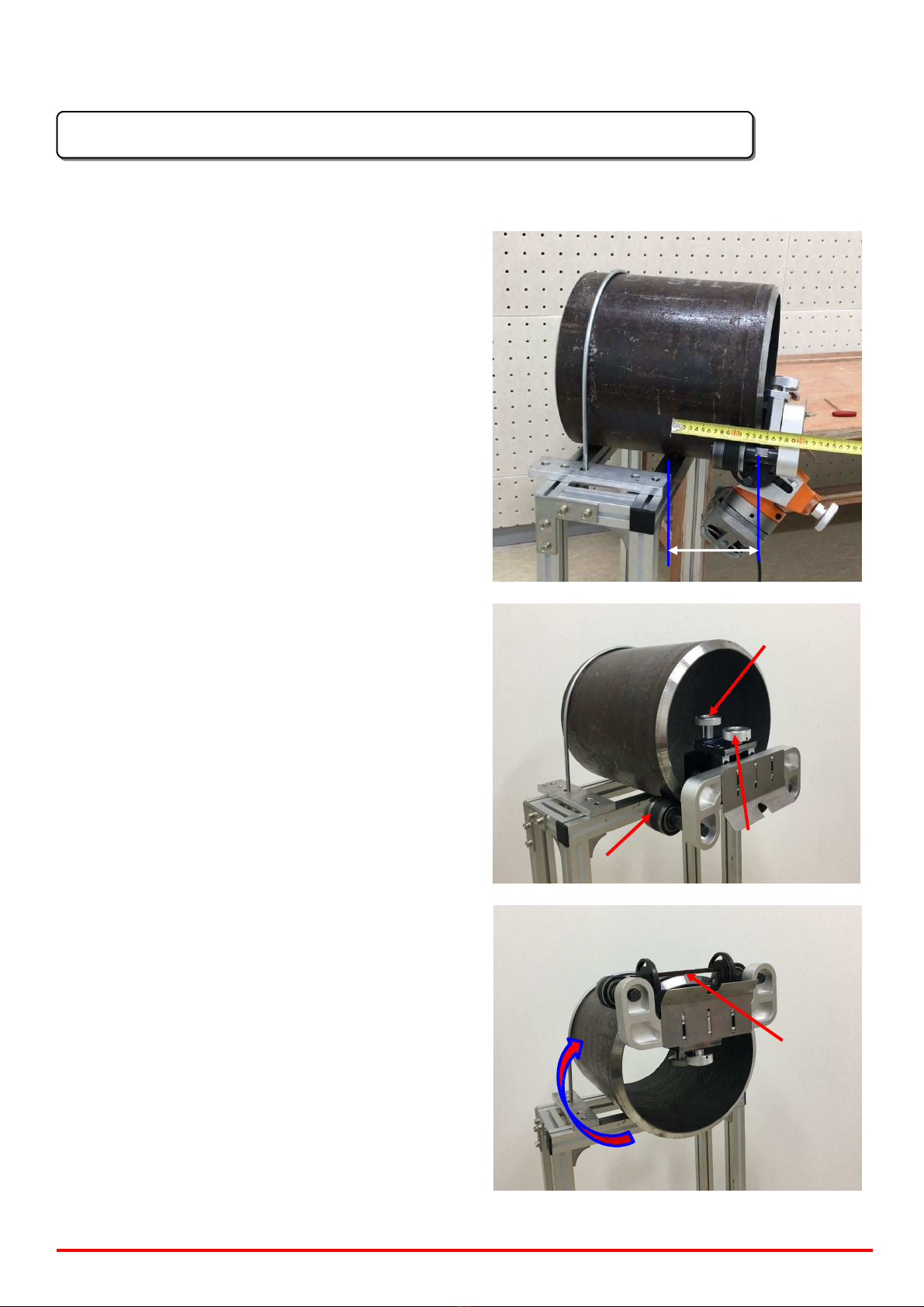
5. Turn the machine installed from the bottom
of the pipe clockwise so that it could be
positioned on the top of the pipe. (This
machine should be turned in clockwise
direction only. Never turn it anticlockwise.)
6. Turn the Chamfering Value Adjustment
Handle (Chamfer-Mill List No. 16) of the
Chamfer-Mill and set the beveling value to
be below zero (0) level. After that, install the
machine between the End Caps (List No. 7)
on both sides and match the angle. Tighten
4 units of M8x20 hexagonal bolts (Chamfer-
Mill List No. 27). (At this time, if the
beveling value is not set at under zero (0)
level, it may cause damages on the machine
and installation could be difficult.)
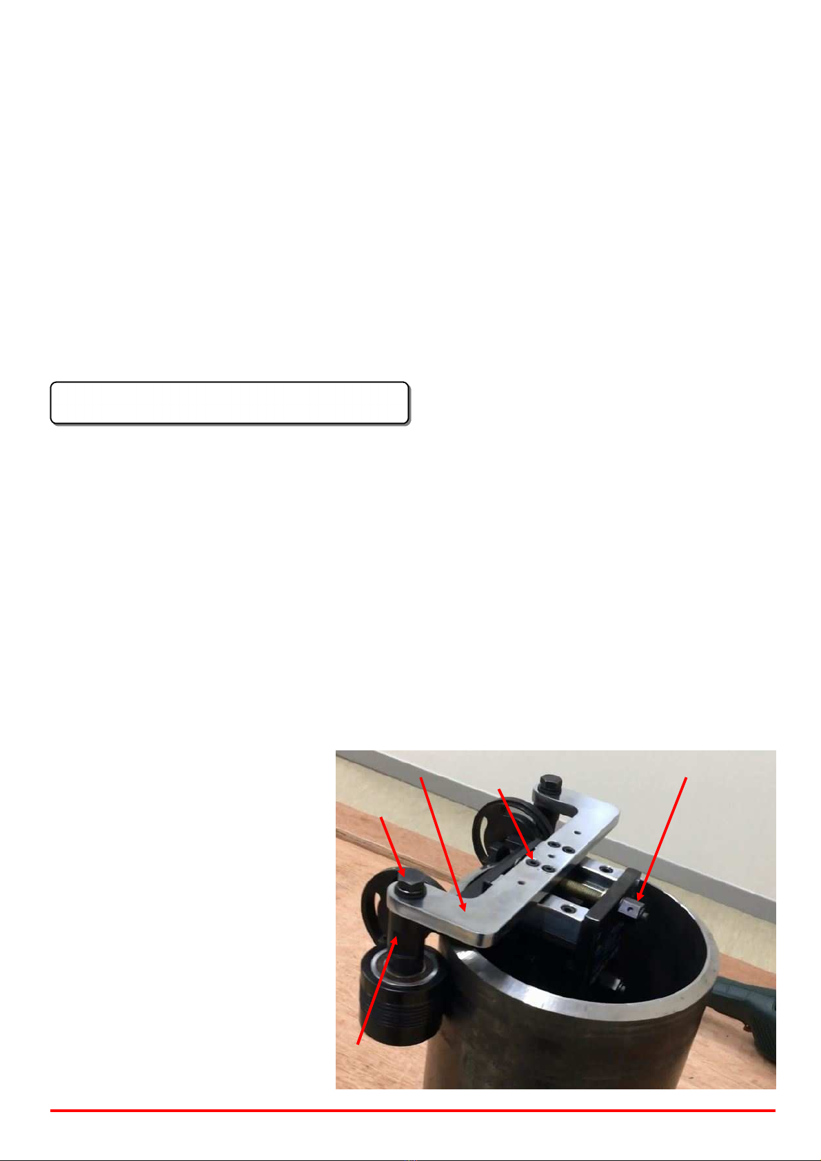
7. Insert the two Operational Handles (List No.
19) on both sides to the Outer Roller Shaft.
(List No. 16)
8. When inserting the left-hand side
Operational Handle, if it is difficult to insert
the Handle because the position of the
motor is not appropriate, loosen the Locking
Bolt (Chamfer-Mill List No. 13), adjust the
position of the Handle and then tighten the
Locking Bolt again.
End
cap
No.13 Locking
bolt
Operational Handles
9. After wearing the protective kit, turn on the switch of the motor first and then adjust the
intended beveling value by turning the Beveling Value Adjustment Handle (Chamfer-Mill
List No. 16) (Actual beveling work is started from this point on at a standstill state). Start
the beveling work by turning the Operational Handles clockwise with your hands.
10. The speed of the rotation should be different according to the beveling quantity, materials
and state of the insert tips. Therefore, the workers should adjust the speed of the rotation
appropriately.
11. After the beveling work is finished, turn off the switch of the motor and set the beveling
value at below zero (0) level for safety and beveling work next time.
MP0020-26 User’s Manual - 6 - AHA Industrial Co / www.ahaind.com