Harken LokHead 500 User manual

Please read these instructions carefully before operating equipment.
Winch LokHead 500
INLH500
Instruction Manual
Original Instructions
Rev. 02
ULH500_04/04/2016


3
ENGLISH04-04-16
Index
Index..................................................................................................................................... 3
Introduction .......................................................................................................................... 5
About This Manual ����������������������������������������������������������������������������������������������������������������������������5
Glossary and Symbols�����������������������������������������������������������������������������������������������������������������������5
General Information.............................................................................................................. 6
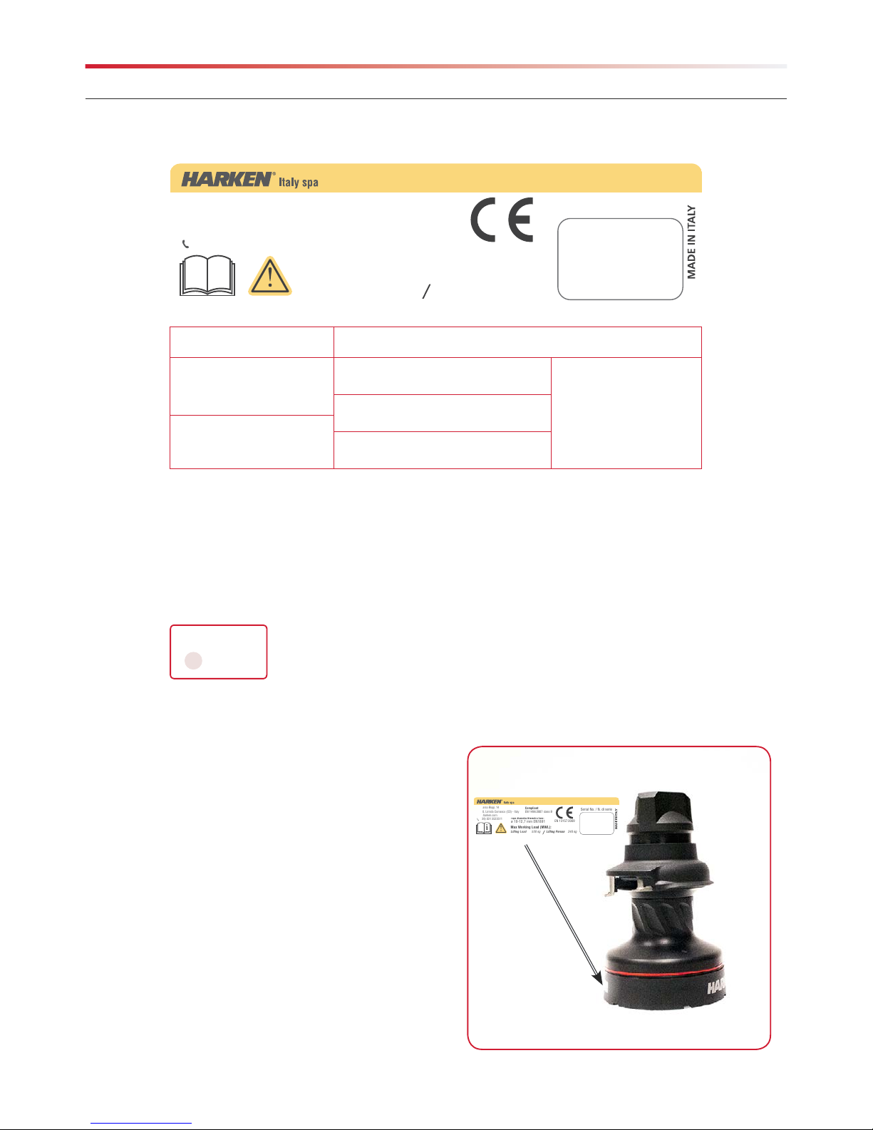
Identification Data and Plates on the Device �������������������������������������������������������������������������������������6
Model for Declaration of EC Compliance ������������������������������������������������������������������������������������������7
Technical Support Information�����������������������������������������������������������������������������������������������������������8
General Advice�����������������������������������������������������������������������������������������������������������������������������������8
Intended Use��������������������������������������������������������������������������������������������������������������������������������������8
Improper Use �������������������������������������������������������������������������������������������������������������������������������������8
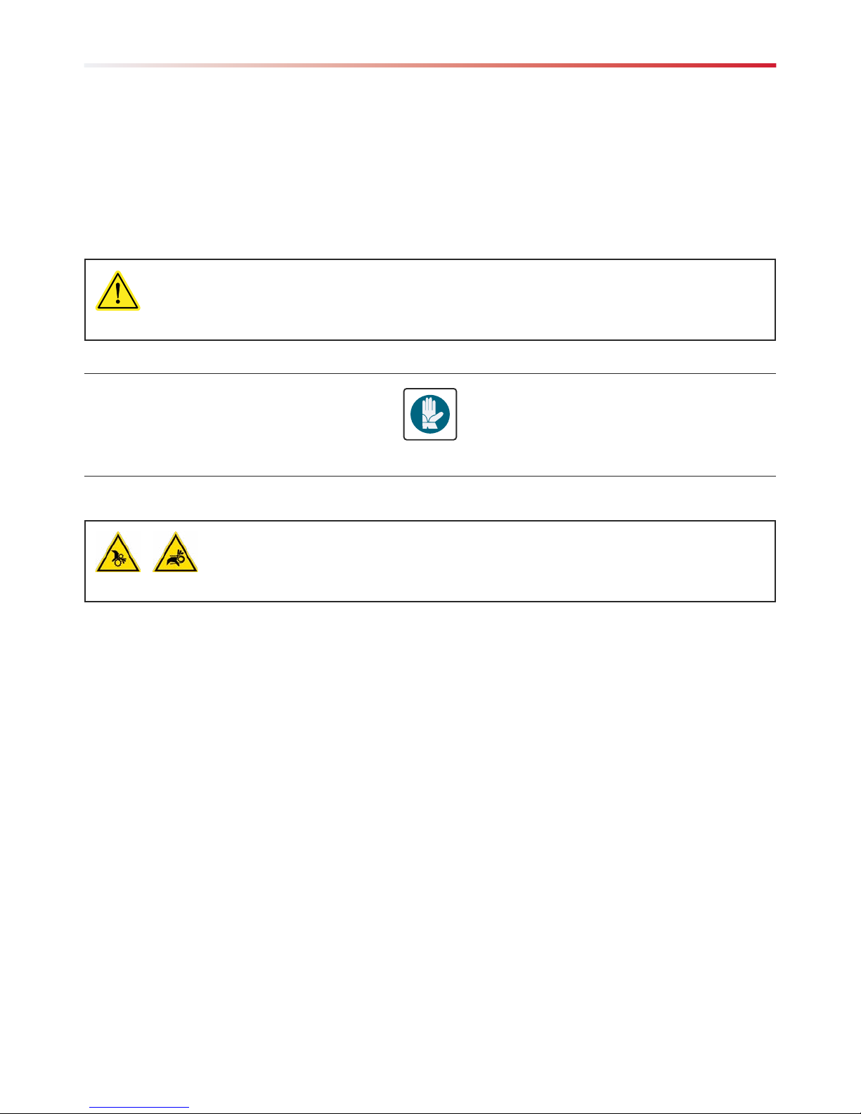
Personal Protective Equipment (PPE)������������������������������������������������������������������������������������������������9
Residual Risks �����������������������������������������������������������������������������������������������������������������������������������9
Safety Information................................................................................................................ 9
Winch LokHead 500 ........................................................................................................... 10
System Description��������������������������������������������������������������������������������������������������������������������������10
Standard Configuration.............................................................................................................................10
Tripod Use Configuration..........................................................................................................................10
Outline ���������������������������������������������������������������������������������������������������������������������������������������������11
Standard Configuration............................................................................................................................. 11
Tripod Use Configuration..........................................................................................................................12
Max Working Load ��������������������������������������������������������������������������������������������������������������������������13
Rope Requirements��������������������������������������������������������������������������������������������������������������������������13
Technical Data ���������������������������������������������������������������������������������������������������������������������������������13
Lokhead Winch Installation��������������������������������������������������������������������������������������������������������������14
Mounting Surface ..................................................................................................................................... 14
Winch Entry Angle of Lifting Rope ............................................................................................................ 14
Winch Location ......................................................................................................................................... 14
Installation Procedure ............................................................................................................................... 14
Final Installation........................................................................................................................................16
Mounting Template - Lokhead Winch....................................................................................................... 17
Mounting Template - Plate Adapter .......................................................................................................... 17
Lokhead Winch, Plate and Plate Adapter Installation ����������������������������������������������������������������������18
Positing the control lever ..........................................................................................................................18
Lokhead Winch, Plate and Tripod Adapter Installation ��������������������������������������������������������������������20
Using The Device - Checking The Device Before Use���������������������������������������������������������������������23
Using The Device - Checking The Device Before Use............................................................................... 24
Lifting Load��������������������������������������������������������������������������������������������������������������������������������������24
Lowering Load ���������������������������������������������������������������������������������������������������������������������������������27
Maintenance ������������������������������������������������������������������������������������������������������������������������������������27
Wash......................................................................................................................................................... 27
Maintenance Schedule ............................................................................................................................. 27
Spare Parts................................................................................................................................................28
Handling ������������������������������������������������������������������������������������������������������������������������������������������28
Storage���������������������������������������������������������������������������������������������������������������������������������������������28
Maintenance Schedule���������������������������������������������������������������������������������������������������������������������28
Worldwide Limited Warranty.............................................................................................. 32

4
ENGLISH 04-04-16

5
ENGLISH04-04-16
ABOUT THIS MANUAL
This User Manual is an integral part of the device and aims to provide all the information needed for its safe and correct use
and for proper maintenance�
If there are instructions you do not understand, contact Harken�
Keep the manual in a safe place for future consultation� This manual may be modified without notice� Updated versions are
available on www�harkenindustrial�com�
This manual is for qualified operators (refer to the Safety Information chapter for more information)� Improper use of the device
or incorrect maintenance could cause severe damage or death�
Harken accepts no responsibility for damage, personal injury or death caused by failure to observe the safety information and
instructions in this Manual�
The manufacturer cannot be liable for damage, injury or consequential loss resulting from installation or servicing by unqualified
personnel�
The manufacturer will also not be liable for damage, injury, or consequential loss resulting from incorrect operation or
modification of the equipment�
GLOSSARY AND SYMBOLS
Intended Use - use of the device according to the information supplied in the instructions for use�
Improper Use - use of the device in a way different from that indicated in the instructions for use�
Qualified Operator - people who have attended specialisation, training, courses, etc� and are qualified for using lifting people
devices to the current regulations of the Nation in which the device is used for rescue�
General User - a user that use the device to lifting loads
Text preceded by the following symbols contains very important information or instructions, especially in regards to safety�
Failure to observe these may lead to:
- danger for operators
- invalidity of the contract warranty
- refusal of the manufacturer to accept responsability
Introduction
WARNING!
this denotes the existence of the potential danger, which could cause injury or damage if the
information or instructions are not followed
NOTE!
this denotes important information concerning the device

6
ENGLISH 04-04-16
General Information
IDENTIFICATION DATA AND PLATES ON THE DEVICE
Each device is identified by a CE plate on which the reference data of the device are inscribed indelibly� Always quote these
references when contacting the manufacturer or service centres�
1� name of manufacturer
2�name of product and model
3�manufacturer's identification data
4�CE mark according to 2006/42/CE
5�
serial number in format:
last two numbers of the year of manufacture of the device (e�g� 15 = the year 2015)
6�pictogram instructing you to read the manual before using the
device
7� safety information on the diameter of the rope to use:
minimum 10 mm, maximum 12,7 mm: this rope must be EN
1891 certified
8�indicator of the Max Working Load (MWL) of the device, with
specific load for lifting load and lifting person
The CE plate is on the skirt of the device (see figure on right)
i
INLH500
Serial No. / N. di serie
Compliant:
EN 1496:2007 class B
EN 13157:2009
via Marco Biagi, 14
22070, Limido Comasco (CO) - Italy
www.harken.com
(+39) 031 3523511
Winch LokHead 500
rope diameter/diametro fune:
ø 10-12,7 mm EN1891
Max Working Load(MWL):
Lifting Load
500 kg
Lifting Person
240 kg
1
3
5
6
2
4
7
8
S XXXXX
XXXXXXXXX
i
INLH500
Serial No. / N. di serie
Compliant:
EN 1496:2007 class B
EN 13157:2009
via Marco Biagi, 14
22070, Limido Comasco (CO) - Italy
www.harken.com
(+39) 031 3523511
Winch LokHead 500
rope diameter/diametro fune:
ø 10-12,7 mm EN1891
Max Working Load(MWL):
Lifting Load
500 kg
Lifting Person
240 kg

7
ENGLISH04-04-16
General Information
MODEL FOR DECLARATION OF EC COMPLIANCE
to carry out the technical file for it
Name and Surname: Andrea Merello
Address: HARKEN ITALY S.p.A. Via Marco Biagi, 14 Post code: 22070 Province: Como
City: Limido Comasco Country: Italy
complies with the essential requirements defined by the following directives:
Directive 2006/42/CE of the European Parliament and Council of 17th May 2006 concerning "machines" amending
directive 95/16/CE;
Regulations reference: EN 13157:2009
Technical standards used: EN 1496:2007 Class B
and authorises
DECLARATION OF EC COMPLIANCE
1. (All. IIA Dir. 2006/42/CE)
The undersigned
Harken Italy S�p�A�
Via Marco Biagi, 14, 22070 Limido Comasco (CO) Italy
Telephone: +39 031/3523511, Fax: +39 031/3520031
Email: italy@harken�it, Web: www�harken�it
hereby declares
that the hand powered crane:
Winch Lokhead 500
Model
INLH500
Serial Nr�
HARKEN ITALY S.p.A.
Legal representative

8
ENGLISH 04-04-16
TECHNICAL SUPPORT INFORMATION
LokHead Winch is covered by a warranty, as laid down in the general conditions of sale� If during the warranty period the device
proves defective or suffers breakages, as indicated in the warranty, the manufacturer, after checking the device, will repair or
replace the defective components� You are reminded that modifications carried out by the user, without explicit written
authorisation from the manufacturer, will invalidate the warranty and relieve the manufacturer of any responsibility for damage
caused by the defective product� The same considerations apply when spare parts that are not original or different from those
explicitly indicated by the manufacturer� For all these reasons we advise customers to contact Harken Technical Support�
General Information
Safety Information
GENERAL ADVICE
Use of the LokHead Winch for lifting people, in rescue situation, is restricted to qualified operators who have attended specialist,
training, courses, etc� and are qualified for using rescue lifiting devices to the current regulations of the Nation in which the
device is used for rescue�
Use of the LokHead Winch for lifting loads is permitted to a general user in accordance with National Regulations & Working
Guidelines/Practices�
Harken is not responsible for damage caused by the LokHead Winch to people, animals or property in the case of:
- use of the LokHead Winch by operators not qualified operators for liting people
- improper use of the LokHead Winch
- lack of proper maintenance, as indicated in the Maintenance chapter of this Manual
- unauthorised modifications or changes
- use of spare parts that are not original or specific for the model
- total or partial failure to observe the instructions
- usage contrary to specific national regulations
INTENDED USE
This winch is designed to be used as a manually powered, rope-handling winch for lifting, lowering, and pulling loads�
Moreover the LokHead Winch is designed and compliant to be used in rescue operation, by a qualified operator�
The LokHead Winch must be used after being mounted on a suitable anchorage point�
It is designed to be mounted with the base in a vertical plane�
All the equipment and anchor devices used in conjunction with the Lokhead winch to lift person in rescue operation , must be
certified for their intended use in the rescue operation�
IMPROPER USE
The winch must not be used:
- for purposes different from those outlined in “Intended use” chapter, or for purposes not mentioned in this manual or
different from those mentioned
WARNING!
read the instructions in this manual attentively and carefully follow the indications it contains
before using the LokHead Winch.

9
ENGLISH04-04-16
Safety Information
PERSONAL PROTECTIVE EQUIPMENT (PPE)
It is necessary use gloves when operating the device�
RESIDUAL RISKS
You must pay attention to the following residual risks present when using LokHead Winch:
- if unauthorised modifications or interventions have been carried out
- in an explosive atmosphere
- after it has fallen from a height of more than 1 meter onto a hard surface� In this case the device must be returned to the
manufacturer or to a Harken authorised repair centre
- with wire rope
- with loads in excess of the Maximum Working Load (MWL) of 240 kg for lifting persons in rescue operation
- with loads in excess of the Maximum Working Load (MWL) of 500 kg for lifting loads
WARNING!
Subjecting the winch to loads above the maximum working load can cause the winch to fail or pull
off the mounting surface suddenly, possibly resulting in severe injury or death.
WARNING! Rotating Parts Trapping Risk
Always wear clothing and protective gloves that are form fitting. Avoid loose gloves or
clothing and always follow the instructions in the manual.

10
ENGLISH 04-04-16
Winch LokHead 500
Pos. Description
1Knob
2Stripper Arm
3Drum
4Removable Skirt
5Handle Socket
6Handle Lock
7Winch Handle
SYSTEM DESCRIPTION
Standard Configuration
Tripod Use Configuration
Pos. Description
1Control Lever
2Winch Lokhead 500
3Plate
4Tripod Adapter
5Anchor Device
6Connector
7Winch Handle
2
3
45
6
7
1
1
5
2 3 4
6 7

11
ENGLISH04-04-16
Winch LokHead 500
OUTLINE
Standard Configuration
56 255
Ø157
292
11864
25
56 255
Ø157
292
11864
25

12
ENGLISH 04-04-16
Winch LokHead 500
Tripod Use Configuration
742
573
143
889
254

13
ENGLISH04-04-16
Winch LokHead 500
MAX WORKING LOAD
The Max Working Load of the Winch LokHead 500 is:
- 500 kg (1102,31 lb) for lifting loads
- 240 kg (529,11 lb) for lifting person in rescue operation
ROPE REQUIREMENTS
TECHNICAL DATA
Rope Semi static 10mm-12�7mm (1/8"-½") EN1891 rope for lifting
person in rescue operation�
10mm-12�7mm rope for lifting loads
Max Working Load 500 kg (1102,31 lb) - lifting loads
240 kg (529,11 lb) - lifting person in rescue operation
Power Ratio 13,50:1 - 1st speed / 39,90:1 - 2nd speed
Gear Ratio 2,13:1 - 1st speed / 6,28:1 - 2nd speed
Winch Weight 4,2 kg (9,25 lb)
Winch Handle Weight 0,5 kg (1,10 lb)
Plate + Plate Adapter Weight 2,8 kg (6,17 lb)
Tripod Adapter 2,2 kg (4,85 lb)
Winch Dimensions 311 x Ø157 mm (12,24" x Ø6,18")
Recommended working temperature range -20°C +50°C
WARNING!
Do not apply a load greater than the Max Working Load to the Winch LokHead.
WARNING!
Use only EN1891 certified ropes with a diameter of between 10 - 12.7 mm (3/8" - 1/2") for lifting
person.
WARNING!
Use only ropes in good condition.
WARNING!
For correct maintenance of ropes consult the rope Usage Manual.
WARNING!
Do not use with wire rope.

14
ENGLISH 04-04-16
Mount winch so drive gear (11 - Pinion Z13) is positioned where rope enters winch drum�
Note: on winch skirt identifies location of drive gear�
Winch Location
Winch must be installed in a position to allow sufficient working space around unit, so not to
impede operation of handles�
Winch must be installed in a position to ensure visibility of the lift trajectory by operator at all times�
Harken®accepts no responsibility for defective installation or reassembly of its winches� If you have questions or concerns,
Harken® Tech Service is at your disposal at techservice@harken�it�
Installation Procedure
To install the winch you have to purchase separately five (5) M6 Hex Head (HH) Bolts (Galvanized, 10�9 UNI EN ISO 4014:2003)
Harken®does not supply bolts to install winch since lengths may vary depending on mounting surface�
It is installer's responsibility to choose correct bolts, taking into account loads they will have to withstand�
Harken®assumes no responsibility for incorrect installation of winch or for use of incorrect mounting bolts�
LOKHEAD WINCH INSTALLATION
Mounting Surface
Winch must be installed on a flat surface, reinforced if necessary, to withstand a load equal of 2400 kg�
Winch Entry Angle of Lifting Rope
Winch entry angle must be 8° with a tolerance of ±2° to avoid rope overrides�
Winch LokHead 500
WARNING!
Mount winch so that drive gear is positioned where rope enters winch
drum. Incorrect positioning of drive gear can weaken winch leading to
failure, possibly resulting in severe injury or death.
WARNING!
Incorrect installation of winch may cause severe injury or death. Consult equipment supplier if in
doubt about correct position of winch.
WARNING!
Failure to use correct number and type of mounting fasteners or failure to ensure correct mounting
surface strength can result in winch pulling off suddenly and unexpectedly during high loads,
possibly resulting in severe injury or death.
WARNING!
Verify entry angle of rope. It must be 8° with tolerance of ±2°, to avoid
rope overrides and damaging winch or making winch inoperable,
leading to loss of control, possibly resulting in severe injury or death. drive gear
SHEET
NOTE!
1/4" Hex Head bolts do not fit in the holes and cannot be used to mount winch.
8°

15
ENGLISH04-04-16
To install the winch you must remove the winch skirt and use five (5) M6 Hex Head (HH) Bolts (Galvanized, 10�9 UNI EN ISO 4014:2003)�
Tools needed: One medium flat-bladed screwdriver
Winch LokHead 500
Note: ¼" Hex Head bolts will not work for this procedure� 3� Reposition the skirt in housing and press down it to position
correctly�
Note: Make sure skirt is correctly clipped on to base of winch�
1� Remove the skirt with the help of the screwdriver placed as
shown by the symbol
2� Take off the skirt and position the 5 M6 hexagonal headed bolts
in their holes

16
ENGLISH 04-04-16
Winch LokHead 500
Final Installation
1� Carry out Installation Procedure, then install winch on a flat surface in selected position�
2�Position base of winch in selected area and mark holes or use drilling template�
Drilling template is available on Harken®website, www�harken�com� Download, print and compare template to winch to
verify that size of template and hole position/sizes are correct� See reduced-size template�
3�Remove winch and drill five (5) 6�2 mm diameter clearance holes� If drilling and tapping consult industry standards for
drill/tap size� Important: Do not countersink bolts�
4�Bolt base of winch to support plate� Use bolts that are the correct length for thickness and type of support plate� Consult
equipment supplier if in doubt� Use five (5) M6 Hex Head (HH) bolts, washers, and nuts�
5�To obtain correct Maximum Working Load (MWL) all five bolts, nuts, and washers must be securely tightened�
Install the handle socket as shown:
NOTE!
When downloading winch templates make sure you have correct size paper and that printer will
output at 100%. Before drilling holes verify that template is correct in every detail. Harken cannot
be responsible for incorrectly drilled holes because of a faulty template.
NOTE!
1/4" Hex Head bolts do not fit in the holes and cannot be used to mount winch.
4� Position the handle socket on the shaft� 5� Tighten the handle socket screw.
WARNING!
Failure to use correct number and length of mounting fasteners and/or failure to tighten them
correctly can result in winch pulling off suddenly and unexpectedly during high loads which may
cause load to drop, possibly resulting in severe injury or death.

17
ENGLISH04-04-16
Winch LokHead 500
Mounting Template - Lokhead Winch
Mounting Template - Plate Adapter
Drilling template of the holes provided for fastening with M12 screws
Ø13
49 102 49
78
11
11
35°
105°
50°
70°
50°
50°
Ø123
n°5 holes - Ø6
Ø80 - cut out
final pinion position
winch outside Ø157

18
ENGLISH 04-04-16
Winch LokHead 500
LOKHEAD WINCH, PLATE AND PLATE ADAPTER INSTALLATION
Positing the control lever
Install the LokHead winch and plate adapter fixing the plate with four(4) M12 bolts, washers and nuts on a flat surface, which
whithstand a load equal of 2400 kg�
It is installer's responsibility to choose correct bolts, taking into account loads they will have to withstand�
Harken assumes no responsibility to incorrect installation of winch and plate adapter or for use of incorrect mounting bolts�
3� Tighten the control lever screw� Install the winch on the plate following the procedure described in
the Lokhead Winch Installation chapter� Fix surely the plate to the
plate adapter with the self-locking nut�
1� Untighten the knob screw� 2� Position the control level using the screw supplied with
transformation kit�

19
ENGLISH04-04-16
Only for lifting loads:
- It is possible to fix the plate using ratchet strap,
connectors, anchor devices�
- It is the installer's responsibility to carry out all
structural tests needed to ensure that the mounting
surface can withstand the load�
Ensure the plate is securely attached to the mounting surface,
so that it can operate under load without significant movement�
The winch plate must be installed so that the line can be led
through the pigtail to the winch drum, with no more than 30°
of line deflection in any plane� The installation should use
pulley deflectors if necessary to ensure a fair lead to the
winch� The pigtail should not take any angle load�
Winch LokHead 500
The winch plate must be installed in a position to allow sufficient working space around unit, so not to impede operation of
handles�
Winch plate must be installed in a position to ensure visibility of the lift trajectory by operator at all times�
WARNING!
Failure to use correct number and type of mounting fasteners or failure to ensure correct mounting
surface strength can result in winch pulling off suddenly and unexpectedly during high loads,
possibly resulting in severe injury or death.
WARNING!
Incorrect installation of winch plate may cause severe injury or death. Consult equipment supplier
if in doubt about correct position of winch plate.
max. deflection
30°
max. deflection
30°
Fixing with M12 bolts to the load Fixing with Ratchet Strap
Only for lifitng loads to the load
to the anchorage point

20
ENGLISH 04-04-16
LOKHEAD WINCH, PLATE AND TRIPOD ADAPTER INSTALLATION
Winch LokHead 500
WARNING!
Before installing the plate on the leg tripod check the dimensional compatibility between them.
D
A
0
51
51
100
100
0
39
50
39
50
A
Clamping wing-nut
Clamping plate
PARALLEL
see note below
Drilling template of the holes provided for fastening with M12 screws
Adapter plate
Round section diameter range: Ø40-Ø65 mm
NOTE: Set the adjusting nut according to "B" dimension to mantain parallelism between plates in clamping position (clamping wing-nut tightened)
A B
35 35 40 45 50 55 60 65
40 40 45 50 55 60 65
45 45 50 55 60 65
50 50 55 60
55 55 60
60 60
This manual suits for next models
1
Table of contents
Other Harken Power Tools manuals