PR 5331A User manual
5331
2-Wire Programmable
Transmitter
No.5331V114-UK
From ser. no. 141365001

1510
Revision Notes
The following list provides notes concerning revisions of this document.
Rev. ID Date Notes
113 13/45 IECEx and INMETRO approvals added
114 15/10 PESO/CCOE approval added
GOST approval replaced with
EAC approval

5331V114-UK 1
2-WIRE
PROGRAMMABLE TRANSMITTER
5331
CONTENTS
Application................................................................................................. 2
Technical characteristics...................................................................... 2
Mounting / installation ......................................................................... 2
Applications............................................................................................... 3
Order: 5331............................................................................................... 4
Electrical specifications........................................................................ 4
Connections .............................................................................................. 8
Block diagram........................................................................................... 9
Programming ............................................................................................ 10
Mechanical specifications ................................................................... 11
Mounting of sensor wires ................................................................... 11
Appendix .................................................................................................... 12
ATEX Installation Drawing - 5331A ............................................ 13
ATEX Installation Drawing - 5331D ............................................ 14
IECEx Installation Drawing - 5331A............................................ 16
IECEx Installation Drawing - 5331D............................................ 17
FM Installation Drawing - 5331D................................................. 19
CSA Installation Drawing - 5331D............................................... 21
INMETRO Instruções de Segurança - 5331A........................... 22
INMETRO Instruções de Segurança - 5331D........................... 23

2 5331V114-UK
2-WIRE PROGRAMMABLE TRANSMITTER
5331
• RTD, TC, Ohm, or mV input
• Extremely high measurement accuracy
• 1.5 kVAC galvanic isolation
• Programmable sensor error value
• For DIN form B sensor head mounting
Application
• LinearisedtemperaturemeasurementwithPt100...Pt1000,Ni100...Ni1000,or
TC sensor.
• Conversionoflinearresistancevariationtoastandardanaloguecurrentsignal,
for instance from valves or Ohmic level sensors.
• AmplificationofabipolarmVsignaltoastandard4...20mAcurrentsignal.
Technical characteristics
• WithinafewsecondstheusercanprogramPR5331tomeasuretemperatures
withinallrangesdefinedbythenorms.
• TheRTDandresistanceinputshavecablecompensationfor2-,3-and4-wire
connection.
• Continuouscheckofvitalstoreddataforsafetyreasons.
Mounting / installation
• ForDINformBsensorheadmounting.Innon-hazardousareasthe5331canbe
mountedonaDINrailwiththePRfittingtype8421.

5331V114-UK 3
APPLICATIONS
+-
+-
+-
+-
+-
+-
+-
+-
V+
mA
V+
mA
V+
mA
V+
mA
+
-
+
-
RTD to 4...20 mA
TC to 4...20 mA
Resistance to 4...20 mA
mV to 4...20 mA
2-wire installation
in control room
2-wire installation
in control room
2-wire installation
in control room
2-wire installation
in control room

4 5331V114-UK
Electrical specifications
Specifications range:
-40°C to +85°C
Common specifications:
Supplyvoltage,DC
Standard............................................................. 7.2...35 V
CSA,FM,ATEX,IECEx&INMETRO........... 7.2...30 VDC
Internal consumption ............................................. 25mW...0.8W
Voltage drop .............................................................. 7.2 VDC
Isolationvoltage,test/operation .................... 1.5 kVAC / 50 VAC
Warm-uptime............................................................ 5 min.
Communications interface ................................... LoopLink
Signal / noise ratio .................................................. Min. 60 dB
Responsetime(programmable)......................... 1...60 s
EEprom error check................................................. < 3.5 s
Signaldynamics,input........................................... 20bit
Signaldynamics,output ....................................... 16bit
Calibrationtemperature ........................................ 20...28°C
Accuracy,thegreaterofgeneralandbasicvalues:
Order: 5331
Type Version Ambient
temperature
Galvanic
isolation
5331 Standard : A
CSA,FM,ATEX,
IECEx&INMETRO :D
-40°C...+85°C : 3 1500 VAC : B
General values
Inputtype
Absolute
accuracy
Temperature
coefficient
All ≤±0.05% of span ≤±0.01% of span / °C

5331V114-UK 5
Effectofsupplyvoltagevariation.................... < 0.005% of span / VDC
Vibration...................................................................... IEC 60068-2-6 : 2007
2...25Hz............................................................. ±1.6 mm
25...100Hz.................................................. ±4 g
Max.wiresize............................................................ 1 x 1.5 mm2stranded wire
Screw terminal torque ........................................... 0.4 Nm
Humidity...................................................................... <95%RH(non-cond.)
Dimensions................................................................. Ø 44 x 20.2 mm
Protectiondegree(enclosure/terminal)....... IP68 / IP00
Weight .......................................................................... 50 g
Electrical specifications, input:
RTD and linear resistance input:
Max. offset ................................................................. 50% of selec. max. value
Cableresistanceperwire(max.) ....................... 5 Ω
Sensor current........................................................... Nom. 0.2 mA
Effectofsensorcableresistance
(3-/4-wire)................................................................ < 0.002 Ω/Ω
Sensor error detection........................................... Yes
Basic values
Inputtype
Basic
accuracy
Temperature
coefficient
RTD ≤±0.2°C ≤±0.01°C/°C
Lin.R ≤±0.1 Ω ≤ ±10 mΩ/ °C
Volt ≤±10 µV ≤±1 µV / °C
TCtype:
E,J,K,L,N,T,U
≤±1°C
≤±0.05°C / °C
TCtype:B,R,S,
W3,W5,LR
≤±2°C
≤±0.2°C / °C
EMCimmunityinfluence ................................................ < ±0.5% of span
ExtendedEMCimmunity:
NAMUR NE21,Acriterion,burst ............................... < ±1% of span
RTD
type
Min.
value
Max.
value
Min.
span Standard
Pt100
Ni100
Lin.R
-200°C
-60°C
0 Ω
+850°C
+250°C
5000 Ω
25°C
25°C
30 Ω
IEC 60751
DIN 43760
-----

6 5331V114-UK
TC input:
Max. offset ................................................................. 50% of selec. max. value
Cold junction compensation ................................ < ±1.0°C
Sensor error detection........................................... Yes
Sensor error current:
Whendetecting............................................... Nom. 33 mA
Else....................................................................... 0 mA
Voltage input:
Measurement range................................................ -12...800 mV
Min. span ..................................................................... 5 mV
Max. offset ................................................................. 50% of selec. max. value
Input resistance........................................................ 10 MΩ
Output:
Current output:
Signal range ............................................................... 4...20 mA
Min. signal range...................................................... 16 mA
Updating time ........................................................... 440 ms
Output signal at EEprom error............................ ≤3.5 mA
Loadresistance......................................................... ≤(Vsupply-7.2)/0.023[Ω]
Loadstability............................................................. < ±0.01% of span / 100 Ω
Sensor error detection:
Programmable ........................................................... 3.5...23 mA
Namur NE43 Upscale............................................. 23 mA
Namur NE43 Downscale....................................... 3.5 mA
Ofspan=Ofthepresentlyselectedrange
Type
Min.
temperature
Max.
temperature
Min.
span
Standard
B
E
J
K
L
N
R
S
T
U
W3
W5
LR
+400°C
-100°C
-100°C
-180°C
-100°C
-180°C
-50°C
-50°C
-200°C
-200°C
0°C
0°C
-200°C
+1820°C
+1000°C
+1200°C
+1372°C
+900°C
+1300°C
+1760°C
+1760°C
+400°C
+600°C
+2300°C
+2300°C
+800°C
100°C
50°C
50°C
50°C
50°C
50°C
100°C
100°C
50°C
50°C
100°C
100°C
50°C
IEC584
IEC584
IEC584
IEC584
DIN 43710
IEC584
IEC584
IEC584
IEC584
DIN 43710
ASTM E988-90
ASTM E988-90
GOST 3044-84

5331V114-UK 7
Approvals:
EMC 2004/108/EC .................................................. EN 61326-1
CCOE .............................................................................. P337392/1
EAC TR-CU 020/2011............................................ EN 61326-1
Marine approval:
DetNorskeVeritas,Ships&Offshore ............. Stand. f. Certific. No. 2.4
Ex / I.S.:
ATEX 94/9/EC
5331A...................................................................... KEMA 10ATEX0002 X
5331D...................................................................... KEMA 06ATEX0062 X
FM certificate ............................................................ 2D5A7
CSA certificate .......................................................... 1125003
IECEx............................................................................. DEK 13.0035X
INMETRO ..................................................................... DEKRA 13.0001 X
CCOE .............................................................................. P337392/2
EAC Ex TR-CU 012/2011 ..................................... RU C-DK.GB08.V.00410

8 5331V114-UK
CONNECTIONS
1 2
mA -
+
3465 3 465 3 465 3 465
+
-
3465
+
-
3465
+
-
3465 3 465
3465
Output:
2-wire installation
Input:
Resistance, 2-wire Resistance, 3-wire
Resistance, 4-wire
RTD, 2-wire RTD, 3-wire RTD, 4-wire TC, internal CJC
TC, external CJC mV
5331V114-UK 9
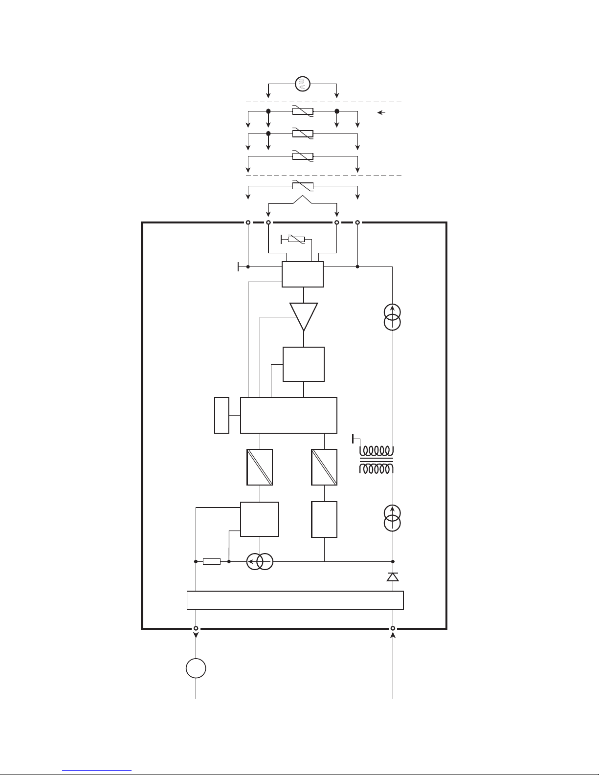
BLOCK DIAGRAM
0...16
mA
432
1
5
6
4
3
2
+
-
+
-
mV
mA
M UX
4 mA
5331
PGA
D /A
C omm.
A /D
C PU
EE PRO M
Input gnd.
Supply -
4...20 mA
TC
Ext.
CJC
mV RTD, lin. R
- wire
Int.
CJC
Ex circuit, only 5331D
Supply +
7.2...35 VDC

10 5331V114-UK
PROGRAMMING
• LoopLinkisacommunicationsinterfacethatisneededforprogramming5331.
• Forprogrammingpleaserefertothedrawingbelowandthehelpfunctionsin
PReset.
• Looplinkisnotapprovedforcommunicationwithmodulesinstalledin
harzardous(Ex)areas.
Order: Loop Link
5331
1
2
*
*
Loop
Link 5909 - USB
FileProductInputOutputCommunication LanguageOption08:30:00
PRetop5331
Date:2004-8-10
043201594
PRelectronics
AnaloginputAnalogoutput
Serial no:
Inputtype:Outputtype:4-20mA
Upscale
Sensorerror:
Pt100DIN/IEC
0.00-50.00C
3-wire
1.00sec
------
Inputrange:
Connection:
Coldjunctioncomp:
Response time:
T
ag no:
Disconnect
+Vsupply
* Connected only for
on-line programming
Black
Red Yellow
Green
Input
Receiving
Equipment
Connector
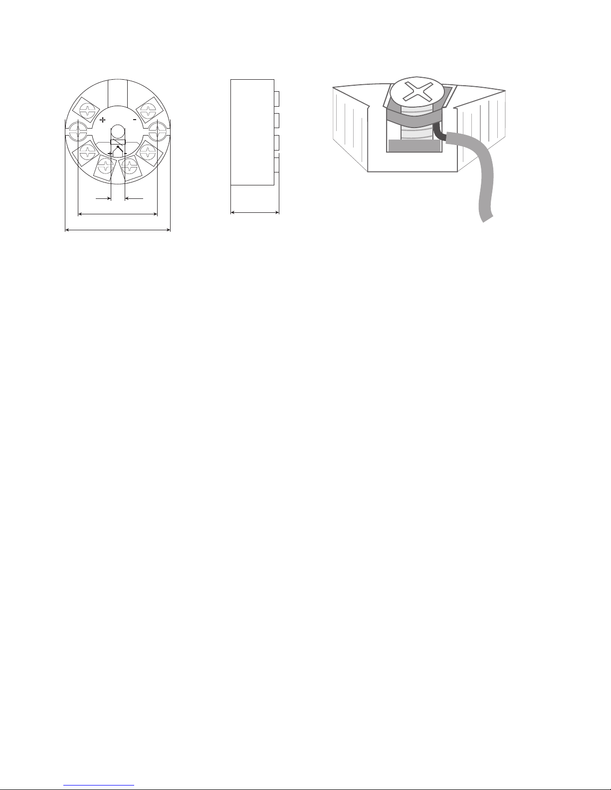
20.2 mm
+ -
+ -
ø 6 mm
33 mm
ø 44 mm
5331V114-UK 11
Mechanical specifications Mounting of sensor wires
Wiresmustbemountedbetweenthemetal
plates.

APPENDIX
ATEX Installation Drawing - 5331A
ATEX Installation Drawing - 5331D
IECEx installation drawing - 5331A
IECEx installation drawing - 5331D
FM Installation Drawing - 5331D
CSA Installation Drawing - 5331D
INMETRO Instruções de Segurança - 5331A
INMETRO Instruções de Segurança - 5331D
12 5331V114-UK

5331V114-UK 13
5331QA02
LERBAKKEN 10, 8410 RØNDE DENMARK. WWW.PRELECTRONICS.COM
Revision date:
2013-08-07
Version Revision
V2R0
Page:
1/1
ATEX Installation drawing
For safe installation of 5331A3B or 5334A3B the following must be observed. The module shall
only be installed by qualified personnel who are familiar with the national and international laws,
directives and standards that apply to this area.
Year of manufacture can be taken from the first two digits in the serial number.
ATEX Certificate KEMA 10ATEX 0002 X
Marking
Standards EN 60079-0 : 2012, EN 60079-11 : 2012, EN 60079-15 : 2010
Special conditions for safe use.
For type of protection Ex nA, the transmitter shall be mounted in a metal enclosure providing a
degree of protection of at least IP54 according to EN60529.
For use in the presence of combustible dusts the transmitter shall be mounted in an enclosure
providing a degree of protection of at least IP6X in accordance with EN60529, the surface
temperature of the outer enclosure is 20 K above the ambient temperature.
For an ambient temperature ≥60ºC, heat resistant cables shall be used with a rating of at least
20 K above the ambient temperature.
T4: -40 ≤Ta ≤85ºC
T6: -40 ≤Ta ≤60ºC
II 3 G Ex nA [ic] IIC T4 … T6 Gc
II 3 G Ex ic IIC T4…T6 Gc
II 3 D Ex ic IIIC Dc
Terminal: 3,4,5,6
Ex nA [ic]
Uo: 9.6 V
Io: 25 mA
Po: 60 mW
Lo: 33 mH
Co: 2.4 μF
Terminal: 1,2
Ex nA
Umax ≤35 VDC
Terminal: 1,2
Ex ic
Ui = 35 VDC
Ii = 110 mA
Li = 10 μH
Ci = 1.0 nF
14 5331V114-UK
5331QA01
LERBAKKEN 10, 8410 RØNDE DENMARK. WWW.PRELECTRONICS.COM
Revision date:
2013-08-07
Version Revision
V2R0
Page:
1/2
ATEX Installation drawing
For safe installation of 5331D or 5334B the following must be observed. The module shall only be
installed by qualified personnel who are familiar with the national and international laws, directives
and standards that apply to this area.
Year of manufacture can be taken from the first two digits in the serial number.
ATEX Certificate KEMA 06ATEX 0062 X
Marking
Standards EN 60079-0 : 2012, EN 60079-11 : 2012, EN 60079-26 : 2007,
EN 60079-15 :2010
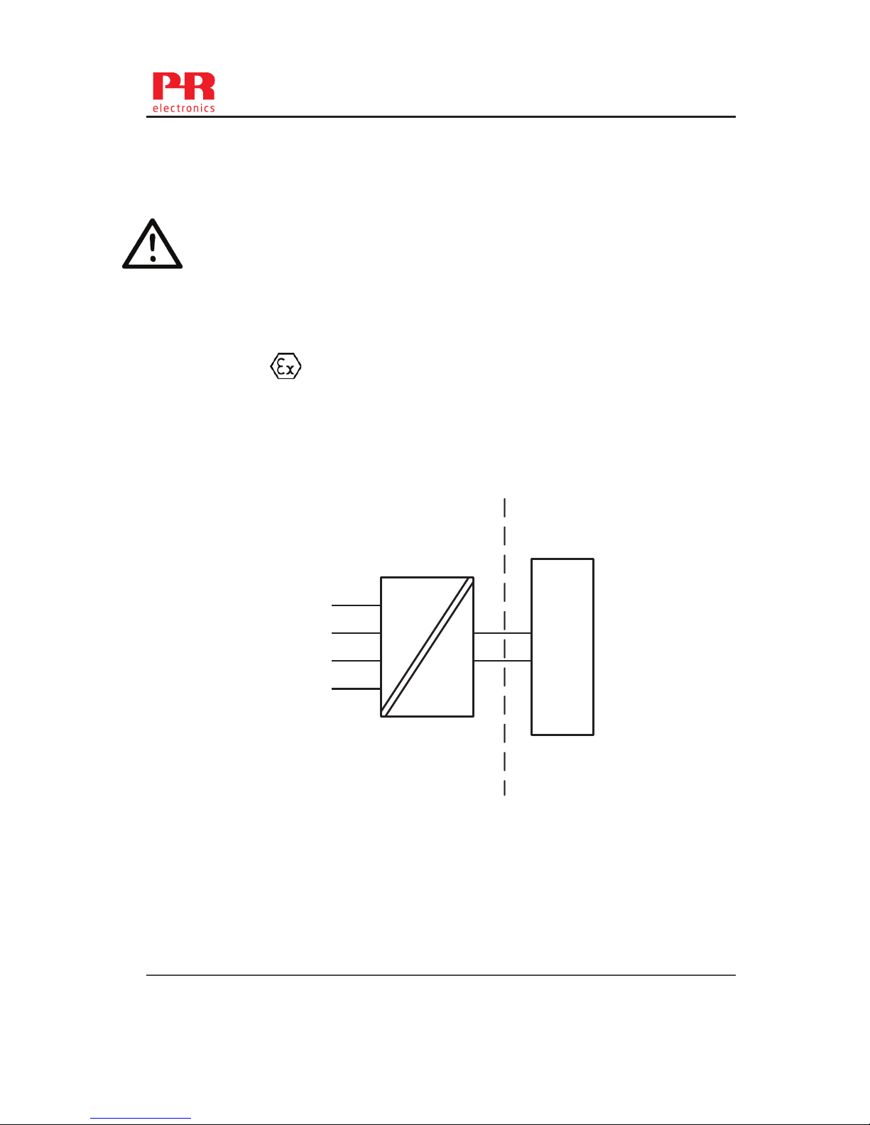
Non Hazardous Area
Hazardous area
Zone 0, 1, 2, 20, 21, 22
II 1 G Ex ia IIC T4...T6 Ga
II 1 D Ex ia IIIC Da
II 1 M Ex ia I Ma
1
2
6
5
4
3
+
-
Barrier
5331D
5334B
Terminal: 3,4,5,6
Uo: 9.6 VDC
Io: 25 mA
Po: 60 mW
Lo: 33 mH
Co: 2.4μF
Terminal: 1,2
Ui: 30 VDC
Ii: 120 mA
Pi: 0.84 W
Li: 10 μH
Ci: 1.0 nF
T4: -40 ≤ Ta ≤ 85ºC
T6: -40 ≤ Ta ≤ 60ºC

5331V114-UK 15
5331QA01
LERBAKKEN 10, 8410 RØNDE DENMARK. WWW.PRELECTRONICS.COM
Revision date:
2013-08-07
Version Revision
V2R0
Page:
2/2
Installation notes.
The sensor circuit is not infallibly galvanic isolated from the input circuit. However, the galvanic
isolation between the circuits is capable of withstanding a test voltage of 500Vac during 1
minute.
In a potentially explosive gas atmosphere, the transmitter shall be mounted in an enclosure in
order to provide a degree of protection of at least IP20 according to EN60529.
If the transmitter is installed in an explosive atmosphere requiring the use of equipment of
category 1 G, 1 M or 2 M, and if the enclosure is made of aluminum, if must be installed such,
that ignition sources due to impact and friction sparks are excluded.
if the enclosure is made of non-metallic materials, electrostatic charging shall be avoided.
For installation in a potentially explosive dust atmosphere, the following instructions apply:
The transmitter shall be mounted in a metal enclosure form B according to DIN43729 that is
providing a degree of protection of at least IP6X according to EN60529, that is suitable for the
application and correctly installed.
Cable entries and blanking elements shall be used that are suitable for the application and
correctly installed.
For an ambient temperature ≥ 60ºC, heat resistant cables shall be used with a rating of at least
20 K above the ambient temperature.
The surface temperature of the enclosure is equal to the ambient temperature plus 20 K, for a
dust layer with a thickness up to 5 mm
5331QI02
LERBAKKEN 10, 8410 RØNDE DENMARK. WWW.PRELECTRONICS.COM
Revision date:
2013-06-03
Version Revision
V1R0
Page:
1/1
IECEx Installation drawing
For safe installation of 5331A or 5334A the following must be observed. The module shall only be
installed by qualified personnel who are familiar with the national and international laws,
directives and standards that apply to this area.
Year of manufacture can be taken from the first two digits in the serial number.
Certificate IECEx DEK 13.0035X
Marking
Standards IEC 60079-0 : 2011, IEC 60079-11 : 2011, IEC 60079-15 : 2010
Installation note:
For installation in a potentialy explosive gas atmosphere, the following instructions apply:
For nA installation the transmitter must be installed in an metal enclosure, e.g. a form B
enclosure providing a degree of protection of at least IP54 according to IEC60529 or in an
enclosure with type of protection Ex n or Ex e.
For ic installation the transmitter must be installed in enclosure providing a degree of
protection of at least IP20 according to IEC60529 and that is suitable for the application.
Cable entry devices and blanking elements shall fulfill the same requirements
For an ambient temperature ≥60ºC, heat resistant cables shall be used with a rating of at
least 20 K above the ambient temperature.
For installation in a potentially explosive dust atmposphere, the following instructions apply:
The surface temperature of the enclosure is equal to the ambient temperature plus 20 K, for a
dust layer with a thickness up to 5 mm.
The transmitter must be mounted in a enclosure according to DIN 43729 that provides a
degree of protection of at least IP6X according to IEC60529, and that is suitable for the
application. Cable entry devices and blanking elements shall fulfill the same requirements.
T4: -40 ≤Ta ≤85ºC
T6: -40 ≤Ta ≤60ºC
Ex nA [ic] IIC T4..T6 Gc
Ex ic IIC T4..T6 Gc
Ex ic IIIC Dc
Terminal: 3,4,5,6
Uo: 9.6 V
Io: 25 mA
Po: 60 mW
Lo: 33 mH
Co: 2.4 μF
Terminal: 1,2
Ex nA
Umax =35 VDC
Terminal: 1,2
Ex ic
Ui = 35 VDC
Ii = 110mA
Li = 10 μH
Ci = 1.0 nF
16 5331V114-UK

5331QI01
LERBAKKEN 10, 8410 RØNDE DENMARK. WWW.PRELECTRONICS.COM
Revision date:
2013-06-03
Version Revision
V1R0
0Page:
1/2
IECEx Installation drawing
For safe installation of 5331D or 5334B the following must be observed. The module shall only be
Installed by qualified personnel who are familiar with the national and international laws, directives
and standards that apply to this area.
Year of manufacture can be taken from the first two digits in the serial number.
.
Certificate IECEx DEK 13.0035X
Marking
Standards IEC 60079-0 : 2011, IEC 60079-11 : 2011, IEC 60079-26:2006
Non Hazardous Area
Hazardous area
Zone 0, 1, 2, 20, 21, 22, M1
Ex ia IIC T4…T6 Ga
Ex ia IIIC Da
Ex ia I Ma
1
2
6
5
4
3
+
-
Barrier
5331D
5334B
Terminal: 3,4,5,6
Uo: 9.6 VDC
Io: 25 mA
Po: 60 mW
Lo: 33 mH
Co: 2.4 μF
Terminal: 1,2
Ui: 30 VDC
Ii: 120 mA
Pi: 0.84 W
Li: 10 μH
Ci: 1.0 nF
T4: -40 ≤Ta ≤85ºC
T5: -40 ≤Ta ≤60ºC
T6: -40 ≤Ta ≤45ºC
5331V114-UK 17

5331QI01
LERBAKKEN 10, 8410 RØNDE DENMARK. WWW.PRELECTRONICS.COM
Revision date:
2013-06-03
Version Revision
V1R0
0Page:
2/2
Installation notes.
The sensor circuit is not infallibly galvanic isolated from the input circuit. However, the galvanic
isolation between the circuits is capable of withstanding a test voltage of 500Vac during 1
minute.
In a potentially explosive gas atmosphere, the transmitter shall be mounted in a metal form B
enclosure in order to provide a degree of protection of at least IP20 according to IEC60529. If
however the environment requires a higher degree of protection, this shall be taken into
account.
If the transmitter is installed in an explosive atmosphere requiring the use of equipment
protection level Ga, Ma and Mb, and if the enclosure is made of aluminum, it must be installed
such, that ignition sources due to impact and friction sparks are excluded.
For installation in a potentially explosive dust atmosphere, the following instructions apply:
For explosive dust atmospheres, the surface temperature of the outer enclosure is 20 K above
the ambient temperature.
The transmitter shall be mounted in a metal enclosure form B according to DIN43729 that is
providing a degree of protection of at least IP6X according to IEC60529, that is suitable for the
application and correctly installed.
Cable entries and blanking elements shall be used that are suitable for the application and
correctly installed.
For an ambient temperature ≥60ºC, heat resistant cables shall be used with a rating of at least
20 K above the ambient temperature.
18 5331V114-UK
This manual suits for next models
2
Table of contents
Other PR Transmitter manuals


Popular Transmitter manuals by other brands


Uniq Accesory
Uniq Accesory UniqCar user guide

Microframe Corporation
Microframe Corporation 3061 Series operating manual

Stahl
Stahl 9182 Series operating instructions

MTT
MTT MS3720-01 user manual

Technical Materiel Corporation
Technical Materiel Corporation SBT-1K Technical manual

Honeywell
Honeywell XNX Technical manual