Aichi SR-123J User manual

SELF-PROPELLED
CRAWLEF TYPE
t'itORK PLATFoRro

THIS SAFETY ALERT SYMBOL MEANS ATTENTION TO A HAZARD! YOUR SAFETY IS
INVOLVED BE ALERT.
OPERATOR QUALIFICATIONS
OPERATOR SAFETY REMINDERS
),
Red Danger Labels are used to indicate the presence of a hazard that will cause death or
serious injury.
Orange Warning Labels are used to indicate the presence of a hazard that may cause death or
serious injury.
Yellow Caution Labels are used to indicate the presence of a hazard that will or may cause
serious personal injury or damage to the machine.
Only authorized people who have been trained should use this work platform. Safe use of this
work platform requires the operator to understand operating procedures, operators responsibil-
ity for maintenance, and limitations and warnings. The operator must understand and be
familiar with this manual, its warnings, and all warnings and instructions on the work platform.
(*perators must also be familiar with employers work rules and related government regulations
ndbe able to demonstrate his/her ability to understand and operate this make and model work
pl--,qferm in the presence of a qualified person.
The National Safety Council reminds us that most accidents are caused by the failure of some
individuals to follow simple and fundamental safety rules and precautions. Commonsense
dictates the use of protective clothing when working on or near machinery. Use proper safety
devices to protect eyes, ears, hands, and feet.
You, as a careful operator, are the best insurance against an accident. Therefore, proper usage
of this work platform is mandatory. The following pages of this manual should be read and
understood completely before operating this work platform. Any modifications from the original
design are strictly forbidden without written permission from the manufacturer.
2

TIP-OVER HAZARD
DO NOT RAISE PLATFORM ON UNEVEN ORSOFTSURFACES. DO
NOTDRIVE ONTO UNEVEN OR SOFT SURFACES WHEN ELEVATED. DO NOT RAISE PLATFORMINWINDY ORG'USTYCONDMONS.
DO NOTUSE INMORE THAN28 MPH(12.5 WS)WINDS
i -- - ---' ,,
,,,, ,
i1,1 ,
■ — t:
\
DO NOTRAISE PLATFORMONSLOPE ORDRIVE
ONTOSLOPEWHENELEVATED.
ELECTROCUTION HAZARD
THIS MACHINE IS NOT INSULATED.
MAINTAIN SAFE CLEARANCES FROM
ELECTRICAL POWER LINES AND
APPARATUS. YOU MUST ALLOW FOR
WPLOATRFKOFIPLAMTSFWOARYM, RDOOCEKS, ONORTSAPGRO. \ITIHDISE
PROTECTION FROM CONTACT WITH OR
PROXIMITY TO AN ELECTRICALLY
CHARGED CONDUCTOR.
,
, - , . ..
e .
i.
Wil
•.,-. •-
k
DO NOT DRIVE NEAR DROP-OFFS, HOLES,
OPENELEVATOR SHAFTS OR LOADING DOCKS.
- , ,
\ĺ ,..,
. , I 4 4 1
,.- ,
t ',II ---I., ---- '
■
‘, ,___..- '
WHEN LOADING ORUNLOADING THE WORK PLATFORM.
ALWAYS HAVE THE COUNTERWEIGHT UPHILL.
VOLTAGE RANGE MINIMUM SAFE APPROACHDISTANCE
(PHASETOPHASE) (FEET) (METERS)_
AVOIDCONTACT
, -
0TO300V
OVER300VTo50KV 10 3 05
OVEF150KVTO200KV 15 4 6
—- 6 i
OVER 200KV TO350KV 20
OVER350KVTO 500KV 25 762
OVER500KVTO 750KV 35 1067
OVER 750KV TO 1000KV 45 1372
FAILURE TO AVOID THESE HAZARDS WILL RESULT IN
SERIOUS INJURYOR DEATH. .i.,s.
PLATFORM WARNING LABELS
ATTACH
SAFETY
",NYARD
HERE
491-0000149
if
!' gl; 1'1
—•
CHYOI__;J:L) 77 ARNESS
OPERATING THIS MACHINE WITHOUT THE CORRECT SAFETY
HARNESS ATTACHMENT COULD RESULT IN SERIOUS INJURY
OR DEATH.
NOTE
Aichi is continuously improvina and expanding
product features on its equipment; therefore,
specifications and dimensions are subject to
change without notice.
Figure "I. Platform Labels
3
491-0000148

WARN!
. DO NOT EXCEED RATED LOAD.
. DO NOT USE IF WORK PLATFORM IS NOT WORKING PROPERLY OR IF ANY PART IS
DAMAGED, MISSING, ORWORN.
. DO NOT USE NEAR MOVING VEHICLES OR CRANES.
4. DO NOT USE WITHOUT GUARDRAILS, MIDRAILS, ENTRYGATE, OR MIDRAIL BAR INPLACE.
5. DO NOT USE UNDER THE INFLUENCE OF DRUGS OR ALCOHOL.
6. DO NOT SIT OR STANDON THE GUARDRAILS.
7. DO NOT BYPASS OR OVERIDE SAFETY DEVICES.
8. DO NOT RAISE THE PLATFORM WHILETHE WORK PLATFORM IS ON A TRUCK, FORKLIFT,
OTHER DEVICE OR VEHICLE.
9. DO NOT USE A LADDER, SCAFFOLDING, OR OTHERDEVICES TO INCREASE THE SIZE OR
WORKING HEIGHT OF THE WORK PLATFORM.
10. DO NOT ATTACH CHAINS, ROPES, OR CABLES TO THE PLATFORM OR RAILINGSOR USE
AS A CRANE.
11. DO NOT LEAVE THE WORK PLATFORM UNATTENDED WITH THE KEY INTHE KEY SWITCH.
ISR 700
PLATFORM CAPACITY
(UNRESTRICTED-EVENLY DISTRIBUTED)
MAXIMUM NUMBER OF PERSONS 2-NOT TO EXCEED 550 LBS.(250KG.)
MAXIMUM WEIGHT OF PERSONS AND EQUIPMENT 550 LBS.(250KG.)
ISR-403-ISR-602
OTHER HAZARDS
FAILURE TO AVOID THESE HAZARDS MAY RESULT
IN DEATH OR SERIOUS INJURY!
550LBS.(250KG.)
PLATFORM CAPA. fr-TJ
(UIRESTRk;TED-EVENLY DISTRIBUYEb)
MAXIMUM NUMBER OF PERSONS 2-NOT TO EXCEED 440 LBS.(200KG.)
MAXIMUM WEIGHT OF PERSONS AND EQUIPMENT 440 LBS.(200KG.)
440LBS.(200KG.
Figure 1-A Platform Labels
4
491-0000151
491-0000146 I
491-0000147

You are required by ANSI/SIA A92.5 1990 to read and understand YOUR RESPONSIBILITIES
in the OPERATORS MANUAL before you use or operate this work platforrn. The Operators
Manual must always be attached to the work platform.
FAILURE TO COMPLY with your REQUIRED RESPONSIBILMES in the use and operation of
the work platform could result in DEATH OR SERIOUS INJURY.
FAILURE TO AVOID THIS HAZARD WILL RESULT IN DEATH OR SERIOUS INJURY!
(HIS MACHINE IS NOT INSULATED. MAINTAIN SAFE CLEARANCES FROM ELECTRICAL
POWER LINES ANDAPPARATUS. YOU MUST ALLOW FOR PLATFORM SWAY, ROCK, OR
SAG. THIS WORK PLATFORM DOES NOT PROVIDE PROTECTION FROM CONTACT
WITH OR PROXIMITY TO AN ELECTRICALLY CHARGED CONDUCTOR.
VOLTAGL:h NGE
(PHASE TO PHASE)
o TO 300V
OVER 300V TO 50KV
OVER 50KV TO 200KV
OVER 200KV TO 350KV
OVER 350KV TO 500KV
OVER 500KV TO 750KV
OVER 750KV TO 1000KV
1\ WARNING
ELECTROCUTION HAZARD
MINIMUM SAFE APPROACH DISTANCE
(FEET)
10
15
20
25
35
45
5
(METERS)
AVOID CON¡TACT
3.05
4.6
6.1
7.62
10.67
13.72

Model SR-123J ISR-403J
W. it Overall weight 8,600 kgf 18,960 lbs
Max. ground contact pressure 0.74 kgf / cm2 11 PSI
Model A-4JB1-PAA17 <
Total displacement 2,771 cc 169 in'
Output power 56.4 PS / 2,200 rpm 41.5kw / 2,200 rpm
Output torque 19.4 kgf-m /1,800 rpm 140 ft-lb / 1,800rpm
Engine oil capacity 6.6 liters 1.74 gallons
Cooling water capacity 11.0 liters 2.91 gallons
Fuel tank capacity 108 liters 28.5 gallons
Engine speed 1,200"-2,300 rpm <
Battery DC12y / 70AH X 2
Platform Rated load 250 kgf or
2 persons + Tools ( 90 kgf ) 550 lbs or
2 persons + Tools ( 200 lbs )
Max. allowable side force 41 kgf ( 400N ) 90 lbs
Inner dimensions 1,800 X 750 X 1,100 mm 5.9 X 2.46 X 3.6 ft
Rotation angle 180° <
Maximum floor height 12.0 meters 39 ft 4 in
Maximum working radius 11.5 meters 37 ft 8 in
isT Boom length 5.0-9.96 meters 32 ft 8 in
Boom angle -20-70 degrees
Fly jib angle -44-70 degrees <
Rotation angle 360° continuously
-rational
ed Elevation UP 45 ± 6 seconds / stroke 35 ±6 seconds /stroke
DOWN 55 ± 6 seconds / stroke 35 ± 6 seconds /stroke
Extension OUT 22 ± 4 seconds / stroke
IN 22 ± 4 seconds / stroke
Rotation C.W. 120 ± 15 seconds / 1 turn 60 ± 5 seconds / 1 turn
C.C.W. 120 ± 15 seconds / 1 turn 60 ± 5 seconds / 1 turn
'
Travelling High
speed Forward 24 ± 3 seconds / 10 m 22±3seconds/10yards
Reverse 24 + 3 seconds / 10 m 22±3seconds/10yards
Low
speed Forward 51 ± 8 seconds / 10m 47 ± 7 seconds / 10 yards
Reverse 51 + 8 seconds / 10m 47±7 seconds / 10 yards
Pl'atform rotation Right 20 ± 4 seconds / stroke
Left 20 ± 4 seconds / stroke K
Fly jib Up 20± 4 seconds / stroke <
Down 15 ±3 seconds / stroke <
SPECIFICATIONS
1 -3

In
to
cr)
o
o
to
1-2
(„E-,L ) N U
... .
mum",11
1
111-01.-•E
i iiiii I
I-i - i
1
i i i ■ M u I I I _______ 11
.......1IIII .-
11119mir
-winig' 11
A, I
. 4 - - - - IIMIlffi l l i d l l
(,;z-3) 0L81
OZt t
0
4 " ;
•
11 1
r_r^
71- ,1111—^- 712- 1
It,
Ln
o
0 0
0 lb
(„g -,E)
01Z

3600
(-
iiksVit
ilk
'k 4 k
, ,
as%;'
(,,4
-
I -v-k\ N44vr
\k... 14.
v L 1 \ \ 1
t -%■•■■
4—
ph. wkN
—11-
"‘"4,130HP
1,07,,, \S,
,.....\ ,
,
M i l l i b b .
I..0 4
A N I T I M O
■1.
-"gi l l V A N i l w l
ki"S"
NI\ I
lc
)11
M I A i r
,
Travelling restriction arcas
(32.8') l O
(164)5
O
Rated load : 250kgf (550Ibs)
O(16.4.) 1 0 (m)
(32.8) (ft)
NOTE;
The travelling is disabled when the platform is positioned within
the area shown in the above chart and the machine tilts
over 5 degrees.
1-5

SECTION 1
IiiITRODUCTION
PURPOSE OF EQUEIMENT
Aichi Work Platforms are designed to transport and raise
personneland tools to overhead work areas.
USE OF EQUIPMENT
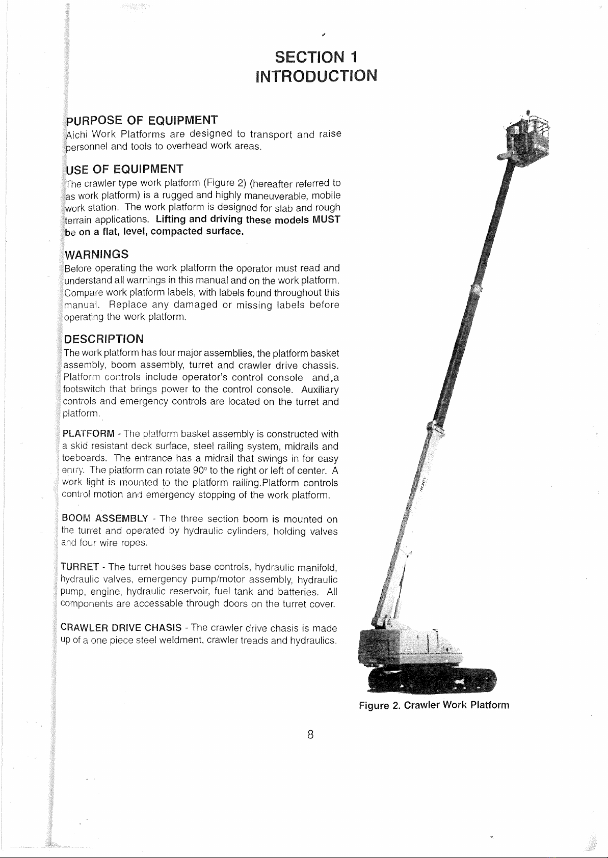
The crawler type work platform (Figure 2) (hereafter referred to
as work platform) is a rugged and highly maneuverable, mobile
work station. The work platform is designed for slab and rough
terrain applications. Lifting and driving these models MUST
1:),: on a flat, level, compacted surface.
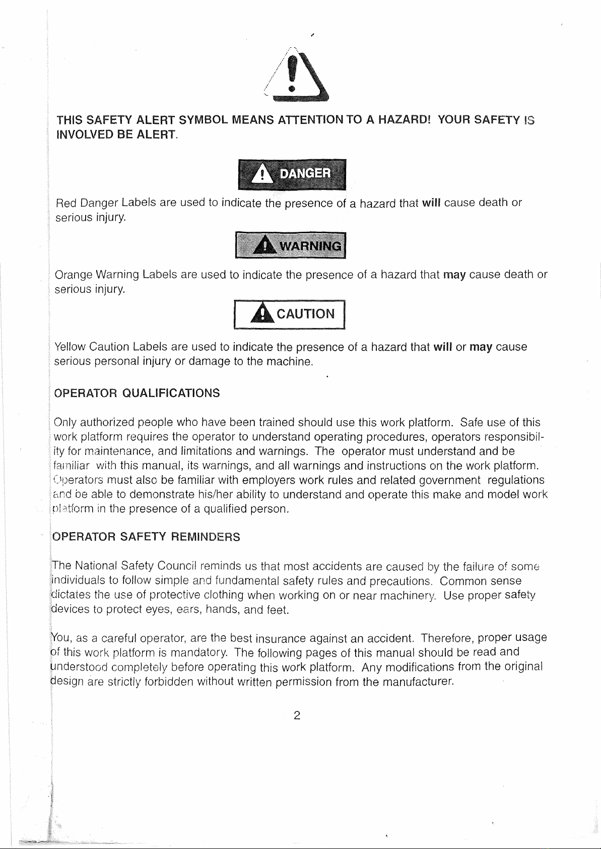
WARNINGS
Before operating the work platform the operator must read and
understand all warnings in this manual and on the work platform.
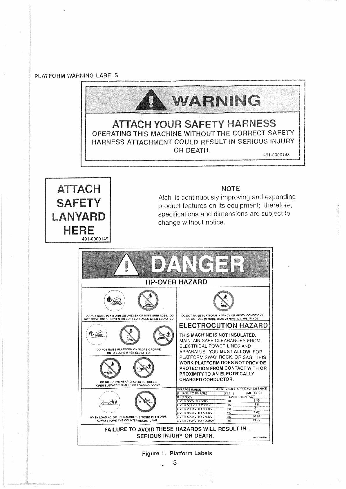
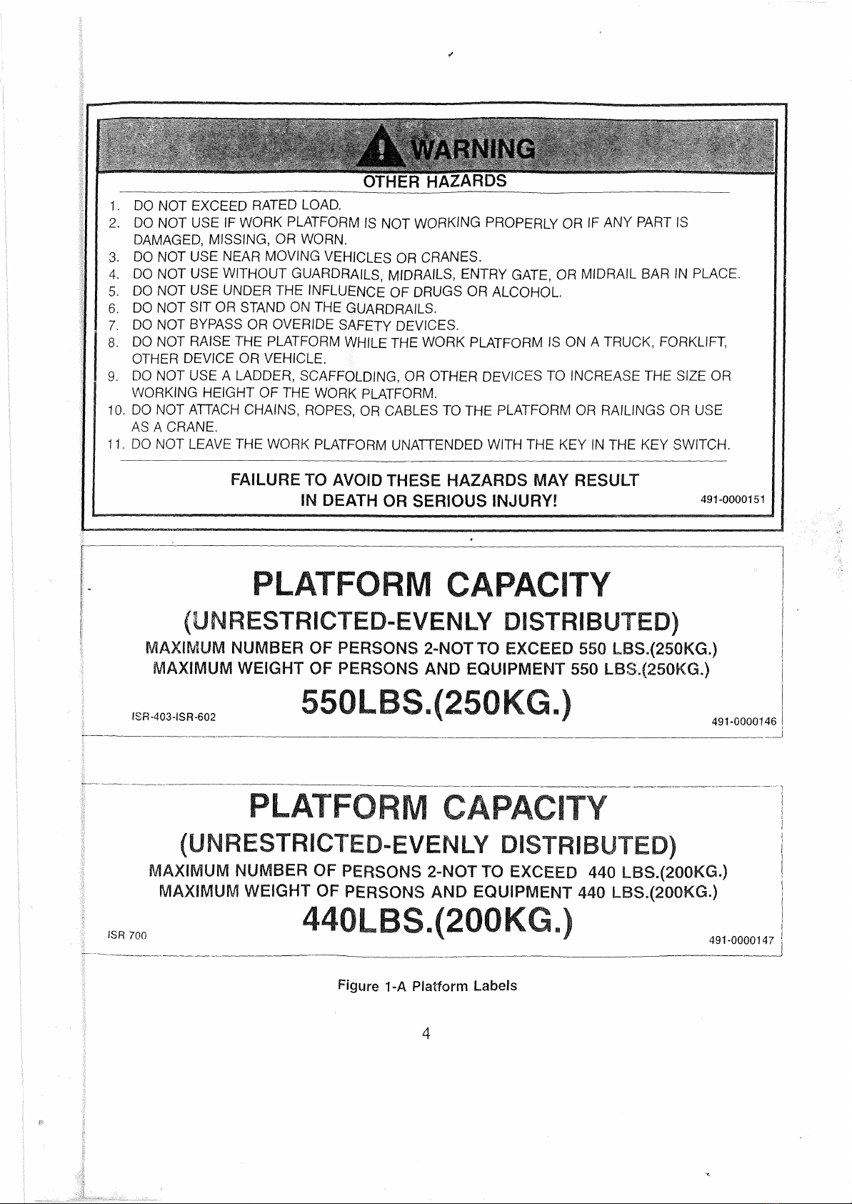
Compare work platform labels, with labels found throughout this
manual. Replace any damaged or missing labels before
operating the work platform.
DESCRIPTION
The work platform has four major assemblies, the platform basket
assembly, boom assembly, turret and crawler drive chassis.
Platform controls include operator's control console and ,a
footswitch that brings power to the control console. Auxiliary
controls and emergency controls are located on the turret and
platform.
PLATFORM - The platform basket assembly is constructed with
a skid resistant deck surface, steel railing system, midrails and
toeboards. The entrance has a midrail that swings in for easy
entry. The piatform can rotate 90° to the right or left of center. A
work light is mounted to the platform railing.Platform controls
contiol motion and emergency stopping of the work platform.
BOOM ASSEMBLY - The three section boom is mounted on
the turret and operated by hydraulic cylinders, holding valves
and four wire ropes.
TURRET - The turret houses base controls, hydraulic manifold,
hydraulic valves, emergency pump/motor assembly, hydraulic
pump, engine, hydraulic reservoir, fuel tank and batteries. All
components are accessable through doors on the turret cover.
CRAWLER DRIVE CHASIS - The crawler drive chasis is made
up of a one piece steel weldment, crawler treads and hydraulics.
8
Figure 2. Crawler Work Platform

CONTINUE ONLY IF YOU
UNDERSTAND WHAT YOU
HAVE JUST READ
SECTION 2
OPERATION
OPERATOR QUALIFICATIONS
Only authorized people who have been trained should use this work platform. Safe use of this work platform
requires the operator to understand operating procedures, operators responsibility for maintenance, limitations and
warnings. The operator must understand and be familiar with this manual, its warnings, and all warnings and
instructions on the work platform. Operator also MUST be familiar with employer's work rules and related government
regulations and be able to demonstrate his/her ability to understand and operate THIS make and model work
platform in the presence of a qualified person.
OPERATING CONTROL IDENTIFICATION
The description in Figure 4 is for identification, explanation and locating purposes only. A qualified operator MUST
read and completely understand these controls before operating this work platform. "OPERATING PROCEDURES"
for operating this work platform are covered in the operating procedure section, on Pages 16 through 20.
10

LOWER CONTROL PANEL
-11
Figure 4. Lower Control Panel
1. HOUR METER
2. REMOTE CONTROL SOCKET FOR TRAVEL FROM BASE (OPTION)
3. BASE/PLATFORM CONTROL SELECTOR SWITCH
4. BOOM ELEVATION/LOWERING SWITCH
5. EMERGENCY PUMP SWITCH
6. BOOM EXTENSION/RETRACT1ON SWITCH
7. HIGH THROTTLE SWITCH
8. BOOM ROTATION SWITCH
9. EMERGENCY STOP BUTTON
10. CHARGE INDICATOR LAMP
11. WATER TEMPERATURE LAMP
12. ENGINE OIL PRESSURE LAMP
13. GLOW PLUG LAMP
14. ENGINE START/STOP KEY SWITCH
15. POWER LAMP
16. FUSE HOLDER

LOWER CONTROL PANEL
1. HOUR METER - Activated when the engine is started, measures engine run time.
2. REMOTE CONTROL SOCKET FOR TRAVEL FROM BASE (OPTION) - This option is used to move the
work platform from the ground position.
3. BASE/PLATFORM CONTROL SELECTOR SWITCH - This switch is used to switch power from the base
controlto platform controls. When this switch is placed in the "on position", it shuts off platform controls and
activates the base control panel.
4. BOOM ELEVATION SWITCH - This switch controls the up down movement of the boom section. When this
switch is placed in the "boom up position" the boom raises. When this switch is placed in the "boom down
position" the boom lowers.
5. EMERGENCY PUMP SWITCH - This switch operates the emergency pump motor assembly. ln the event of
a pump or engine failure this control is used to bring the boom down. The emergency pump runs only when
the switch is held in the "on" position. Select the desired function, and place the "emergency pump switch" in
the "on" position. Hold the switch on for thirty seconds, then off for thirty seconds until the work platform is
fully lowered.
DANGER
CONTINUOUS OPERATION OF THE EMERGENCY PUMP UNIT COULD CAUSE DAMAGE TO THE D.C.
MOTOR.
6. BOOM EXTENSION SWITCH - Thisswitch is used to "extend" and "retract" the boom. To extend the boom,
select and hold the boom "extend" switch in the "extend" position until the desired position is reached.
Release the switch to stop. To retract the boom select and hold the boom "retract" switch in the "retract"
position untilthe desired position is reached. Release the switch to stop.
HIGH THROTTLE SWITCH -Use the accelerator switch to increase engine R.P.M. by selecting "high". Select
"low" to decrease engine R.P.M.
BOOM ROTATION SWITCH - This switch is used to rotate the boom clockwise or counter clockwise. To
"rotate" the boom select "left" or "right" with the "boom rotate switch" hold until the desired position is reached.
TO stop release switch.
9 . EMERGENCY STOP BUTTON SWITCH - This switch disconnects power when pushed. When pressed this
push button switch disconnects power to the upper and lower controls and stops the engine. To restore
power pull the "emergency stop button" out, step on the "foot switch, and the "power lamp" will glow.
10.. CHARGE INDICATOR LAMP - This lamp will shutoff when the engine is running. If this lamp is glowing
when the engine is running, shut the engine down and check for the problem.
11. WATER TEMPERATURE LAMP - This lamp will shut off when the engine is running. If this lamp is glowing
when the engine is running, shut the engine down and check for the problem.
12, ENGINE OIL PRESSURE LAMP - This lamp will shut off when the engine is running. If this lamp is glowing
when the engine is running, shut the engine down and check for the problem.
12

LOWER CONTROL PANEL (continued)
13. GLOW PLUG LAMP - This lamp will tell the operator when it is safe to start the engine. Turn the "engine
start/stop key switch" to the "H" position until the lamp glows, then start the engine.
14. ENGINE START/STOP KEY SWITCH - This switch is used to turn power on for the work platform, and heat
the "glow plug" for the engine. Turning this switch to the off position disconnects power to the control circuit.
Turning this switch to the "start position" starts the engine. Turning this switch to the "H" position heats the
"glow plugs" to start cold engines.
15. POWER LAMP - This lamp will glow when the "key switch" is turned on and the "emergency stop switch" is in
the operating position.
16. FUSE HOLDER - This holder houses fuses for the work platform
Figure 5. Platform Leveling Valves
1. PLATFORM LEVELING SYSTEM (BASE CONTROL IF EQUIPPED)
1.-his system keeps the platform level by using an upper and lower leveling cylinder, double pilot operated
check valve and combination valve for adjustment.
13
Before using the work platform make sure the platform is level. If the platform is more than three (31
degrees out of level, it must be adjusted. The work platform must be on firm level surface with nothing in
the basket when this adjustment is made.
1. Adjustment is performed at the lower control box.
2. Turn the two (2) valves on the turntable counter clockwise and open fully.
3. If the platform is tilted forward, operate the "Boom Retraction Switch" until the platform is level,
then fullyclose both valves by turning clockwise.
4. If the platform is tilted backwards, operate the "Boom Extension Switch" until the platform is level,
then fully close both valves by turning clockwise.
5. Raise the platform from the base controls several times to make sure the platform remains level.
6. If the platform doesn't remain level after the adjustment is made there may be air in the system. To
bleed the air, open the two (2) valves on the turntable by turning counter clockwise. Operate the
"Boom Extension Switch" to fully extend and fully retract the boom three or four times. Again level
the platform per instructions in step 1 thru 5. Raise the boom several times to make sure the
platform remains level. 491-0000153

Elevation control lever
Travel(L) control lever
Travel(R) control lever
Emergency stop s/w
Engine start s/w
lauf
Rotation control lever
Extension control lever
Emergency pump s/w
Fly jib s/w
ĺl
Platform level s/w </
`, •
wy to
Platform rotation s/w
3
Horn s/w
Accelerator s/w
Working light s/w
ok\
904.
Bview
A

PLATFORM CONTROLS
•. FOOT SWITCH
2. HIGH THROTTLE SWITCH
3. FORWARD/REVERSE TRAVEL CONTROL
LEVERS
4. LEFT TRACK CONTROL
5. ENGINE START SWITCH
6. POWERLAMP
7. RIGHT TRACK CONTROL
8. BOOM ELEVATION/LOWERING CONTROL
LEVER
9. BOOM ROTATIONCONTROL LEVER
10. BOOM EXTENSION/RETRACTION LEVER
11. R A I-FORM ROTATIONSWITCH
12. EMERGENCY STOP SWITCH
•3. EMERGENCY PUMP SWITCH
14, HORN ALARM BUTTON
15. WORKLIGHT SWITCH
16. PLATFORM LEVEL SWITCH
PLATFORM OPERATING CONTROLS
Figure 6. Platform Controls
14
Foot Switch
1. FOOT SWITCH - All controls except emergency stop, horn and the working lights are interrupted through this
switch. During normal operation, when the foot switch is depressed, it provides power to the platform controls
. and locks out operation of the base controls until it is released.
2. HIGH THROTTLE SWITCH - The accelerator switch is used to increase and lower engine R,P.M..
A. With the switch in the lowposition engine R.P.M. is 1200 R.P.M.
B. With the switch in the high position engine R.P.M. is 2300 R.P.M.
C. With the switch in the auto position engine R.P.M. is 1800 R.P,M.(if equipped)
3, FORWARD/REVERSE TRAVEL CONTROL LEVERS - These two levers are used to move the work
latform in fonNard or reverse directions, and to steer the machine right and left.
4. LEFT TRACK C:ONTROL - Pushing forward will cause the left track to go forward. Pulling it back will cause
the left track to go in reverse.
5.. ENGINE START SWITCH- When power lamp is on pushing the engine start switch will start the engine.
6. POWER LAMP- Indicates power is on to operate upper controls.

DESCRIPTION FUNCTION OF VALVES AND SWITCHES
RELIEF VALVE PROTECT HYDRAULIC EQUIPMENT IF WORK PLATFORMIS OVERLOADED.
BOOM
ELEVATION
HOLDING VALVE
PREVENT BOOM DECENT IF HOSE IS BROKEN OR DAMAGED.
BOOM
EXTENSION
DOUBLE
HOLDING VALVE
PREVENT BOOM RETRACTION IF HOSE IS BROKEN OR DAMAGED.
PLATFORM
LEVELING
DEVICE
KEEPS PLATFORM LEVELED
OPERATION
WARNING
DEVICE
ALARMSOUNDS WHEN ANY FUNCTION ON THE WORK PLATFORM IS BEING OPERATED.
.
FOOT SWITCH INTERRUPTS ALL FUNCTIONS OPERATED FROM THE PLATFORM CONTROLS. MUST BE
DEPRESSED WITH FOOT BEFORE ANY PLATFORM CONTROL WILL WORK.
STOP BUTTON STOPS ALL OPERATING FUNCTIONS IN THE BASKET WHEN DEPRESSED.
SLOPE WARNING
DEVICE WHEN THE WORK PLATFORM REACHES A 3° ANGLE, A WARNING ALARM SOUNDSWARN-
ING THE OPERATOR.
EMERGENCY
PUMP AUXILIARY D. C. PUMP/MOTOR ASSEMBLY CAN BE USED IN THE EVENT OF MAIN PUMP OR
ENGINEFAILURE.
WARNING HORN HORN USED TO WARN PEOPLE IN WORK AREA.
FOOT SWITCH
INTERLOCK WHEN FOOT SWITCH IS DEPRESSED, PLATFORM CONTROLS CAN BE OPERATED AND BASE
CONTROLS CAN'T BE USED UNTIL FOOT IS REMOVEDFROM FOOT SWITCH.
TRAVEL SPEED
CONTROL BOOM MUST BE LOWERED BELOW HORIZONTAL AND FULLY RETRACTED TO ACHIVE
HIGH SPEED.
PLATFORM OPERATiNG CONTROLS (continued)
7, RIGHT TRACK CONTROL - Pushing forward will cause the right track to go forward. Pulling it back will
causethe right track to go in reverse.
8. BOOM ELEVATION/LOWERING CONTROL LEVER SWITCH - This switch is used to raise and lower the
boom.
9. BOOM ROTATION CONTROL LEVER - This switch is used to rotate the boorn left or right.
10. BOOM EXTENSION/RETRACTION LEVER - This lever is used to extend or retract the boom.
11. PLATFORM ROTATION SWITCH - This switch is used to rotate the platform left or right.
12. EMERGENCY STOP SWITCH - This switch is used to cut power to all controls on the work platform.
13. EMERGENCY PUMP SWITCH - This switch operates a DC power unit so the boom can be brought
down if the engine or main pump fails.
14. HORN ALARM BUTTON - This button sounds a horn on the work platform.
15. WORK LIGHT SWITCH - This switch operates the work light located on the platform railing.
16. PLATFORM LEVEL SWITCH - This switch enables the operator to level the platform if adjustment is
necessary. SAFETY DEVICES
Table 2. Safety Devices
15

OPERATING PROCEDURES
6. Do not operate under the influence of alcohol or drugs.
7. Do not operate in bad weather.
A. Strong or gusting winds
B. Heavy rain
C. Thunder•or lightening.
16
WHEN ARE YOU
AUTHORIZED AND
QUALIFIED TO OPERATE
THE WORK PLATFORM
READ ANDUNDERSTANDOPERATOR
QUALIFICATIONS
WARNING
1. Only qualified operators who have read and understand this manual should operate this machine.
2. Protective clothing should be worn before using the work platform.
3. Only qualified operators can train operators in the operation of this work platform.
4. Operators must be familiar with employers work rules, and related government regulations.
5. Keep fuel, oil, and combustible materials away from fire.
1\ DANGER
DANGER
8. Any modification to the equipment, from its original design is strictly forbidden without written permission
from the manufacturer.
.. 9. Protect all electrical components when power washing the work platform.
10. Start engine, allow to warm up at low idle before use.
.1117190420 4S96.70 48.071S ZEt t,72028 19316. 0826110 41ita.
1..\ DANGER
. Do not operate on any public street, road,highway, or railroad right of way.
DANGER
12. DANGER ELECTROCUTION HAZARD. FAILURE TO AVOID THIS HAZARD WILL RESULT IN DEATH OR
SERIOUS INJURY ! THIS MACHINE IS NOT INSULATED. MAINTAIN SAFE CLEARANCES FROM
ELFCTiTCAL POWER LINES AND APPARATUS . YOU MUST ALLOW FOR PLATFORM SWAY, ROCK,
OR SAG. THIS WORK PLATFORM DOES NOT PROVIDE PROTECTION FROM CONTACT WITH OR
PROXIMITYTO AN ELECTRICALLY CHARGED CONDUCTOR.
13. Before driving work platform check arrow plate on base of work platform. Arrow.indicates forward direction.

OPERATING PROCEDURES (CONT.)
L DANGER
14. Danger tip over hazards
A. Do not elevate or drive elevated on soft or uneven surfaces. Note: Maximum contact
pressure is 9.4 PSI on ISR-403, 11 PSI on ISR-602, and 13 PSI on ISR-700.
B. Do not pull or push against any object
C. Do not lift or lower objects with rope, cable, or chain attached to basket.
D. Do not overload, check capacity before using.
LDANGER
15. Do not elevate on more than a 5° slope. When work platform exceeds more than 3° an alarm sounds. If this
alarm sounds immediately retract and lower the boom and drive it to a level position.
16. Always wear a safety harness thats fastened properly and secured with a lanyard that is attached to the
platform.
17. Pay special attention when rotating boom. Do not place you hand between handrail of platform and any
obstacle. When operating the work platform in any direction always return to the off position and stop before
going into the opposite direction.
18. Do not operate work platform without both feet on the platform floor.
19.Donotuse aladderintheworkplatformbasket.
DANGER
LDANGER
DANGER
DANGER
20. Do not use flammable material in the work platform basket.
DANGER
21. When arc welding or using acetylene make sure work platform is protected from hot sparks or hot material
from falling on the battery, hydraulic hoses or electrical cables.
WARNING
22. Avoid the following .
A. Do not hit the work platform basket or boom while elevating, rotating, or extending.
B. Do not hit the work platform basket while traveling forward or reverse.
C. Do not use the crawler in water.
CAUTION
23. Inadvertent boom extension or retraction.
A. If the hydraulic oil temperature is high, and the boom is left extended, the boom may extend or retract
inadvertently. This is caused by oil temperature change, and is normal.
Note: In order to prevent boom extension or retraction, do not operate at high oil temperatures. Operate
extension and retraction at regular intervals. - 17

Figure 7 Foot Switch
START AND OPERATION
1. Pull the Emergency Stop Button out.
2. Select platform on the Base/Platform control selector switch.
3. Enter the platform by swinging the midrail entry bar in (if equipped), or raising the midrail entry bar.
4. Attach harness and lanyards of each occupant to the lanyard anchors.
5. Depress and hold the Footswitch.
AcUJTION
DO NOT DISABL71
FOOT SWITCH BY
JAMMING OR ANY
OTHER MEANS.
491-0000153
Figure 7A Foot Switch Label
6. FOOT SWITCH - All controls except emergency stop, horn and the working lights are interrupted through this
switch. During normal operation, when the foot switch is depressed, it provides power to the platform controls
and locks out operation of the base controls until it is released.
7. HIGH THROTTLE SWITCH- The accelerator switch is used to increase and lower engine R.P.M..
A. With the switch in the lowposition engine R.P.M. is 1200 R.P.M.
B. With the switch in the high position engine R.P.M. is 2300 R.P.M.
C. With the switch in the auto position engine R.RM. is 1800 R.P.M.(if equipped)
NOTE: When elevating, rotating or extending, speed automatically shifts to 1800 R.P.M. When driving
forward/reverse control speed automatically shifts to 2300 R.RM.
8. FORWARD/REVERSE TRAVEL CONTROL LEVERS - To travel forward use the two travel levers. The
farther you push them forward the faster you travel. To travel in reverse pullthe two levers in reverse. The
farther you pull them in reverse the faster you travel.
When the turn table is rotated 180 degrees the control levers operate in the opposite direction of travel.
Always check the arrow on the base, it indicates "FORWARD" direction. Avoid sudden direction changes.
9. LEFT TURN (Reverse stopped) - With the "right" lever in the stop position, pull the "left" lever into reverse.
10. LEFT TURN (Forward stopped) - With the "left" lever in the stop position, push the "right" lever forward.
11. RIGHT TURN (Reverse stopped) - With the "left" lever in the stop position, pull the "right" lever into reverse.
18

START AND OPERATION (continuO)
12, RIGHT TURN (Forward stopped) - With the "right" lever in the stop position, push the -left" lever forward.
13. LEFT TURN (Spin stopped) - Pull the "left" lever to reverse and push the "right" lever forward.
14. RIGHT TURN (Spin stopped) - Pull the "right" lever to reverse and push the ''left" lever forward.
15. BOOM ELEVATION/LOWERING CONTROL LEVER - To raise the boom push the "Elevation Control Lever"
to the "up" position. When the desired height is reached return the lever to the stop position.
To lower the boom pull the "Elevation Control Lever" to the "down" position. When the desired position is
reached return the lever to the stop position.
16. BOOM ROTATION CONTROL LEVER - To rotate the boom select "right" or "left.' direction. Return the lever
to stop when the desired position is reached.
L\ DANGER
Before rotating the boom check for people and obstructions in the work area.
17. BOOM EXTENSION/RETRACTION LEVER - To extend the boom, move the lever to "out" position until the
desired position is reached. Return the lever to the stop position.
To retract the boom move the lever to the "in" position until the desired position is reached. Return the lever
to the stop position.
18 PLATFORM ROTATION - To rotate the platform select "left" or "right" with the rotation lever and hold until the
desired position is reached. Return the lever to stop position.
1_\. DANGER
When driving in forward or reverse always place the platform in the forward direction as designated by
the direction arrow on the base of the work platform.
19. EMERGENCY STOP - When pressed, this push-button switch disconnects power to the upper and lower
controls and stops the engine. To restore power pull the emergency stop button out, so it is in the operating
mode.
20. EMERGENCY PUMP OPERATION - ln the event of a main pump or engine failure this control is used to
bring the boom down. The emergency pump runs only when the switch is held in the "on" position. Select
the desired function and place the Emergency Pump Swich" in the on position. Hold the switch on for thirty
(30) seconds, then off for thirty (30) seconds until the work platform is fully lowered.
▪DANGER
Continuous operation of the "Emergency Pump Unit" could cause damage to the D.C. motor.
21. HORN ALARM OPTION - Press Horn Button to sound horn.
Always turn off light after use.
. L CAUTION
Sound horn before operation to warn personnel in the work area.
22. WORK LIGHT OPERATION - Moving this switch to the "on" postion turnS on the work light.
19
This manual suits for next models
1
Table of contents
Other Aichi Boom Lift manuals