Aigis Mechtronics HS9369 Series User manual

Backbo
Ro
t
HS
9
Rotating P
l
M3
INSTALLATION AND OPERATING INSTRUCTIONS
RECESSED CEILING HOUSINGS
HS9369, HS9370 SERIES
SUSPENDED CEILING MOUNTING KITS
HS9069, HS9070 SERIES

2
1. Read Instructions - All the safety and operating instructions should be read before
the unit is operated.
2. Retain Instructions - The safety and operating instructions should be retained for
future reference.
3. Heed Warnings - All warnings on the unit and in the operating instructions should
be adhered to.
4. Follow Instructions - All operating and use instructions should be followed.
5. Cleaning - Unplug the unit from the outlet before cleaning. Do not use liquid
cleaners or aerosol cleaners. Use a damp cloth for cleaning.
6. Attachments - Do not use attachments not recommended by the product
manufacturer as they may cause hazards.
7. Accessories - Do not place this unit on an unstable stand, tripod, bracket, or
mount. The unit may fall, causing serious injury to a person and serious
damage to the unit. Use only with a stand, tripod, bracket, or mount
recommended by the manufacturer or sold with the product. Any mounting of the
unit should follow the manufacturer's instructions and should use a
mounting accessory recommended by the manufacturer.
An appliance and cart combination should be moved with care. Quick
stops, excessive force, and uneven surfaces may cause the appliance and
cart combination to overturn.
8. Ventilation - Openings in the enclosure, if any, are provided for ventilation, to
ensure reliable operation of the unit, and to protect it from overheating. These
openings must not be blocked or covered. This unit should not be placed in a
built-in installation unless proper ventilation is provided or the manufacturer's
instructions have been adhered to.
9. Power Sources - This unit should be operated only from the type of power source
indicated on the marking label. If you are not sure of the type of power supply you
plan to use, consult your appliance dealer or local power company. For units
intended to operate from battery power or other sources, refer to the operating
instructions.
10. Grounding or Polarization - This unit may be equipped with a polarized
alternating-current line plug (a plug having one blade wider than the other). This
plug will fit into the power outlet only one way. This is a safety feature. If you are
unable to insert the plug fully into the outlet, try reversing the plug. If the plug
should still fail to fit, contact your electrician to replace your obsolete outlet. Do
not defeat the safety purpose of the polarized plug.
Alternately, this unit may be equipped with a 3-wire grounding-type plug, a plug
having a third (grounding) pin. This plug will only fit into a grounding-type power
outlet. This is a safety feature. If you are unable to insert the plug into the outlet,
contact your electrician to replace your obsolete outlet. Do not defeat the safety
purpose of the grounding-type plug.
11. Power Cord Protection - Power supply cords should be routed so that they are not
likely to be walked on or pinched by items placed upon or against them, paying
particular attention to cords and plugs, convenience receptacles, and the point
where they exit from the appliance.
12. Power Lines - An outdoor system should not be located in the vicinity of overhead
power lines or other electric light or power circuits or where it can fall into such
power lines or circuits. When installing an outdoor system, extreme care should be
taken to keep from touching such power lines or circuits as contact with them might be
fatal. U.S.A. models only - refer to the National Electrical Code Article 820 regarding
installation of CATV systems.
13. Overloading - Do not overload outlets and extension cords as this can result in
a risk of fire or electric shock.
14. Object and Liquid Entry - Never push objects of any kind into this unit through
openings, as they may touch dangerous voltage points or short out parts that could
result in a fire or electric shock. Never spill liquid of any kind on the unit.
15. Servicing - Do not attempt to service this unit yourself as opening or removing covers
may expose you to dangerous voltage or other hazards. Refer all servicing to qualified
service personnel.
16. Damage Requiring Service - Unplug the unit from the outlet and refer servicing to
qualified service personnel under the following conditions:
a. When the power supply cord or plug is damaged.
b. If liquid has been spilled or objects have fallen into the unit.
c. If the unit has been exposed to rain or water.
d. If the unit does not operate normally by following the operating instructions.
Adjust only those controls that are covered by the operating instructions, as an
improper adjustment of other controls may result in damage and will often require
extensive work by a qualified technician to restore the unit to its normal operation.
e. If the unit has been dropped or the cabinet has been damaged.
f. When the unit exhibits a distinct change in performance--this indicates a need for
service.
17. Replacement Parts - When replacement parts are required, be sure the service
technician has used replacement parts specified by the manufacturer or have the same
characteristics as the original part. Unauthorized substitutions may result in fire,
electric shock, or other hazards.
18. Safety Check - Upon completion of any service or repairs to this unit, ask the service
technician to perform safety checks to determine that the unit is in
proper operating condition.
19. Coax Grounding - If an outside cable system is connected to the unit, be sure the cable
system is grounded. U.S.A. models only--Section 810 of the National Electrical Code,
ANSI/NFPA No.70-1981, provides information with respect to proper grounding of the
mount and supporting structure, grounding of the coax to a discharge unit, size of
grounding conductors, location of discharge unit, connection to grounding electrodes,
and requirements for the grounding
electrode.
20. Lightning - For added protection of this unit during a lightning storm, or when it is left
unattended and unused for long periods of time, unplug it from the wall outlet and
disconnect the cable system. This will prevent damage to the unit due to lightning and
power line surges.
IMPORTANT SAFEGUARDS
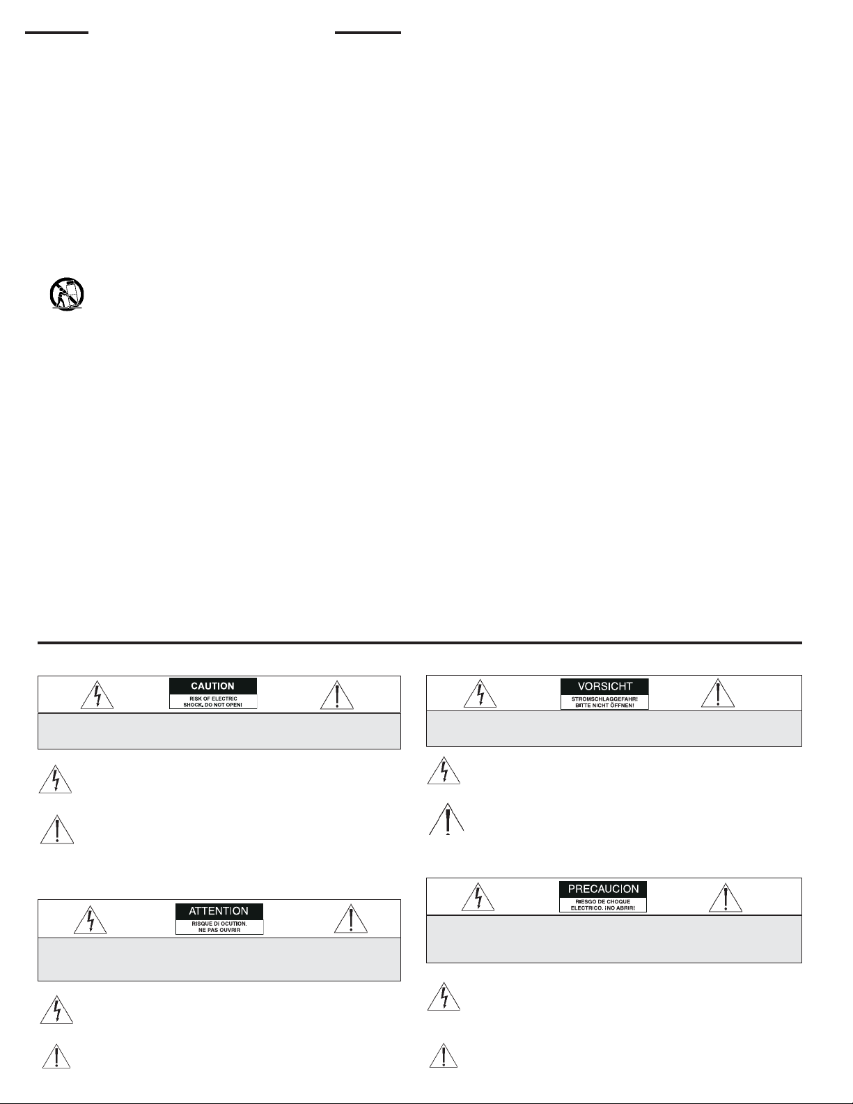
The lightning flash with an arrowhead symbol within an equilateral tri-
angle is intended to alert the user to the presence of uninsulated
"dangerous voltage" within the product's enclosure that may be of
sufficient magnitude to constitute a risk of electric shock to persons.
CAUTION: TO REDUCE RISK OF ELECTRICAL SHOCK, DO NOT OPEN COVERS. NO USER
SERVICEABLE PARTS INSIDE. REFER SERVICING TO QUALIFIED SERVICE PERSONNEL.
The exclamation point within an equilateral triangle is intended to
alert the user to presence of important operating and maintenance
(servicing) instructions in the literature accompanying the appliance.
SAFETY PRECAUTIONS:
This label may appear on the bottom of the unit due to space limitations.
L'éclair fléché dans un triangle équilatéral, avertit l'utilisateur de la
présence d'une "tension dangereuse" non isolée à l'intérieur de l'appareil
et d'une valeur suffisante pour constituer un risque d'électrocution.
Le point d'exclamation contenu dans un triangle équilatéral, avertit
l'utilisateur de la présence, dans la documentation qui accompagne
l'appareil, de consignes d'utilisation et de maintenance importantes.
SECURITE: En raison de limitation de place, cette étiquette peut être
placée sur le dessous de l'appareil.
DANGER: POUR ÉVITER TOUT RISQUE D'ÉLECTROCUTION, NE PAS OUVRIR LE BOÎTIER.
IL N'Y A PAS DE PIÈCES REMPLAÇABLES À L'INTÉRIEUR. POUR TOUTE RÉVISION,
S'ADRESSER À UN TECHNICIEN SPÉCIALISÉ.
VORSICHT: UM EINEN ELEKTRISCHEN SCHLAG ZU VERMEIDEN, ABDECKUNG NICHT
ENTFERNEN. WARTUNGEN ALLER ART QUALIFIZIERTEM PERSONAL ÜBERLASSEN.
PRECAUCION: PARA REDUCIR EL RIESGO DE CHOQUE ELÉCTRICO, FAVOR NO ABRIR LA
CUBIERTA. ESTE EQUIPO NO CONSTA DE PIEZAS O PARTES QUE REQUIEREN SERVICIO O
MANTENIMIENTO. PARA REPARACIONES FAVOR REFERIRSE A UN TÉCNICO CALIFICADO.
SICHERHEITSVORKEHRUNGEN: Aus Platzgründen kann diese Warnung
auf der Unterseite des Gerätes angebracht sein.
Das Blitzsymbol im gleichseitigen Dreieck soll den Benutzer auf nicht
isolierte "Hochspannung" im Gehäuse aufmerksam machen, die eventuell
stark genug ist, um einen elektrischen Schlag zu verursachen.
Das Ausrufezeichen im gleichseitigen Dreieck soll den Benutzer auf
wichtige Bedienungs- und Wartungsanleitungen in der dem Gerät beige-
fügten Literatur aufmerksam machen.
El símbolo representado por un relámpago con punta de flecha den-
tro de un triángulo equilátero, se muestra con el objetivo de alertar
al usuario que existen "voltages peligrosos" sin aislamiento, dentro de
la cubierta de la unidad. Dichos voltages pueden ser de tal magnitud
que constituyen un riesgo de choque eléctrico a personas.
El símbolo de exclamación dentro de un triángulo equilátero, se
muestra con el objetivo de alertar al ususario de que instrucciones
de operación y mantenimiento importantes acompañan al equipo.
PRECAUCIONES DE SEGURIDAD: Debido a limitaciones de espacio, esta
etiqueta puede aparecer en la parte inferior de la unidad.

3
CONTENTS
1 UNPACKING . . . . . . . . . . . . . . . . . . . . . . . . . . . . . . . . . . . . .3
2 ACCESSORIES . . . . . . . . . . . . . . . . . . . . . . . . . . . . . . . . . . . .3
2.1 Mounting Kits . . . . . . . . . . . . . . . . . . . . . . . . . . . . . . . . . . . . .3
3 SERVICE . . . . . . . . . . . . . . . . . . . . . . . . . . . . . . . . . . . . . . . . .3
4 CARE AND MAINTENANCE . . . . . . . . . . . . . . . . . . . . . . . .3
5 DESCRIPTION . . . . . . . . . . . . . . . . . . . . . . . . . . . . . . . . . . . .3
6 INSTALLATION . . . . . . . . . . . . . . . . . . . . . . . . . . . . . . . . . . .4
6.1 Maximum Camera/Lens Size . . . . . . . . . . . . . . . . . . . . . . . . .4
6.2 Tools Required . . . . . . . . . . . . . . . . . . . . . . . . . . . . . . . . . . . .4
6.3 Fixed Ceiling Installation . . . . . . . . . . . . . . . . . . . . . . . . . . . . .4
6.4 Suspended Ceiling Installation . . . . . . . . . . . . . . . . . . . . . . . .4
6.5 Tools Required . . . . . . . . . . . . . . . . . . . . . . . . . . . . . . . . . . . .4
6.6 Installation . . . . . . . . . . . . . . . . . . . . . . . . . . . . . . . . . . . . . . . .4
7 PARTS LIST . . . . . . . . . . . . . . . . . . . . . . . . . . . . . . . . . . . . . . .6
8 ACCESSORY PART LIST . . . . . . . . . . . . . . . . . . . . . . . . . . . .7
1UNPACKING
Unpack carefully. This is mechanical equipment and should be
handled with care.
Check for the following:
• Housing.
• Hardware Kit:
1 1/4-20 Thumb Screw.
2 Keys.
If an item appears to have been damaged in shipment, replace it
properly in its carton and notify the shipper. If any items are miss-
ing, notify Aigis Mechtronics.
The shipping carton is the safest container in which the unit may
be transported. Save it for possible future use.
2ACCESSORIES
2.1 Mounting Kits
Rotatable ceiling tile mounting kits are available for suspended-
ceiling installations; they are not included and must be ordered
separately.
HS9369
HS9069: Replaces a 2 ft x 2 ft ceiling tile.
HS9069M: Replaces a 600 mm x 600 mm ceiling tile.
HS9370
HS9070: Replaces a 2 ft x 2 ft ceiling tile.
HS9070M: Replaces a 600 mm x 600 mm ceiling tile.
3SERVICE
If the unit ever needs repair service or parts, the customer should
contact Aigis Mechtronics for authorization to return and shipping
instructions, 1-800-523-6500.
4CARE AND MAINTENANCE
There are no moving parts in this unit. Regularly scheduled main-
tenance will help prolong the operation life of this unit. Clean the
viewing window as needed with a mild, nonabrasive detergent in
water and a soft cloth.
5DESCRIPTION
The HS9369 and HS9370 are aesthetically designed indoor ceiling
housings for CCTV camera installations. These housings can be
easily mounted in fixed or suspended ceilings and are ideal for any
application where attractive and discreet CCTV monitoring is
required.
WARNING:
To prevent fire or shock hazards, do not expose
this unit or power supply to rain or moisture.

4
6 INSTALLATION
This installation should be made by qualified service
personnel and conform to the National Electrical Code
and applicable local codes.
6.1 Maximum Camera/Lens Size
HS9369: Accepts camera/lens combinations up to
330 L x 102 W x 102 H mm (13 x 4 x 4 in).
HS9370: Accepts camera/lens combinations up to
178 L x 76 W x 76 H mm (7 x 3 x 3 in).
6.2 Tools Required
Phillips screwdriver.
M10 (10 mm) Wrench or Socket.
6.3 Fixed Ceiling Installation
1. Determine the position of the unit in the ceiling and make the
appropriate cutout. Do not remove or damage any structural
members in the ceiling.
2. Unlock and open the cover. Remove any packing material
from the inside of the unit. See Figure 1.
3. Mark the mounting hole locations and drill any necessary
holes. Eight 7 mm (0.27) mounting holes are provided in the
backbox.
4. Decide how wiring will be routed into the housing. Remove
the appropriate conduit knockout(s). Two PG 13.5 (1/2 in)
knockouts are located in the front and two are located in the
back of the unit.
5. Remove the two 6 mm (0.25 in) knockouts from the top of the
backbox. These knockouts are for the attachment of a safety
support wire (not provided). The safety support wire must be
a solid steel wire with a minimum diameter of 2.7 mm (0.105
in) or 12 gauge wire.
Figure 1: HS9369 & 9370 Features and Parts
Camera Mounting System
Backbox
Knockouts (4X)
Faceplate
Lock
Cover
Mounting Holes
(8X)
6.4 Suspended Ceiling Installation
Accessory Mounting Kits Required (Not Included).
Ceiling tile mounting kits are for suspended-ceiling installations.
Each kit is constructed of 1 mm (0.04 in) aluminized steel with
an off-white semigloss polyurethane finish rotating through
360°.
HS9369
HS9069: Replaces a 2 ft x 2 ft ceiling tile.
HS9069M: Replaces a 600 mm x 600 mm ceiling tile.
HS9370
HS9070: Replaces a 2 ft x 2 ft ceiling tile.
HS9070M: Replaces a 600 mm x 600 mm ceiling tile.
Accessory Mounting Kits contain the following items:
Qty Part Description
1Rotating Plate
1Tile
3M3 x 4 Phillips Pan Head Screws
3M3 Fender Washer
8M5 x 12 Philips Pan Head Screws
4Mounting Feet
6.5 Tools Required
Phillips screwdriver
M10 (10 mm) Wrench or Socket
6.6 Installation
1. Unlock and open the cover. Remove any packing material from
the inside of the unit.
2. Decide how wiring will be routed into the housing. Remove
the appropriate conduit knockout(s). Two PG 13.5 (1/2 in)
knockouts are located in the front and two are located in the
back of the unit.
3. Remove the two 6 mm (0.25 in) knockouts from the top of the
backbox. These knockouts are for the attachment of a safety
support wire (not supplied). The safety support wire must be
a solid steel wire with a minimum diameter of 2.7 mm (0.105
in) or 12 gauge wire.
4. Attach the rubber mounting feet (provided) to each corner of
the backbox. See Figure 2.
6. Insert unit into ceiling and secure with eight fasteners (not
provided). Use fasteners rated for your specific ceiling mate-
rial where minimum pull out strength of each fastener should
be 150 N (35 lb). Attach the safety support wire
(not provided).
7. Attach the camera to the camera bracket using the 1/4-20
thumb screw provided in the hardware kit.
8. Make all necessary electrical connections.
9. Adjust the camera bracket position to the desired location and
tighten the two M6 hex bolts using an M10 (10 mm) wrench or
socket.
10. Close and lock the cover.

5
6. Slide the rotating plate over the backbox and on top of the
tile. Again, keep the painted side towards the cover.
See Figure 3.
7. Secure the M3 screws and washers onto the studs in the tile.
Make sure the washers overlap the rotating plate.
See Figure 4.
Figure 2: Mounting Feet Assembly
Figure 3: Assembling Mounting Kit
5. Position the tile through the backbox making sure the painted
side of the tile is towards the cover. See Figure 3.
Figure 4: Tile Assembly
8. Secure the HS9369 or HS9370 to the rotating plate by attach-
ing the six M5 screws through the mounting holes in the back-
box and into the rotating plate. Do not tighten at this time.
See Figure 5.
Figure 5: Securing the Unit to Mounting Kit
9. Position the unit into the ceiling opening. If ceiling opening is
larger than the tile, install additional "T" rails as necessary.
10. Rotate the HS9369 or HS9370 unit to the desired location and
tighten the M5 screws. Attach safety support wire.
11. Attach the camera to the camera bracket using the 1/4-20
screw provided in the hardware kit.
12. Make all necessary electrical connections.
13. Adjust the camera bracket position to the desired location and
tighten the two M6 hex bolts using an M10 (10 mm) wrench or
socket.
14. Close and lock the cover.
HS 9369 & 9370
Rubber Feet (4X)
Rotating Plate
Tile
HS 9369 & 9370
Rotating Plate
M5 x 12 Screws (8X)
Rotating Plate
M3 x 4 Screw (3X)
M3 Fender Washer
M3 Stud
Tile

6
7HS9369, HS9370 - PARTS LIST
HS9369
Part No.Qty. Part Description
315 2447 001 1 Camera Mount Assembly
315 2006 800 2 Screw, M6 x 16
315 2007 800 2 Washer, M6 Flat
315 2256 800 2 Washer, M6 Spiral Lock
315 2434 001 1 Mount,Top
315 2426 001 1 Cover
315 2433 001 1 Bracket,Adjustable Hook
315 2436 001 1 Lock, Single Bitted
315 2437 001 1 Washer, Steel (Lock)
315 2438 001 2 Hinge, Butt 1.5 x 1.5
315 2439 001 1 Faceplate, Clear 0.125 PC
315 2440 800 14 Rivet, 1/8-inch x 0.265
315 2431 001 1 Backbox
315 2452 002 1 Hardware Kit
315 3066 800 1 Thumb Screw, 1/4-20 x 5/16
HS9370
Part No.Qty. Part Description
315 2491 001 1 Camera Mount Assembly
315 2006 800 2 Screw, M6 x 16
315 2007 800 2 Washer, M6 Flat
315 2256 800 2 Washer, M6 Spiral Lock
315 2994 001 1 Mount,Top
315 2986 001 1 Cover
315 2433 001 1 Bracket,Adjustable Hook
315 2436 001 1 Lock, Single Bitted
315 2437 001 1 Washer, Steel (Lock)
315 2438 001 2 Hinge, Butt 1.5 x 1.5
315 2990 001 1 Faceplate, Clear 0.125 PC
315 2440 800 14 Rivet, 1/8-inch x 0.265
315 2992 001 1 Backbox
315 2452 002 1 Hardware Kit
315 3066 800 1 Thumb Screw, 1/4-20 x 5/16

7
8ACCESSORY PARTS LIST
HS9069
Part No.Qty. Part Description
315 2449 001 1 Tile Assembly HS9069
315 2450 001 1 Rotating Plate (Spinner)
315 2452 001 1 Kit, Hardware
315 1746 804 3 Screw, M3 x 4
315 2445 800 3 Washer, M3 Fender
315 2683 812 8 Screw, M5 x 12
315 2514-001 4 Rubber Feet
HS9069M
Part No.Qty. Part Description
315 2449 002 1 Tile Assembly HS9069M
315 2450 001 1 Rotating Plate (Spinner)
315 2452 001 1 Kit, Hardware
315 1746 804 3 Screw, M3 x 4
315 2445 800 3 Washer, M3 Fender
315 2683 812 8 Screw, M5 x 12
315 2514-001 4 Rubber Feet
HS9070
Part No.Qty. Part Description
315 3067 001 1 Tile Assembly HS9070
315 3068 001 1 Rotating Plate (Spinner)
315 2452 001 1 Kit, Hardware
315 1746 804 3 Screw, M3 x 4
315 2445 800 3 Washer, M3 Fender
315 2683 812 8 Screw, M5 x 12
315 2514-001 4 Rubber Feet
HS9070M
Part No.Qty. Part Description
315 3067 002 1 Tile Assembly HS9070
315 3068 001 1 Rotating Plate (Spinner)
315 2452 001 1 Kit, Hardware
315 1746 804 3 Screw, M3 x 4
315 2445 800 3 Washer, M3 Fender
315 2683 812 8 Screw, M5 x 12
315 2514-001 4 Rubber Feet

100 0029 001 AIG 10/02
Printed in U.S.A.
©2002 Aigis Mechtronics
1124 Louise Road,Winston-Salem, NC 27107-5450
Tel: 336.785.7740 Fax: 336.785.7744
Data subject to change without notice
This manual suits for next models
5
Table of contents
Other Aigis Mechtronics Camera Accessories manuals

Aigis Mechtronics
Aigis Mechtronics HS9385SS User manual

Aigis Mechtronics
Aigis Mechtronics HS9349 SERIES User manual

Aigis Mechtronics
Aigis Mechtronics HS9383S-2HP User manual

Aigis Mechtronics
Aigis Mechtronics HS9386SS User manual

Aigis Mechtronics
Aigis Mechtronics HS9405 Series User manual

Aigis Mechtronics
Aigis Mechtronics HS948 Series User manual

Aigis Mechtronics
Aigis Mechtronics MLAC Series User manual

Aigis Mechtronics
Aigis Mechtronics HS9386 Series User manual

Aigis Mechtronics
Aigis Mechtronics HS9305 Series User manual

Aigis Mechtronics
Aigis Mechtronics HS9383S Series User manual