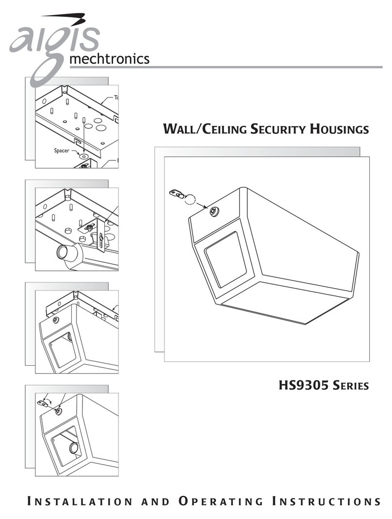
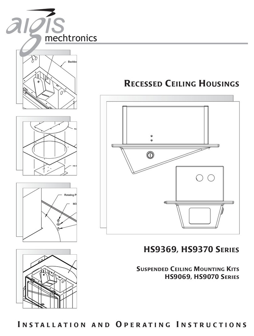
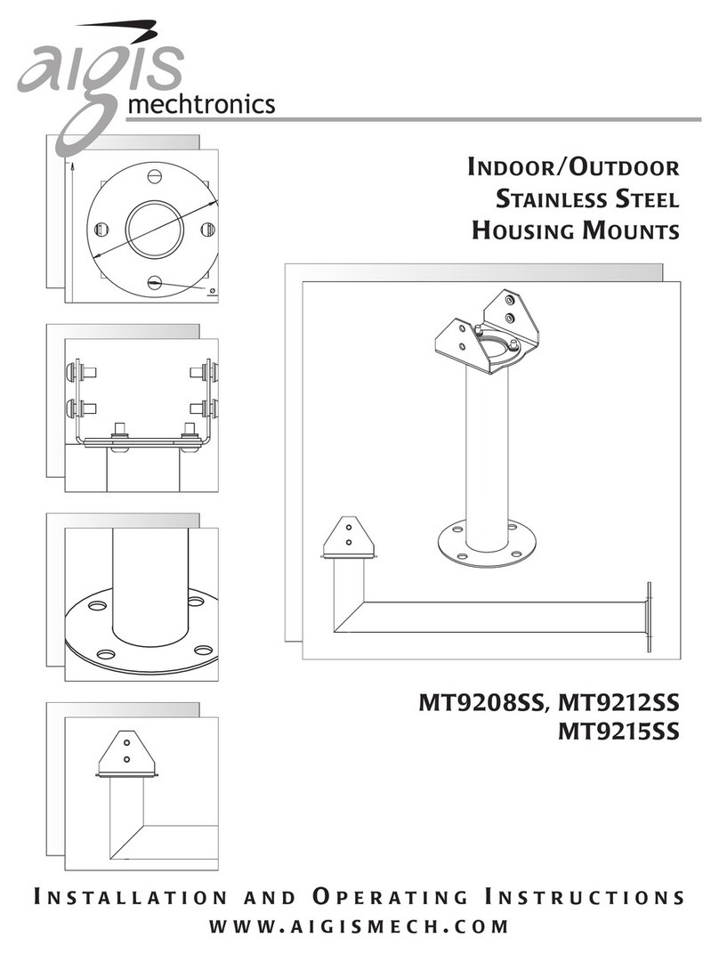
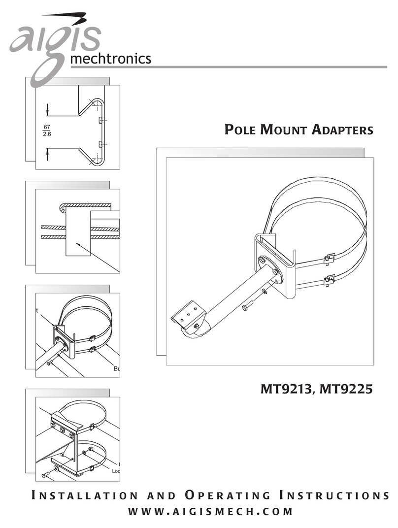
Aigis Mechtronics HS9383S-2HP User manual

Stainless Steel
Pressurized Housing
HS9383S-2HP
HS9383S-P
INSTALLATION AND OPERATING INSTRUCTIONS
WWW.AIGISMECH.COM

2
IMPORTANT SAFEGUARDS
1. Read Instructions - All the safety and operating
instructions should be read before the unit is operated.
2. Retain Instructions - The safety and operating instructions
should be retained for future reference.
3. Heed Warnings - All warnings on the unit and in the
operating instructions should be adhered to.
4. Follow Instructions - All operating and use instructions
should be followed.
5. Cleaning - Unplug the unit from the outlet before
cleaning. Do not use liquid cleaners or aerosol cleaners.
Use a damp cloth for cleaning.
6. Attachments - Do not use attachments not
recommended by the product manufacturer as they may
cause hazards.
7. Accessories - Do not place this unit on an unstable stand,
tripod, bracket, or mount. The unit may fall, causing
serious injury to a person and serious damage to the unit.
Use only with a stand, tripod, bracket, or mount
recommended by the manufacturer, or sold with the
product. Any mounting of the unit should follow the
manufacturer's instructions, and should use a mounting
accessory recommended by the manufacturer.
An appliance and cart combination should be moved
with care. Quick stops, excessive force, and uneven
surfaces may cause the appliance and cart combination
to overturn.
8. Ventilation - Openings in the enclosure, if any, are
provided for ventilation and to ensure reliable operation
of the unit and to protect it from overheating. These
openings must not be blocked or covered. This unit
should not be placed in a built-in installation unless proper
ventilation is provided or the manufacturer's instructions
have been adhered to.
9. Power Sources - This unit should be operated only from
the type of power source indicated on the marking label.
If you are not sure of the type of power supply you plan
to use, consult your appliance dealer or local power
company. For units intended to operate from battery
power, or other sources, refer to the operating
instructions.
10. Grounding or Polarization - This unit may be equipped
with a polarized alternating-current line plug (a plug
having one blade wider than the other). This plug will fit
into the power outlet only one way. This is a safety
feature. If you are unable to insert the plug fully into the
outlet, try reversing the plug. If the plug should still fail to
fit, contact your electrician to replace your obsolete
outlet. Do not defeat the safety purpose of the polarized
plug.
Alternately, this unit may be equipped with a 3-wire
grounding-type plug, a plug having a third (grounding) pin.
This plug will only fit into a grounding-type power outlet.
This is a safety feature. If you are unable to insert the plug
into the outlet, contact your electrician to replace your
obsolete outlet. Do not defeat the safety purpose of the
grounding-type plug.
11. Power-Cord Protection - Power-supply cords should be
routed so that they are not likely to be walked on or
pinched by items placed upon or against them, paying
particular attention to cords and plugs, convenience
receptacles, and the point where they exit from the
appliance.
12. Power Lines - An outdoor system should not be located
inthe vicinity of overhead power lines or other electric
light or power circuits, or where it can fall into such
power lines or circuits. When installing an outdoor
system, extreme care should be taken to keep from
touching such power lines or circuits as contact with
them might be fatal. U.S.A. models only - refer to the
National Electrical Code Article 820 regarding installation
of CATV systems.
13. Overloading - Do not overload outlets and extension
cords as this can result in a risk of fire or electric shock.
14. Object and Liquid Entry - Never push objects of any kind
into this unit through openings as they may touch
dangerous voltage points or short-out parts that could
result in a fire or electric shock. Never spill liquid of any
kind on the unit.
15. Servicing - Do not attempt to service this unit yourself as
opening or removing covers may expose you to
dangerous voltage or other hazards. Refer all servicing to
qualified service personnel.
16. Damage Requiring Service - Unplug the unit from the
outlet and refer servicing to qualified service personnel
under the following conditions:
a. When the power-supply cord or plug is damaged.
b. If liquid has been spilled, or objects have fallen into
the unit.
c. If the unit has been exposed to rain or water.
d. If the unit does not operate normally by following the
operating instructions. Adjust only those controls
that are covered by the operating instructions, as an
improper adjustment of other controls may result in
damage and will often require extensive work by a
qualified technician to restore the unit to its normal
operation.
e. If the unit has been dropped or the cabinet has been
damaged.
f. When the unit exhibits a distinct change in
performance--this indicates a need for service.
17. Replacement Parts - When replacement parts are
required, be sure the service technician has used
replacement parts specified by the manufacturer or have
the same characteristics as the original part.
Unauthorized substitutions may result in fire, electric
shock or other hazards.
18. Safety Check - Upon completion of any service or repairs
to this unit, ask the service technician to perform safety
checks to determine that the unit is in proper operating
condition.
19. Coax Grounding - If an outside cable system is connected
to the unit, be sure the cable system is grounded. U.S.A.
models only--Section 810 of the National Electrical Code,
ANSI/NFPA No.70-1981, provides information with
respect to proper grounding of the mount and supporting
structure, grounding of the coax to a discharge unit, size
of grounding conductors, location of discharge unit,
connection to grounding electrodes, and requirements
for the grounding electrode.
20. Lightning - For added protection of this unit during a
lightning storm, or when it is left unattended and unused
for long periods of time, unplug it from the wall outlet
and disconnect the cable system. This will prevent
damage to the unit due to lightning and power-line
surges.
This label may appear on the bottom of the unit due to
space limitations.
The lightning flash with an arrowhead symbol
within an equilateral triangle is intended to alert
the user to the presence of uninsulated
"dangerous voltage" within the product's
enclosure that may be of sufficient magnitude to
constitute a risk of electric shock to persons.
The exclamation point within an equilateral
triangle is intended to alert the user to presence
of important operating and maintenance
(servicing) instructions in the literature
accompanying the appliance.
CAUTION: TO REDUCE THE RISK OF ELECTRICAL
SHOCK, DO NOT OPEN COVERS. NO USER
SERVICEABLE PARTS INSIDE. REFER SERVICING TO
QUALIFIED SERVICE PERSONNEL.
3
SAFETY PRECAUTIONS
FCC & ICES INFORMATION
(U.S.A. and Canadian Models Only)
WARNING -This equipment has been tested and found to comply with the limits for a Class B digital device,
pursuant to Part 15 of the FCC Rules and ICES-003 of Industry Canada. These limits are designed to provide
reasonable protection against harmful interference when the equipment is operated in a residential installation. This
equipment generates, uses and can radiate radio frequency energy and, if not installed and used in accordance with the
instructions, may cause harmful interference to radio communications. However, there is no guarantee that
interference will not occur in a particular installation. If this equipment does cause harmful interference to radio or
television reception, which can be determined by turning the equipment off and on, the user is encouraged to try to
correct the interference by one or more of the following measures:
-Reorient or relocate the receiving antenna.
-Increase the separation between the equipment and receiver.
-Connect the equipment into an outlet on a circuit different from that
to which the receiver is connected.
-Consult the dealer or an experienced radio/TV technician for help.
Intentional or unintentional changes or modifications not expressly approved by the party responsible for
compliance shall not be made. Any such changes or modifications could void the user's authority to operate the
equipment.
The user may find the following booklet prepared by the Federal Communications Commission helpful: "How to
Identify and Resolve Radio-TV Interference Problems". This booklet is available from the
U.S. Government Printing Office, Washington, DC 20402, Stock
No. 004-000-00345-4.

4
2 SERVICE
If the unit ever needs repair service, the customer should contact Aigis Mechtronics for return authorization
and shipping instructions.
3 CARE AND MAINTENANCE
There are no moving parts in this unit. Regularly scheduled maintenance will help prolong the operation life of
this unit. Clean the viewing window as needed with a mild, nonabrasive detergent in water and a soft cloth.
4DESCRIPTION
The HS9383S-2HP and the HS9383S-P are pressurized stainless steel enclosures designed for CCD camera
installations.
ENVIRONMENTAL ENCLOSURE
Construction
This stainless steel housing is a self contained unit with a single corrosion resistant connector for power, video,
lens control, and external sync. The camera housing is sealed at both ends by radial pressure "O" rings to
create a tight seal; front-to-back motion is prevented by a retaining ring in the front and in the back. Chemically
strengthened glass is used for the faceplate for maximum strength and safety.
The housing is fitted with a standard Schrader valve to allow pressurization with dry nitrogen to 35 kPa (5 lb
PSIG) nominal at one atmosphere. An overpressurization safety relief valve is mounted on the rear cap along
with the Schrader valve. The purpose of the relief valve is to provide a safety pressure blow-off should internal
pressure exceed 140 kPa (20 PSIG) at one atmosphere. A pressurization warning label is visible on the back
of housing.
1 UNPACKING
Unpack carefully. This is electromechanical equipment and should be handled with care.
If an item appears to have been damaged in shipment, replace it properly in its carton and notify the shipper. If
any items are missing, notify Aigis Mechtronics, LLC Sales Representative or Customer Service. The shipping
carton is the safest container in which the unit may be transported. Save it for possible future use. Verify that
the parts listed as follows have been included.
Hardware Kit
Quantity Part Description
3 Cable Ties
2 1/4-20 x 1/4-inch Button Head Cap Screw
2 1/4-20 x 3/8-inch Button Head Cap Screw
2 1/4-20 x 1/2-inch Button Head Cap Screw
1 1/4-20 x 5/8-inch Button Head Cap Screw
1 1/4-20 x 3/4-inch Button Head Cap Screw
1 0.4 mm (0.016 in) Plastic Spacer
1 1.7 mm (0.065 in) Plastic Spacer
1 3.9 mm (0.154 in) Plastic Spacer
1 7.4 mm (0.292 in) Plastic Spacer
1 9.7 mm (0.385 in) Plastic Spacer
2 5/16 Flat Washers
2 1/4 Lock Washer
1 Bit Driver 5/32
Quantity Part Description
1 Rear Connection Coupler
1 16 Pin Wire Harness Plug
1 Seal Sleeve

5
5 INSTALLATION
CAUTION
This installation should be made by qualified service personnel and conform to all local codes.
5.1 Model Designation
Model
No. Rated Input Range
HS9383S-2HP* 24VAC 21.6 to 26.6
50/60 Hz
HS9383S-P N/A N/A
*Power Requirements: Heater requires 10 watts.
Do Not Exceed 30 VAC Input on 24 VAC models. Operation above 30 VAC violates low voltage operation (Class
2Specifications). Normal operation is 24 VAC.
5.2 Tools Required
Min. 3/16 x 4-inch Flat blade screwdriver
5/32-inch (or 4 mm) hex wrench
Wire Stripper/Crimper Tool
5.3 Cradle Removal
Figure 1: Remove Retaining Ring
Use a Flatblade
Screwdriver
1. Remove the cradle from the housing by first removing the rear retaining ring from the rear cap. Place a Flat blade
screwdriver underneath the relieved portion of the retaining ring and gently pry it outward. See Figure 1.
2. Remove the cradle from the housing by applying pressure to the front cap to push the cradle through the housing
CCAAUUTTIIOONN::
DDOONNOOTTpush on the glass window.
Apply pressure to the font cap only.

6
Figure 2: Camera and Lens Installation
Figure 3: Rear Connector Figure 4: Mating Connector Coupler Installed
5.4 Camera/Lens Installation
Spacer
Washer
1/4 - 20 Screw
With the cradle removed from the housing, follow all of the steps below for the lens type to be installed.
1. Place the camera/lens combination into the cradle assembly.
2. Fixed Lens Cameras: Position the camera/lens 1 mm (0.04 in) away from the faceplate. The camera/lens are secured to
the cradle with 1/4-20 button head cap screw (BHCS), with a combination of nylon spacers and washers to align the lens
in the center of the viewing window.
3.Zoom Lens Cameras: Allow 3/16-inch (5 mm) clearance from the front face of the lens to the front faceplate of the cradle
during the camera/lens assembly. This clearance provides the necessary space for the lens to extend outward when zooming.
Secure both the camera and the lens to the cradle with the 1⁄4-20 BHCS and appropriate plastic spacer.
4. Connect the camera into the housing.
5. Attach camera power source.
6. Connect BNC cable
7. After servicing, slide the cradle back into the housing and replace the the rear retaining ring by inserting it into the
housing groove. This secures the cradle assembly in the housing.
5.5 Power and Video Connections
All electrical connections are made via the single corrosion-resistant connector on the rear panel. Fig. 3.
A mating connector coupler and crimp pins are supplied. Fig. 4.
The pins will accept wire from a minimum of 0.5 mm2 (20 AWG) to a maximum of 1.5 mm2 (16 AWG).
Crimp the wire to the connector using an appropriate crimp tool.
See Section 5.6 Making the Wiring Harness for instrutions on making the wiring harness with the mating coupler.
Information on sync and video hookups is given in the basic camera instructions. Zoom lens models require a zoom lens
control system.

(Wire Side)
Bulkhead MS3114E20-16P (Male)
Mate MS3126F20-16S (Female)
(AIGIS #315 1592-001)
(Wire Side)
Bulkhead MS3114E20-16P (Male)
Mate MS3126F20-16S (Female)
(AIGIS #315 1592-001)
A
B
C
D
E
F
G
H
J
K
L
M
N
P
R
S
A NC
B NC
C NC
D NC
E NC
F Video Shield
G Video Output
H NC
J NC
K AC Neutral
L AC Hot
M NC
N NC
P NC
R NC
S NC
Wiring Diagram
13
(Wire Side)
Bulkhead MS3114E20-16P (Male)
(Aigis # 315 1591 001)
Mate MS3126F20-16S (Female)
(Aigis #315 1592-001)
A
B
C
D
E
F
G
H
J
K
L
M
N
P
R
S
Bulkhead MS3114E20-16P (Male)
(Aigis # 315 1591 001)
Mate MS3126F20-16S (Female)
(Aigis #315 1592-001)
(Wire Side)
AZoom
B Focus
CCommon
D NC
E NC
F Video Shield
G Video Output
H ADI Option
J NC
KAC Neutral
L AC Hot
M NC
N NC
PNC
R NC
S NC
Zoom Lens Models
7
5.6 Making the Wire Harness
1. Feed the power and video wires through the back of the connection coupler.
2. Slide on the white seal sleeve onto the wires.
3. Strip the wire using the manufacture’s specs to crimp and pin out the wires into the wire harness plug. See the wiring
diagram below.
4. Slide the white seal sleeve down against the back of the the wire harness plug.
5. Apply electrical tape around the plug and the seal sleeve to create a form to pour the potting compound into.
6. Using potting compound fill the electrical tape form about 1/2” thick.
7. Let the potting compound dry before removing the electrical tape to ensure a tight seal.
Figure 5: Wiring Diagram
Tools For Use
With Connectors
The following tools are available from:
Daniels Manufacturing Corporation
6103 Anno Avenue
Orlando, FL 32809
407-855-6161
Crimp Tool: AF8 (M22520/1-01).
Crimp Tool Turret: TH1A (M22520/1-02).
Insertion Tool: MS24256A16.
Removal Tool: MS24256R16.
The following tools are available from:
Amphenol Corp.
40-60 Delaware Ave.
Sidney, NY 13838-1395
607-563-5011
Insertion Tool: M81969/17-04.
Removal Tool: M81969/19-08.
Connection
Coupler
Slide Seal Sleeve after
pinning wires
Apply potting
compound
Apply
Electrical
Tape
Power & Video Wires
Wire
Harness
Plug
Tighten BHC SS Screws-x3
Seal Sleeve
1
2
17
4
15
16
13
Strip the wire
crimp and pin
out the wires. Let dry

8
5.7 Connecting the Wire Harness to the Housing
1. After completing the wiring harness, make sure the O-Ring is in place at the bottom of the threads on the rear cap of the
housing.
2. Insert the wire harness plug into the back of the housing.
12
13
14
15 16
11
12
13
14
15 16
11
12
13
14
15 16
11
3. Slide down and screw on the connection coupler until it is resting on the rear cap.
Connect Coupler
O-Ring

9
12
13
14
15 16
11
4. In a chris-cross pattern using the 5/32-inch hex wrench, tighten down the three BHC SS screws in the back of the coupler.
Tighten all
three screws

10
5.9 Mounting
Prepare and secure the mount to the wall or mounting surface as described below.
1. Determine a secure mounting location.
2. Cautions:
a. For a secure installation, use four 8-mm (5/16-in) diameter fasteners (not included). Use stainless steel or zinc plated
fasteners.
b. If bolts are used, they should extend through the mounting surface and be secured with flat washers, lock washers,
and nuts on the opposite side. Each bolt must have a minimum pull-out strength of 200 kg (450 lb).
c. If studs are used, they should be anchored in concrete or welded to a steel backer plate. Each stud must have a
minimum pull out strength of 200 kg (450 lb).
c. If studs are used, they should be anchored in concrete or welded to a steel backer plate. Each stud must have a
minimum pull out strength of 200 kg (450 lb).
d. If the wall mount is attached to wood or to a blind structure (with no access to the rear), each fastener must have a
minimum pull-out strength of at least 200 kg (450 lb).
3. Locate the four holes or stud locations using the flange as a template (four holes equally spaced on a 69.9-mm (2-3/4-in
bolt circle).
4. Install the mount using bolts or studs at least 8-mm (5/16-in) in diameter.
5. Turn the housing into position and lock the mounting head in by using the supplied 1/8” long-arm hex wrench to tighten
screws. For more information see the MT9208SS & MT9212SS Stainless Steel Mount Instruction Booklet.
5.8 Pressurization
1. The housing is fitted with a standard Schrader valve to allow pressurization with dry nitrogen to 35 kPa (5 lb PSIG)
nominal at one atmosphere.
Using the Schrader Valve add 10psi nitrogen to pressurize the housing.
2. An overpressurization safety relief valve is mounted on the rear cap along with the Schrader valve. The purpose of the
relief valve is to provide a safety pressure blow-off should internal pressure exceed 140 kPa (20 PSIG) at one atmosphere.
Figure 3: Rear Cap Valves
CAUTION
PRESSURIZED CONTAINER.
DO NOT open the housing unit until pressure is removed.
DO NOT exceed 70kPa (10 PSIG) at one atmosphere.
Schrader Valve
Over pressure
safety relief valve

11
mm
in
350,2
13.79
203,2
8.00
302,6
11.91
3.75
95,3
88,9
3.50
8,9
.35
ø
ø
ø
mm
in
304,8
12.0
14.00
5.832
71,9
355,6
6. DIMENSIONAL OUTLINES

©2005 Aigis Mechtronics
1124 Louise Road Winston-Salem, NC 27107-5450
Tel: 336.785.7740 Fax: 336.785.7744
Data subject to change without notice.
100 0193 001 AIG 02/07
Draft Printed in U.S.A.
This manual suits for next models
1
Table of contents
Other Aigis Mechtronics Camera Accessories manuals

Aigis Mechtronics
Aigis Mechtronics MT9208SS User manual

Aigis Mechtronics
Aigis Mechtronics HS9369 Series User manual

Aigis Mechtronics
Aigis Mechtronics HS9386 Series User manual

Aigis Mechtronics
Aigis Mechtronics HS9385SS User manual

Aigis Mechtronics
Aigis Mechtronics MT9213 User manual

Aigis Mechtronics
Aigis Mechtronics HS948 Series User manual

Aigis Mechtronics
Aigis Mechtronics HS9349 SERIES User manual

Aigis Mechtronics
Aigis Mechtronics HS9405 Series User manual

Aigis Mechtronics
Aigis Mechtronics HS9386SS User manual

Aigis Mechtronics
Aigis Mechtronics PT9420-2PSL User manual