AIM Joraco TOGGLE-AIRE 2530 Series Installation and operating instructions

“The Pneumatic Toggle Press Innovators”.®Since 1947.
AUTOMATED INDUSTRIAL MACHINE,INC
TOGGLE-AIRE®DIVISION
347 Farnum Pike
Smithfield, RI, USA 02917
401-232-1710
www.joraco.com
Installation, Operation and Maintenance
10 & 16 Ton, 2530 & 3530 Series Bench Presses

IMPORTANT
It is the responsibility of the employer/purchaser
to provide his or her employees with proper point
of operation guards, and to ensure that this
equipment is used in accordance with the
manufacturer's recommendations as well as any
OSHA, federal, or state regulations that are
applicable to such equipment. Because it is
impossible to anticipate the conditions under
which our equipment will be operated, additional
safety devices and methods may be required to
insure operator safety. Besides conforming to all
federal, state, and local codes, the buyer should
consider the safety of the entire operation
involving any press, and see that any additional
guarding, training, and maintenance deemed
necessary is developed and enforced to protect
the wellbeing of the operator.
THINK SAFETY . . .
. .WORK SAFELY
COPYRIGHT 2018
by
AUTOMATED INDUSTRIAL MACHINE, INC.
Smithfield, RI, USA
All rights reserved

TOGGLE-AIRE MODEL 2530 & 3530 SERIES PRESSES
INSTALLATION, OPERATION, AND MAINTENANCE
-1-
Section I: Installation
1. Carefully remove the press from the crate,
taking note of separately packed items such
as the "Quick Exhaust Unit", "Synchro-Sig" Two
Hand Actuator or any other accessories you
may have ordered.
2. Attach "Quick Exhaust Unit"
(See photos 1.1 and 1.2)
a. Screw brass nipple into top port of
the
main cylinder located at the rear of
the press. Once tight, orient the
assembly as shown in photo 1.2.
b. Locate the poly-flo tubing that runs
from the main valve assembly on the
right side of the press. Connect this
tube to the elbow in the inlet port of
the "Quick Exhaust Unit".
3. Attach "Synchro-Sig" Actuator.
(See photos 1.3 and 1.4)
A. Locate the 1/4" yellow tubing found
under the press platen. Connect the
tubing to the appropriate fittings on
the actuator. See markings on the
tubing. DO NOT OVERTIGHTEN.
Normally, 1/2 turn past finger tight is
sufficient for an airtight connection.
B. Using the 1/4-20 hex head bolts
supplied, mount the "Synchro-Sig" to
the press as shown.
NOTE: To ensure operator safety some
applications may require that you
locate the "Synchro-Sig" actuator
further away from your tooling.
Photo 1.1
Photo 1.2
Photo 1.3
Photo 1.4

TOGGLE-AIRE MODEL 2530 & 3530 SERIES PRESSES
INSTALLATION, OPERATION, AND MAINTENANCE
-2-
4. Mount the press to your stand or workbench
(See photo 1.5)
A. Select a bench of suitable size and
strength.
B. Bolt the press to the bench using the
holes located in the feet of the press
frame below the platen area. DO NOT
operate the press unless it is securely
mounted on a bench or stand.
CAUTION: WHENEVER CONNECTING YOUR AIR
SUPPLY TO THE PRESS BE CERTAIN TO
FOLLOW SAFE OPERATING
PROCEDURES AND KEEP ALL PARTS
OF YOUR BODY AWAY FROM THE
MOVING PARTS OF THE PRESS!
5. Connect air supply
(See photos 1.6, 1.7, 1.8)
A. The air supply must be clean and
conditioned. Preferably, a Filter,
Regulator, Lubricator Unit, (Joraco
Part No. FRL-2530) should be located
within 6 feet of the press. For
optimum results all air lines, fittings,
and hoses used to supply the press
should be the equivalent of 1/2" NPT
minimum.
B. The minimum air pressure for
operation is 50 PSI. The maximum is
125 PSI. The optimum operating range
is 80 to 100 PSI. If your application
consistently requires substantially
more than 100 PSI it may indicate the
need for a stronger press.
C. Connect the air supply to the press at
the inlet port on Part No. G-2530, 3-
way, On-Off Valve (photo 1.7 & 1.8).
NOTE: A three way Shut Off Valve like the
one supplied must always be used to
insure complete bleeding of the press
circuits when air supply is off.
Photo 1.5
Photo 1.6
Photo 1.7
Photo 1.8

TOGGLE-AIRE MODEL 2530 & 3530 SERIES PRESSES
INSTALLATION, OPERATION, AND MAINTENANCE
-3-
6. Turn on air supply
(See photos 1.9, 1.10)
A. Remove the yellow lock out device
found on the On-Off Valve (photo 1.9).
To turn the air on simply move the gold
colored sleeve downward until it stops.
Slide the sleeve upward to the stop to
shut the supply off. With the supply
on, check for air leaks and be sure all
connections you have made are secure
and air tight. If air leaks from inside
the "Synchro-Sig" actuator, then the
connections are incorrect. Correctly
reconnect the tubing, taking note of
the tubing labels.
NOTE: When the press is not in use, being
serviced or maintained, always SHUT
OFF the air supply and replace the
lockout device. Secure with a
padlock, etc. to prevent
unauthorized use of the press.
CAUTION: BEFORE PROCEEDING, CLEAR THE
PRESS TABLE AND WORK AREA OF ALL
TOOLS, FOREIGN OBJECTS, AND
BODY PARTS.
7. Test the installation
(See photos 1.11, 1.12)
A. Test the "Synchro-Sig" Two Hand
Actuator by simultaneously depressing
the buttons on the Model SS-PB or by
simultaneously placing a finger in each
sensing "button" on the Model SS-OT. If
the buttons are continuously held
down the press should cycle once,
return to the top of stroke and await
another signal from the actuator (CSR
G2 mode only).
NOTE: If press does not return to top of stroke
when buttons are continuously held
down then depth must be adjusted
(See pg. 6)
Photo 1.9
Photo 1.10
Photo 1.11
Photo 1.12

TOGGLE-AIRE MODEL 2530 & 3530 SERIES PRESSES
INSTALLATION, OPERATION, AND MAINTENANCE
-4-
(See photos 1.13, 1.14, 1.15, 1.16)
B. Test the "Set-Up" Valve.
The press is equipped with a "Set-Up"
valve which allows tool setters or
maintenance personnel to lock the ram
in the down position to facilitate tool
depth adjustment. Check the function
of this valve. To actuate this valve,
back out the red locking screw from
the valve guard (photo 1.14). Move the
valve lever to the down position (photo
1.15). The press ram will immediately
descend to the bottom of the stroke
and stay in that position. Once the
ram depth has been set, (see Section
II, Paragraph 2) return the valve lever
to the up position (photo 1.16). The
ram will immediately return to the top
of the stroke.
NOTE: After using the "Set-Up" valve, always
lock the valve in the up position using
the red locking screw.
CAUTION: THIS VALVE IS NOT DESIGNED FOR
USE IN PRODUCTION AND SHOULD
ONLY BE USED BY AUTHORIZED AND
QUALIFIED PERSONNEL
Photo 1.13
Photo 1.14
Photo 1.15
Photo 1.16

TOGGLE-AIRE MODEL 2530 & 3530 SERIES PRESSES
INSTALLATION, OPERATION, AND MAINTENANCE
-5-
(See photo 1.17)
C. Optional Auxiliary Ram Up Valve
(On BEM control systems only)
2530 & 3530 BEM presses are equipped
with an Auxiliary Ram Up Valve. It is
used to manually reverse the press ram
to the up position during set up
procedures or in the case of misloaded
parts, ram set too deep, etc., all
conditions which do not allow the press
to "toggle" out and stall the press prior
to completion of the stroke. See
Section II, paragraphs 2 and 3 for
additional information on the use of
the Auxiliary Ram Up Valve.
(See photo 1.18)
D. Ram Speed Adjustment.
(Optional on 2530 & 3530 Series
Presses)
The ram speed on the down stroke can
be adjusted to suit your
application.
Locate the adjustable flo-contol
muffler. Unlock the adjusting screw
and screw it in to slow the ram down,
back it out to increase ram speed.
Lock the adj. screw when speed has
been set.
NOTE: When operating the press with slow
ram speed, special guarding and
control considerations apply.
Photo 1.17
Photo 1.18

TOGGLE-AIRE MODEL 2530 & 3530 SERIES PRESSES
INSTALLATION, OPERATION, AND MAINTENANCE
-6-
Section II: Set Up and Operation
(See photos 2.1, 2.2)
NOTE: Prior to installing any tooling in the
press, proper point of operation
guarding, specifically designed for
your tooling, must be built and
mounted on or around your tooling.
CAUTION: NEVER OPERATE, SERVICE, OR
ADJUST THIS MACHINE WITHOUT
PROPER INSTRUCTION.
NEVER SERVICE THIS MACHINE
WITHOUT FIRST SHUTTING OFF AIR
SUPPLY.
NEVER OPERATE THIS MACHINE WITH
SAFETY GUARDS REMOVED.
1. Mount your tooling
(See photos 2.3, 2.4)
A. Using the tapped holes in the press
platen (photo 2.3), mount the lower
portion of your tooling to the press.
The platen is machinable and can be
drilled and tapped as necessary. The
standard bore in the press ram is .8125"
with a depth of 1.5". Precisely fit your
shank to the bore of the ram and lock
the shank in with the 5/16-18
hardened lock screw located on the
face of the ram. The end of the ram
should bear against the upper portion
of your tooling.
NOTE: If your tool incorporates guide pins,
etc. be sure the tooling easily moves
along the full length of travel with no
binding or misalignment. Correct any
problems found in the tool before
placing tooling into production.
Photo 2.1
Photo 2.2
Photo 2.3
Photo 2.4

TOGGLE-AIRE MODEL 2530 & 3530 SERIES PRESSES
INSTALLATION, OPERATION, AND MAINTENANCE
-7-
2. Adjust the depth setting (end of stroke)
(See photos 2.5, 2.6, 2.7, 2.8, 2.9)
A. Use "Set-Up" valve to bring the ram
to bottom of stroke under power. (See
Section I, Paragraph 7B)
1. Use the regulator component in
your Filter, Regulator, Lubricator
unit to adjust the line pressure
to approx. 40 PSI.
(NOTE: The minimum OPERATING
pressure during actual production
runs should always be 50 PSI). For
Set-Up purposes, however, it is
acceptable to use lower line
pressures.
B. Alternatively, the ram can be lowered
manually to allow for alignment of
tooling, etc. To lower the ram
manually:
1. SHUT OFF AIR SUPPLY.
2. Remove the top guard.
3. Lower ram by placing appropriate
steel bar between the ram yoke
(JP-710) and the pivot of the lever
(JO-110).
4. Pull the bar towards the front of
the press to lower the ram.
CAUTION: RAM WILL RETURN UP WHEN AIR
SUPPLY IS RESTORED.
C. Adjust the final depth of the press by
loosening the Lock Nut (JP-3310) on
the Ram Adjusting Screw (JP-1110)
located at the top of the press.
1. Rotate the screw up or down to the
desired position. Remember, if
your press has the Standard Ram
Adjustment Screw, one revolution
of the screw is .071" of
adjustment.
Photo 2.5
Photo 2.6
Photo 2.7
Photo 2.8

TOGGLE-AIRE MODEL 2530 & 3530 SERIES PRESSES
INSTALLATION, OPERATION, AND MAINTENANCE
-8-
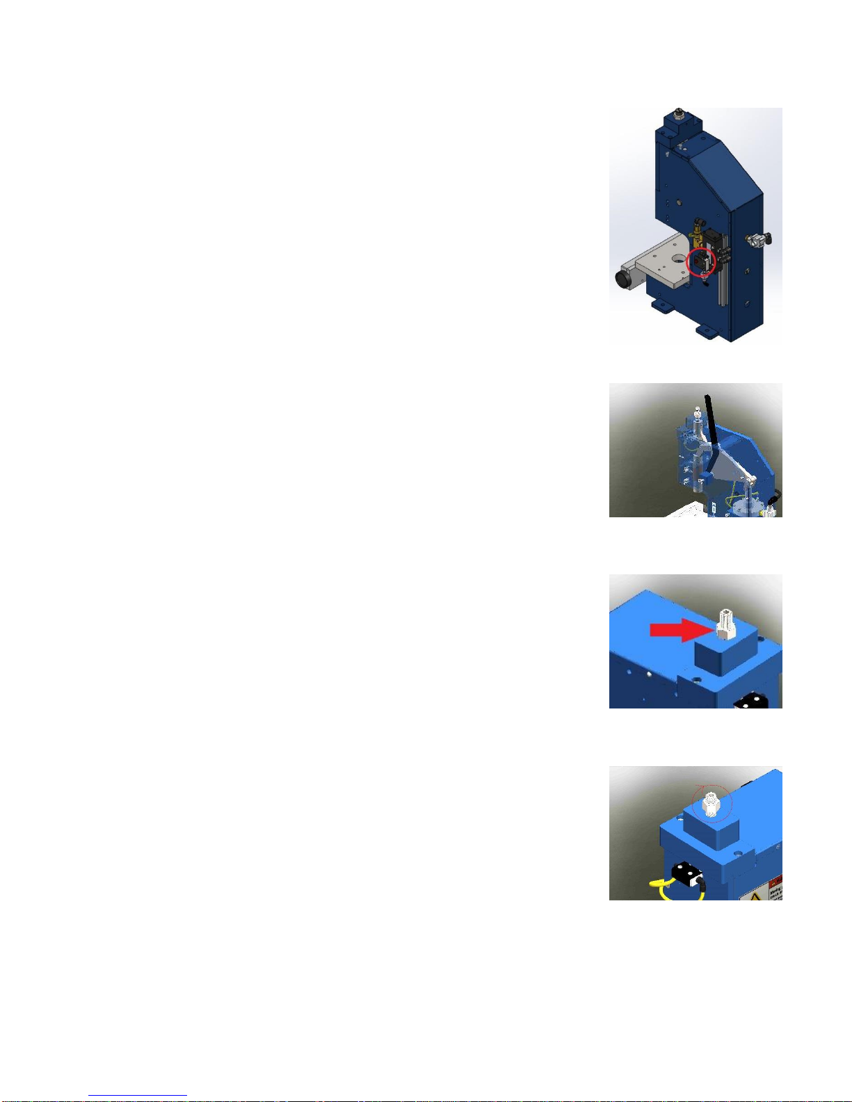
NOTE: In some cases, with the ram is in
the down position and the air is
on, it may not be possible to
adjust the ram up. To adjust up,
shut off air supply before
adjusting.
2. Final adjustments should always
be made by screwing the ram down
to the desired point.
3. Lock the ram adjusting screw in
place with the lock nut.
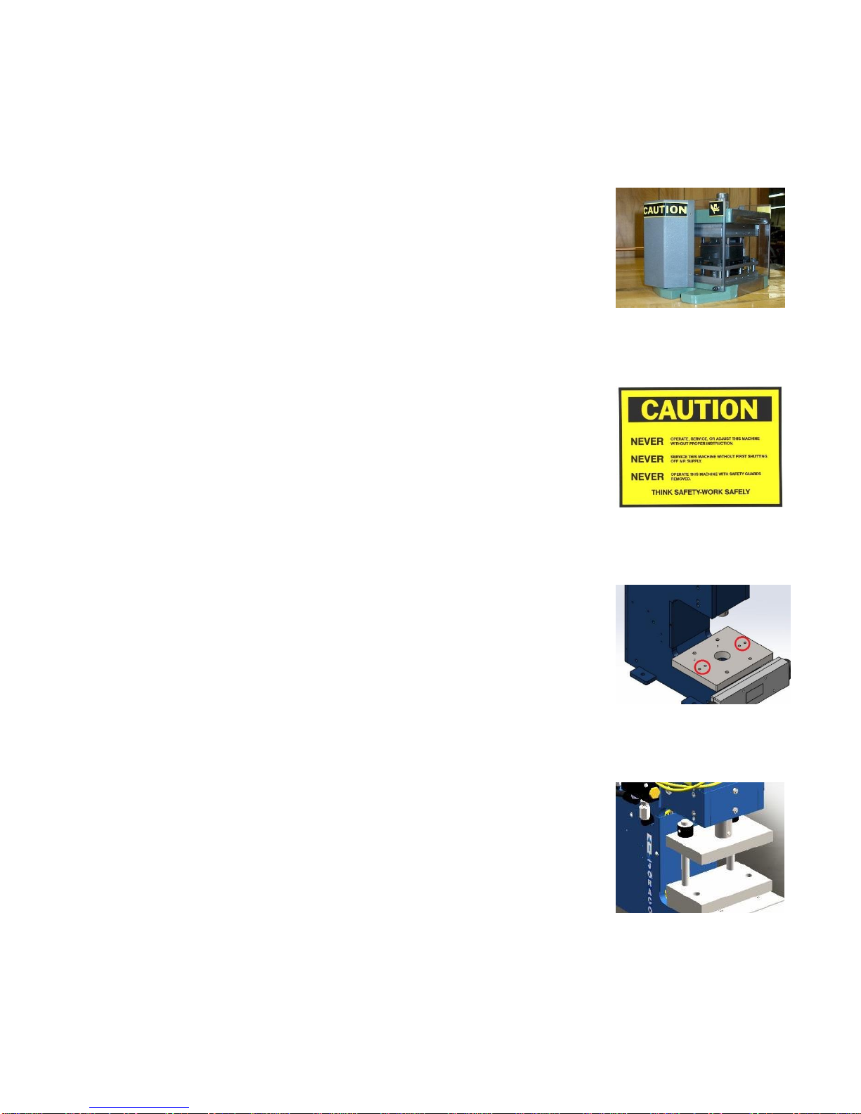
NOTE: Once tools have been set, always
replace all press guards before
proceeding.
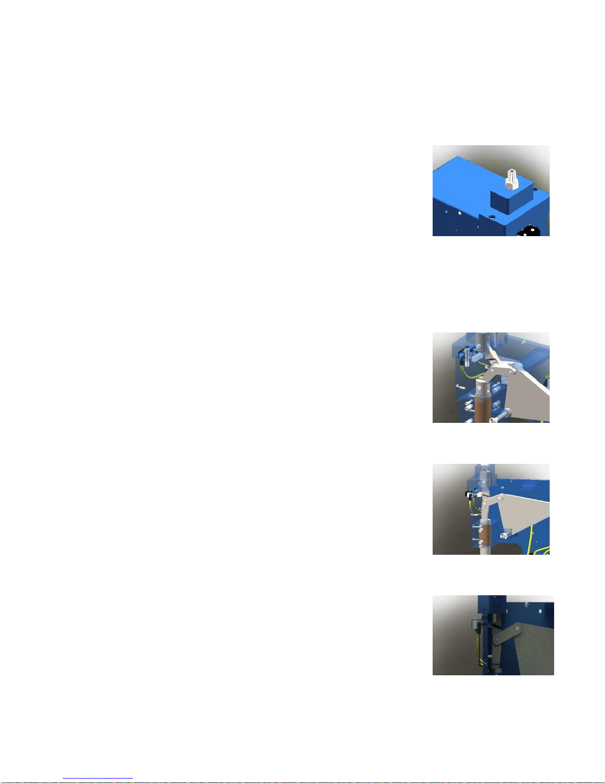
3. Important principles of set up and
operation.
(See photos 2.10, 2.11, 2.12)
When setting up and operating it is
important to keep in mind that the press is
a pneumatically powered TOGGLE press.
The key element in the machine is the
TOGGLE or KNUCKLE JOINT. A toggle is a
simple machine in and of itself. It is a great
multiplier of force. The press takes the
output of the cylinder, couples it to a lever,
which drives the toggle. As the toggle
straightens it drives the press ram
downward, creating a powerful squeeze at
the end of the stroke. The moment that the
toggle hits end of stroke, the upper toggle
link encounters a stop block. The press is
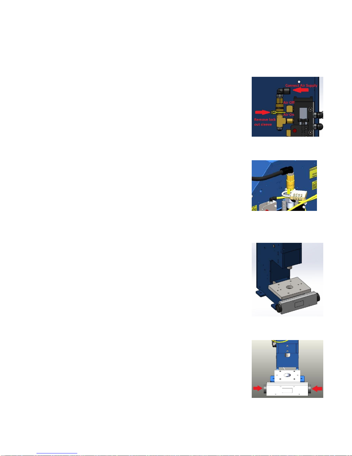
then reversed when the impulse pin is
driven out through the front plate, which in
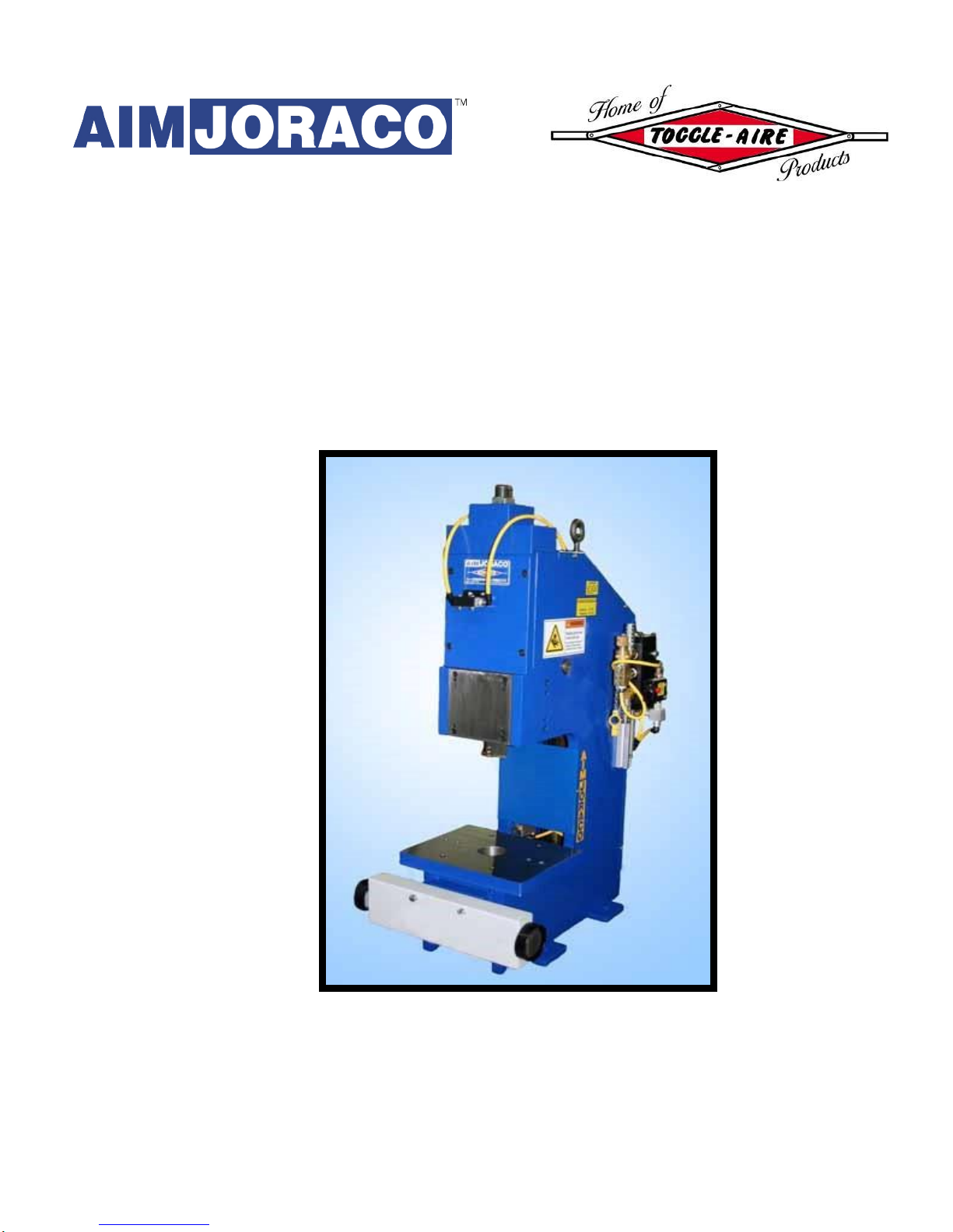
turn actuates the return valve (A-2530).
When controlled in this manner the press is
very accurate, with a repeatability of plus
or minus .001". It is crucial that you
recognize this relationship. Your tooling
should be built with a shut height that falls
within the shut height range of the press.
In standard 2530 presses this is approx.
5.375" maximum to 4.625" minimum and
in standard 3530 presses this is approx.
6.375” maximum to 5.625” minimum.
Photo 2.9
Photo 2.10
Photo 2.11
Photo 2.12

TOGGLE-AIRE MODEL 2530 & 3530 SERIES PRESSES
INSTALLATION, OPERATION, AND MAINTENANCE
-9-
(Important principles, continued)
Your tooling must be built to allow the
toggle to straighten out. If the tooling is too
high, or if you set the ram too deep, the
press will not be able to complete the
stroke and stall.
In BEM valve configuration if you stall the
press during set up, you can either shut off
the air supply and manually move the press
or, with air supply on, actuate the Optional
Aux. Ram Up Valve. (See photo 2.14). This
will send the ram back to the up position.
Re-adjust the depth setting so the toggle
can straighten.
Do not confuse the nature of the force
curve in the ram with the Ram Adjusting
Screw or depth adjustment. The ram force
developed by the press is not affected by
the Ram Adjusting Screw or where you are
set in terms of ram depth. The only thing
that affects ram force is the air pressure
used to power the press. The Ram
Adjusting Screw is simply an end of stroke
adjustment, much like the adjusting collar
found on full revolution, mechanical power
presses.
In fabrication jobs like punching, piercing,
and blanking enter the punch only as deep
as necessary to clear your blank, etc.
Always set up so that the press is doing the
work as close to the end of stroke as
possible, where the toggle is close to
straight and the rated strength of the press
is developed.
Finally, once the tools have been set and
locked in place, using the regulator on the
Filter, Regulator, Lubricator Unit, adjust
the air pressure to 5 to 10 PSI above the
minimum required to do the job. Any
additional line pressure is wasted, and
causes unneeded "wear and tear" on the
machine, etc.
Consult the factory if your application
requires shorter strokes, additional shut
height, etc.
Photo 2.13
Supplied with BEM control
systems only. Not req'd on CSR-G2
systems.
Photo 2.14

TOGGLE-AIRE MODEL 2530 & 3530 SERIES PRESSES
INSTALLATION, OPERATION, AND MAINTENANCE
-10-
Section III: Maintenance
1. LUBRICATION.
A. Press components.
(See photo 3.1, 3.2)
1. One Shot Lubrication Systems.
If your press is equipped with the
L-2-P One Shot Lube System (photo
3.2), fill the reservoir with 20 wt.
general purpose machine
lubricating oil. With the press ram
in the up position, pull the plunger
all the way up and release. The
pump will meter the oil to the
various points of lubrication. Upon
filling the reservoir for the first
time, it may take several pumps to
purge the system of air. Generally,
two pulls of the plunger per shift is
adequate.
B. Air Supply
(See Photo 3.3, 3.4)
1. Follow the instructions provided by
the manufacturer of the Filter,
Regulator, Lubricator Unit you are
using. (See Section I, Paragraph
5A). Fill the reservoir with Joraco
Air Tool Oil, Pt. No. JO-FRL. Adjust
the drip rate to approx. one drop
per 100 strokes of the press. Only
use oil specifically formulated for
use in pneumatic equipment.
2. GENERAL.
1. Regularly check the function of
the Synchro-Sig Actuator, Set Up,
and Aux. Ram Up Valves.
2. Regularly check all mechanical
aspects of the press including
fasteners, pivot pins and set
screws. Tighten any fasteners if
loose; replace any badly worn or
broken pins or links. Check linkage
bushings for wear and replace if
necessary.
Photo 3.1
Photo 3.2
Photo 3.3
Photo 3.4

TOGGLE-AIRE MODEL 2530 & 3530 SERIES PRESSES
INSTALLATION, OPERATION, AND MAINTENANCE
-11-
Section IV: Parts Identification Drawing
1. Linkage Parts (See pages 11 & 12) Model 2530 and Model 3530 Interchangeable.
2. Valving Parts (See pages 11 & 12) Model 2530 and Model 3530 Interchangeable.
FRONT RIGHT BACK

TOGGLE-AIRE MODEL 2530 & 3530 SERIES PRESSES
INSTALLATION, OPERATION, AND MAINTENANCE
-12-
Section V: Replacement Parts List
Linkage Parts:
JO-110 Lever, Standard Steel, 3530..................................................
JO-210 Cap .......................................................................................
JP-6 Cylinder Yoke........................................................................
JP-710 Ram Yoke..............................................................................
JP-810 Toggle Link, (set of 2)............................................................
JP-1010 Ram Adjusting Block .............................................................
JP-1110 Ram Adjusting Screw............................................................
JP-1210 Press Ram.............................................................................
JP-1310 Front Plate Assembly ...........................................................
JP-1416/39 Main Pivot Pin with Retaining Rings......................................
JP-27 Ram Screw............................................................................
JP-3310 Adjusting Screw Lock Nut......................................................
JP-35B Pivot Pin................................................................................
JP-35C Pivot Pin................................................................................
JP-3510A Pivot Pin................................................................................
JP-3510B Pivot Pin................................................................................
JP-3610 Pivot Pin................................................................................
BK-3500 Linkage Bearing Kit ...............................................................
Cylinder Parts:
3530MC/2530MC Main Cylinder, Complete...............................................
JP-4-3530/2530 Replacement Cylinder Tubes Std. Stroke (3 pcs.).........
JP-1/5-3530/2530 Piston Rod Assembly ....................................................
JP-26 Cylinder Screw w/ lock washer (set of 4).......................
JP-32 Cylinder Hold Down Screw (set of 2).............................
SK-3530/2530 Cylinder Seal Kit............................................................
Control Parts:
3530MVA Main Power Valve Assembly.................................................
A-2530 Return Valve..........................................................................
1026B Return Valve Bracket ............................................................
IP-2530 Return Valve Impulse Pin......................................................
B-2530 Set Up Valve Assembly.........................................................
C-2530 Shuttle Valve.........................................................................
D-2530 Quick Exhaust Valve .............................................................
CSR-G2M CSR-G2 Stroke Completion Module......................................
SK-D, Type II Quick Exhaust Seal Kit, New style valves .............................
E-2530 4-way Power Valve................................................................
F-2530 Aluminum Manifold................................................................
G-2530 On-Off Valve w/ Lock Out......................................................

TOGGLE-AIRE MODEL 2530 & 3530 SERIES PRESSES
INSTALLATION, OPERATION, AND MAINTENANCE
-13-
Section V: Replacement Parts List, Continued
Control Parts Cont:
KOS-2530 Key Operated Air Supply Shut Off..............................................
H-2530 Muffler, Adjustable......................................................................
I-2530 Muffler, Steel..............................................................................
J-2530 Auxiliary Ram Up Valve..............................................................
SS-PB Std. Two Hand Actuator w/ guard...............................................
SS-OT Optical Touch Two Hand Actuator w/ Power Supply..................
PS-SSOT Replacement Power Supply for SS-OT Actuator........................
PK-2530 Plumbing Kit (includes all tubing & fittings in std. control pkg.)...
Misc:
VC-2530 Replacement Valve Cover.....................................................
GK-2530 Rear Guard Kit (2 rear covers)..............................................
PC-2530 Pneumatic/Electronic Stroke Counter....................................
L-2-P-2530 One Shot Lube System Retrofit Kit........................................
L-2-P-2CC Pump Assembly Only, One Shot Lube System.....................
DT-2530 Bottom of Stroke Dwell Timer................................................
FRL-2530 Filter, Regulator, Lubricator Unit............................................
Tooling Components:
TL-4.6-Punch Toggle-Lock Punch each..............................................................
TL-4.6-Die Die Assembly each …………………………………………………..
RD-Post Hardened Alignment post each....................................................
Call for current prices and availability 1-888-889-4287

TOGGLE-AIRE MODEL 2530 & 3530 SERIES PRESSES
INSTALLATION, OPERATION, AND MAINTENANCE
-14-
Valving Schematic BEM (Impulse) Mode (Optional)
Valving Schematic CSR-G2 (Constant Signal Required) Mode (Standard)
Automated Industrial Machine, Inc

TOGGLE-AIRE MODEL 2530 & 3530 SERIES PRESSES
INSTALLATION, OPERATION, AND MAINTENANCE
-15-
Automated Industrial Machine, Inc

THINK SAFETY . . . WORK SAFELY . . .
Automated Industrial Machine, Inc. Joraco Div.
347 Farnum Pike, Smithfield, RI, USA, 02917 Phone 401-232-1710
About Control Systems . . .
Unless otherwise specified, your TOGGLE-AIRE
press has been shipped complete with all valving
necessary for two hand, single stroke operation,
including one of our SYNCHRO-SIG series two hand,
anti-tie down actuators. The actuators provide
"state of the art", anti-tie down control. The two
buttons (on the SS-PB series) or the two photo optic
"sensors" (on the SS-OT series) must be
simultaneously activated to provide a down signal
to the press. When one or both are released, the
down signal is terminated. Both buttons or
"sensors"
must be totally released before the units will allow
another down signal. The units cannot be locked or
tied down to allow single hand operation.
Standard presses are valved to operate in the
CSR-G2 mode. That is, the operator must give the
controller a constant signal for the ram to descend
to the bottom of
the stroke. If given a constant
signal, the ram will not reverse until it has reached
maximum strength and travel. However, the ram
will reverse at any point the signal is broken.
In some applications you may desire for the ram to
not reverse when the signal is broken. This is BEM
“impulse” Mode. Once the press has been
activated the ram will descend to the bottom of
stroke without requiring a constant signal.
Repeatability in this mode is plus or minus .001". If
purchased in this mode the press can be easily
converted to CSR-G2 mode by purchasing the CSR-
G2 Conversion Kit, Part No. CSR-G2-CON-1530.
Existing valving, including the SYNCHRO-SIG unit,
remains intact and is utilized. Conversion requires
approximately 15 minutes and is easily
accomplished.
Please contact our engineering department to
discuss any questions you may have about control
systems, modifications, and your applications. We
are glad to supply our presses built to your
specifications should you require other than our
standard systems.
Factory Support . . .
Our 40 year reputation for
providing quality TOGGLE-
AIRE presses that meet a wide
range of special
requirements
and our 60 years of service
and support experience are all
available to you with one
phone call. It's your biggest
advantage in dealing directly
with our
factory. Make use of
it. Please call with any and all
questions you may have
regarding your applications
and our equipment.
WARRANTY
AIM, Inc. (hereafter referred to as the
manufacturer) warrants that all TOGGLE-
AIRE products will be free from defects in
material and workmanship for a period of 180
days from the date of shipment to the original
purchaser. Any claim made against this
LIMITED WARRANTY must be made by
contacting the customer service department
of the manufacturer. At its option, AIM will
repair or replace any product it deems
defective under the terms of this warranty. If
factory service is required, transportation
costs to and from the factory are to be paid
by the purchaser. This warranty does not
apply to equipment that has been subject to
abuse, misapplication, negligence, improper
maintenance, alteration, or failure to follow
manufacturer's instructions.
AIM’s SOLE OBLIGATION UNDER THIS
WARRANTY IS STATED ABOVE. THIS
WARRANTY IS IN LIEU OF ALL OTHERS,
EXPRESSED OR IMPLIED, AND UNDER NO
CIRCUMSTANCES WILL JORACO,
INCORPORATED BE LIABLE FOR ANY
CONSEQUENTIAL DAMAGES RESULTING FROM
THE USE OF TOGGLE-AIRE PRODUCTS
This manual suits for next models
1
Table of contents
Other AIM Joraco Power Tools manuals
Popular Power Tools manuals by other brands

Avdel
Avdel 7536 instruction manual

Hougen-Ogura
Hougen-Ogura PUNCH PRO 76000PR Operator's manual

Drill Master
Drill Master 67042 Set up and operating instructions

Desoutter
Desoutter EPB 8-1800-10S Product instructions

Milwaukee
Milwaukee M18 FMT Original instructions

AME Intl.
AME Intl. 67125 Instruction manual & parts breakdown