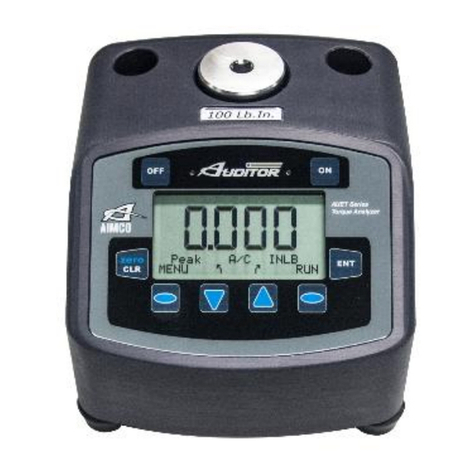
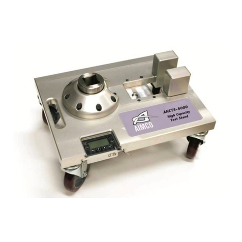
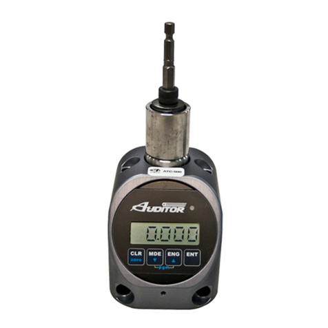
Aimco AUDITOR AUET User manual

AUET & AUET/MTM Desktop Torque
Testers
Quick Start Guide

2
See Product User Guide for:
•Safety Requirements
•Step By Step Functionality
•Detailed Operating Procedure
SCREEN AND BUTTON DIAGRAM
Figure 1
16
1. Data Display
2. Operating Mode
3. Menu Mode Status
4. Selection Arrow – Down
Change Operating Mode
Scroll Down through Menu screens
5. Left Selection Button
Menu Mode
Reduce Parameter Value
Select Parameter
6. NOK Value Indicator LED (RED)
7. Clear Data Display Value / Manually
ZERO Display
8. Power On
9. Power Off / Charging Mode
10. Enter
Set Values
Back up one Menu Screen
11. OK Rundown / Charging Mode
Indicator LED (GREEN)
12. Right Selection Button
Data Storage Mode
Increase Parameter Value
13. Selection Arrow – Up
Change Engineering Units
Scroll Up through Parameter
Screens
14. Data Storage Mode Status
15. Engineering Unit Status
16. All Clear Status Indicator (Absent
when A/C turned OFF)
17. Menu Screen Indicator / Stored
Rundown Number
18. Angle / Pulse Value Display
19. External Power Supply Indicator

3
BASIC FUNCTIONS
Turning On / Off
To turn the AUET & AUET/MTM on, press the “ON” button (Figure 1). The AIMCO logo will
be displayed for approximately 4 seconds, then the unit will start at the RUN or sequential
MEM mode of the tester.
To turn the AUET & AUET/MTM off, simply press the “OFF” button.
Set Torque Reading Mode
OPERATING MODE Descriptions
By selecting the proper Operating Mode, the user can properly take torque readings from a
variety of manual and powered tools.
•PEAK
This mode will provide a display of the maximum torque value achieved by the tool during
operation. This mode is used for all continuous drive tools impact or impulse tools, dial
wrenches and to identify highest torque delivered with click type wrenches.
•1st PEAK
This mode will detect and display the “first peak” achieved by click wrenches and cam-over
screwdrivers.
•PULSE
This mode counts the number of events (pulses or impact blows) in a cycle. This mode does
not change the manner in which peak torque is identified.
•TRACK
This mode will display torque in real-time as it is applied to the connected transducer. Track
mode is used primarily for calibration of the unit or identifying the condition of the transducer.
In Track Mode with no torque on the transducer, the display should show zero.
While in the Main Display screen, press the Selection Arrow-Down button to cycle through
the available Operating Mode choices. The choices will be displayed in the following order:
Setting ENGINEERING UNITS
The AUET & AUET/MTM must be in RUN MODE in order to change the Engineering Units.
If torque values have been stored in the AUET & AUET/MTM while in MEMORY MODE, then
the memory must be cleared in order to change the Engineering Units.
While in the Main Display screen, press the Selection Arrow-Up button to cycle through the
available Engineering Unit choices. The choices will be displayed in the following order:

4
Sign Lock
The SIGN LOCK feature allows the user to select the rotation direction in which a torque peak
will be captured. With SIGN LOCK set to ON, the initial first rundown direction is set as the
default direction.
If the initial rundown was performed in a clockwise direction a positive reading indicates a
reading taken in the clockwise direction while a negative torque value indicates a reading
taken in the counter-clockwise direction. If the initial rundown is taken in a counter clockwise
manner, then the opposite will hold true. Any readings taken in the non-selected direction will
be measured, but not captured / displayed as a peak value.
The direction of the first rundown taken after tester is powered ON will be the direction
measured. If initial rundown direction is NOT the direction to be measured, turn tester
OFF, restart and run in desired direction.
With SIGN LOCK turned OFF, peak values in both the clockwise and counter-clockwise
directions will be captured and displayed.
Since most torque rundowns are conducted and readings are taken in the clockwise direction,
the user may find it beneficial to turn this feature ON.
Turning Sign Lock ON / OFF
1. From the main display press MENU.
2. Press the Right Selection button to select PEAK OPTIONS MENU.
3. Use the Selection Arrow buttons to select SIGN LOCK.
4. Use the Left Selection button to toggle SIGN LOCK on or off.
5. When the desired value is selected, press ENTER to save and progress to the next MENU
level.
At any Menu level, pressing ENT twice will return to the Main Display Screen at the previously
set Operating Mode.
Charging the Auditor AUET & AUET/MTM Desktop Torque Tester
1. Plug the 100 – 240 VAC Charger into DC Power Supply port (Figure 3).
2. Plug the Charger into a 100–240 VAC power outlet using the appropriate plug end.
3. Press the “Off” button on the front panel (Figure 1).
4. The Charging Mode Indicator LED (Green, next to “ON” button) should begin to flash
green.
symbol will be displayed on the Main Display screen if the unit is turned on.
5. When the AUET & AUET/MTM is fully charged the LED will stop flashing.
6. The AUET & AUET/MTM can be used as normal in AC mode with the charger connected.
7. When used in DC mode (Battery) and the battery charge is low, the symbol (low
battery) will show on the Main Display screen, see Figure 1, (19). The 100–240VAC
Charger should be plugged into the unit immediately to continue uninterrupted operation.

5
Using the AUET & AUET/MTM in RUN MODE
RUN MODE can be used to quickly and
easily take torque readings using a variety of
tools in situations where storage of data and
statistical feedback is not necessary.
With the AUET & AUET/MTM turned ON,
observe the Data Storage Mode Status field
(Figure 1). If RUN is displayed, the AUET &
AUET/MTM is in RUN MODE and can then
be configured accordingly. If the status
reads MEM, then the AUET & AUET/MTM is
in MEMORY MODE.
Install the supplied driving bit into the Torque
applying device to be tested. Engage the
driving bit into the Hex screw in the supplied
joint kit and run the torque applying device
per its instructions. The Main Display Screen
will show the Torque value received by the
built in transducer.
Clearing a Torque Value / RUN MODE
When in RUN MODE, if Auto Clear is turned
on by selecting a time value, the display
screen will automatically convert back to a
zero value after the set amount of seconds.
Auto Clear clears the display and sends the
value out to the serial port automatically.
When in RUN MODE, if Auto Clear is turned
OFF, the operator must manually clear a
torque value from the display:
1. Set the Auto Clear function to OFF.
2. While in the Main Display screen,
conduct a rundown.
3. After observing the torque value for the
rundown, press CLEAR.
4. The Main Display will convert back to a
zero value and the torque value is sent
out to the serial port automatically
SETUP OF EXTERNAL TRANSDUCER – AUET/MTM ONLY
The AUET/MTM can be used with a variety
of external transducers, whether supplied by
AIMCO or another manufacturer. Because
manufacturers use a wide range of
transducer technologies and connector
types, verify that the transducer you plan to
use is capable of being connected to and
communicating with the AUET/MTM. For
assistance with this, please contact your
AIMCO Distributor or authorized AIMCO
Sales Representative.
AIMCO’s lines of Auditor™ industry-
standard transducers are manufactured with
the proper connector-style for easy use with
the AUET/MTM and will be used as the
example in all following instructions.
Two (2) optional cables are available from
AIMCO to connect Auditor™ brand
transducers to the AUET/MTM:
•Part # ATDBLIS Connects the ATDA to
any Auditor™ ABRT- or ARTIS
Torque/Angle series transducer
•Part # ATDBRIS Connects the ATDA to
any Auditor™ ARTIS Torque Only series
transducer
Contact your AIMCO Distributor or AIMCO
authorized Sales Representative for
information on ordering these cables.
Connecting a Transducer
Align the red dot on the transducer-cable
connector with the red dot on the
TRANSDUCER CABLE INPUT port (Figure
2) and firmly press the connector into the
port. Set rotary switch to external port.
Setting up the Transducer to be used
The Auditor™ AUET/MTM must be set to
recognize the transducer connected to the
instrument. Most transducers can be made
to allow the Auditor™ AUET/MTM to self-
recognize the transducer simply when a
connection is made. For assistance with this,
please contact your AIMCO Distributor or

6
authorized AIMCO Sales Representative for
a transducer upgrade quotation.
For the typical, Industry Standard (IS) type
of transducer, the setup procedure is as
follows:
1. Turn the AUET/MTM On.
2. Within 3 seconds of pressing the ON
button, press the LEFT SELECTION
BUTTON (Figure 1) for CAL
3. Press ENT to SELECT UNITS. If a
transducer has been previously setup,
the data for that previous setup will be
shown.
4. Units of measure for use in setting up
the transducer may be changed in this
screen by pressing the UP OR DOWN
SELECTION ARROW to scroll through
the available units. Pressing ENT will
select the displayed unit of measure for
use in setup and then display the
SELECT FULL SCALE screen.
5. To change the number displayed to
match the transducer being setup,
press the RIGHT SELECTION
BUTTON to EDIT the number.
6. The upper right corner of the screen will
display the digit number that use of the
UP or DOWN SELECTION ARROWS
will effect. The bottom left corner of the
screen shows the increment of
adjustment that each press of the UP or
DOWN SELECTION ARROWS
changes the digit by.
7. Once the number displayed on the
screen matches the transducer to be
used, press ENT to confirm the set
value.
8. The next screen will display “(+/-)
0.000” and the A-D counts. Press and
hold the RIGHT SELECTION BUTTON
to EDIT the mV/V rating of the
transducer being setup. System
defaults to 2.00000 which is standard
for all Auditor IS transducers. To insure
that the selection is correct a change
should be made even if the default of
2.00000mV/v is correct. Using the UP
and DOWN SELECTION ARROWS
adjust the reading up and down to then
display the desired value. Press ENT if
this value is correct for the transducer
being setup. It is important to be sure
that the sign (+/-) shown on the A-D
matches the direction of the Cal
mode. If in +Cal then the sign must
be positive. If in –Cal then the sign
must be -. Rotation of the transducer
shaft will facilitate a change from +
to – should that be necessary.
9. Percentage of Full Scale is the next
adjustment. Default is 100. To limit the
readable range of the transducer to be
used, use the RIGHT SELECTION
BUTTON and the UP or DOWN arrows
to change this value. Hit ENT once the
desired value is displayed.
10. Press the DOWN SELECTION
ARROW to set the –Cal. Confirm –Cal
by hitting ENT. Repeat steps 8 & 9.
11. After mV/V and Full Scale have been
entered, the display returns to the A-D
count screen. Hit ENT
12. If the value is correct, press ENT and
PGM will show on the screen.
13. Press the LEFT SELECTION BUTTON
to Save the setting. The unit will power
itself off and will hold the set value until
it is changed in the future or a different
Intellect transducer is attached to the
unit.


AIMCO CORPORATE HEADQUARTERS AIMCO CORPORATION DE MEXICO SA DE CV
10000 SE Pine Street Ave. Cristobal Colon 14529
Portland, Oregon 97216 Chihuahua, Chihuahua. 31125
Phone: (503) 254–6600 Mexico
Toll Free: 1-800-852-1368 Phone: (01-614) 380-1010
Fax: (01-614) 380-1019
LIT-MAN862 Rev. 07/2020
Printed in USA ©2020 AIMCO
Other manuals for AUDITOR AUET
1
This manual suits for next models
1
Table of contents
Other Aimco Test Equipment manuals
Popular Test Equipment manuals by other brands

Delta OHM
Delta OHM HD 2020 manual

pro master
pro master P180 manual

sugar-valley
sugar-valley RA09 Installation

Unit
Unit UTD1000 Series operating manual

AutoMeter
AutoMeter BVA-2100/RYD instruction manual

Kyoritsu Electrical Instruments Works, Ltd.
Kyoritsu Electrical Instruments Works, Ltd. KEW3551 instruction manual

Metrix
Metrix ScopiX IV Series user manual

B+K precision
B+K precision 1856D instruction manual

Tone
Tone TTC-60 instruction manual

GoVideo
GoVideo CCTV28 user manual

Kyoritsu Electrical Instruments Works, Ltd.
Kyoritsu Electrical Instruments Works, Ltd. KEW 5010 instruction manual

I-Tech
I-Tech IT5102 Series Programming guide