aion CHROMA User manual

CHROMA PARAMETRIC BOOST 1
PROJECT NAME
CHROMA
BASED ON
EFFECT TYPE
PROJECT SUMMARY
DOCUMENT VERSION
BOSS®SP-1 Spectrum
One of the rarest BOSS effects, a single-band swept-frequency EQ. Modified to boost the overall signal
level so it can be used as a boost pedal if desired.
Parametric equalizer / boost 1.0.0 (2021-10-22)
BUILD DIFFICULTY
Easy
Actual size is 2.3” x 1.86” (main board) and 2.3” x 0.86” (bypass board).
This project requires a dual 10kA/10kC potentiometer, which is not available from any of the
normal suppliers. It’s easy to make your own, but make sure to read the instructions on page 5
before undertaking the project.
IMPORTANT NOTE

CHROMA PARAMETRIC BOOST 2
TABLE OF CONTENTS
1Project Overview 8Drill Template
2Introduction & Usage 9Enclosure Layout
3-4 Parts List 10 Wiring Diagram
5-6 Build Notes 11 Licensing
7Schematic 11 Document Revisions
INTRODUCTION
The Chroma Parametric Boost is a clone of the BOSS®SP-1 Spectrum, one of the three original BOSS
compact stompboxes released in 1977. (The other two were the OD-1 OverDrive, which is available as
the Parhelion project, and the PH-1 Phaser.) It was discontinued in 1981, and due to its extreme rarity,
today it routinely sells for $500 or more on eBay.
The original SP-1 is a parametric equalizer with only two knobs. The frequency knob adjusts the boosted
frequency between 500Hz and 5 kHz, and the balance (or mix) knob adjusts the dry-to-wet signal ratio.
The gain and Q are fixed. Unlike some other parametric equalizers, it only boosts frequencies—it doesn’t
have the ability to cut. Its function is very similar to a fixed wah, and you can hear a wah-like effect if you
turn the Spectrum knob while a signal is being passed.
The updated version of the Chroma adds one new feature: the output volume has been increased and it
now includes a volume knob. This way, the output volume can be precisely trimmed for unity gain (which
is inexact in the original Spectrum depending on where the Balance control is set), or it can be used as
a booster with an adjustable frequency emphasis. When used in front of another overdrive pedal or to
overdrive an amplifier, you can get some really unique drive tones that wouldn’t otherwise be attainable.
USAGE
The Chroma has three controls:
• Spectrum sets the frequency of the boost.
• Balance pans between the dry signal and wet signal, acting as a sort of depth control.
• Volume sets the overall output of the effect. The original unit was fixed at unity gain and did not
have a volume control.

CHROMA PARAMETRIC BOOST 3
PARTS LIST
This parts list is also available in a spreadsheet format which can be imported directly into Mouser for
easy parts ordering. Mouser doesn’t carry all the parts—notably potentiometers—so the second tab lists
all the non-Mouser parts as well as sources for each.
View parts list spreadsheet →
PART VALUE TYPE NOTES
R1 1k Metal film resistor, 1/4W
R2 470k Metal film resistor, 1/4W
R3 10k Metal film resistor, 1/4W
R4 10k Metal film resistor, 1/4W
R5 1k Metal film resistor, 1/4W
R6 10k Metal film resistor, 1/4W
R7 18k Metal film resistor, 1/4W
R8 10k Metal film resistor, 1/4W
R9 22k Metal film resistor, 1/4W
R10 10k Metal film resistor, 1/4W
R11 10k Metal film resistor, 1/4W
R12 47k Metal film resistor, 1/4W Originally 10k. 47k increases the output going into the volume control
so it can be used as a boost. Increase the value even further to raise the
maximum volume.
R13 470R Metal film resistor, 1/4W
R14 33k Metal film resistor, 1/4W
R15 33k Metal film resistor, 1/4W
R16 100R Metal film resistor, 1/4W
RPD 2M2 Metal film resistor, 1/4W Input pulldown resistor.
LEDR 4k7 Metal film resistor, 1/4W LED current-limiting resistor. Adjust value to change LED brightness.
C1 47n Film capacitor, 7.2 x 2.5mm
C2 1uF Film capacitor, 7.2 x 3.5mm Original uses 4.7uF. There is space for the 4.7uF film capacitor, but 1uF
is sufficient.
C3 1uF Film capacitor, 7.2 x 3.5mm Original uses 4.7uF. There is space for the 4.7uF film capacitor, but 1uF
is sufficient.
C4 100n Film capacitor, 7.2 x 2.5mm
C5 3n3 Film capacitor, 7.2 x 2.5mm
C6 3n3 Film capacitor, 7.2 x 2.5mm
C7 1uF Film capacitor, 7.2 x 3.5mm
C8 1uF Film capacitor, 7.2 x 3.5mm Original uses 4.7uF. There is space for the 4.7uF film capacitor, but 1uF
is sufficient.
C9 47pF MLCC capacitor, NP0/C0G
C10 1uF Film capacitor, 7.2 x 3.5mm
C11 47uF Electrolytic capacitor, 5mm Reference voltage filter capacitor.

CHROMA PARAMETRIC BOOST 4
PARTS LIST, CONT.
PART VALUE TYPE NOTES
C12 100uF Electrolytic capacitor, 6.3mm Power supply filter capacitor.
C13 100n MLCC capacitor, X7R Power supply filter capacitor.
D1 1N5817 Schottky diode, DO-41
IC1 NJM3403AD Operational amplifier, DIP8
IC1-S DIP14 socket IC socket, DIP-14
GAIN 1k trimmer Trimmer, 10%, 1/4” See build notes (pg. 6) for notes on setting this trimmer.
BAL. 10kA/10kC 16mm right-angle PCB mount pot Must be made from a 10kA dual and 10kA single pot. See build notes for
how to do it.
SPECT. 100kB dual 16mm right-angle PCB mount pot
VOL. 100kA 16mm right-angle PCB mount pot
LED 5mm LED, 5mm, red diffused
IN 1/4" stereo 1/4" phone jack, closed frame Switchcraft 112BX or equivalent.
OUT 1/4" mono 1/4" phone jack, closed frame Switchcraft 111X or equivalent.
DC 2.1mm DC jack, 2.1mm panel mount Mouser 163-4302-E or equivalent.
BATT Battery snap 9V battery snap Optional. Use the soft plastic type—the hard-shell type will not fit.
FSW 3PDT Stomp switch, 3PDT
ENC 125B Enclosure, die-cast aluminum Can also use a Hammond 1590N1.

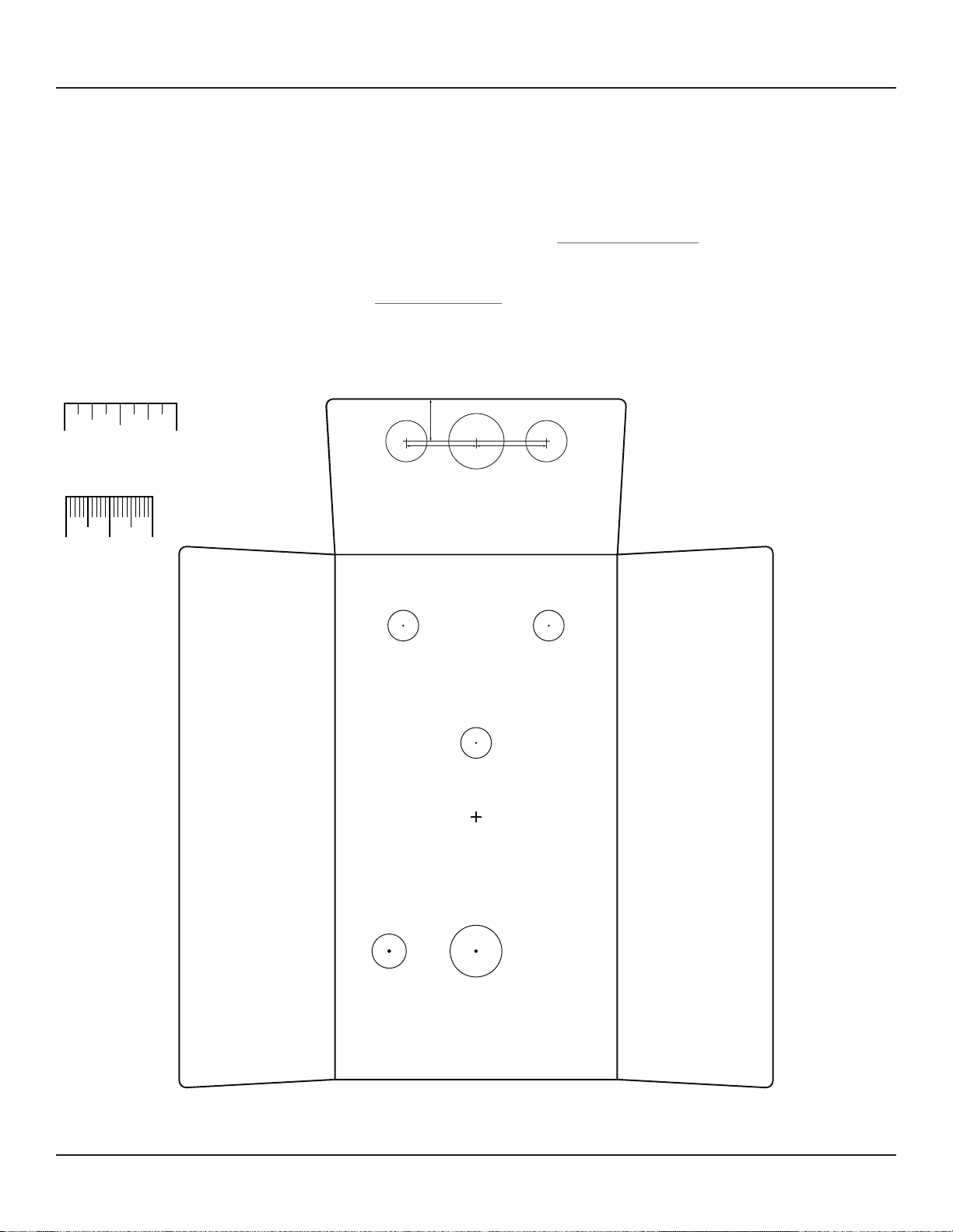
CHROMA PARAMETRIC BOOST 5
BUILD NOTES
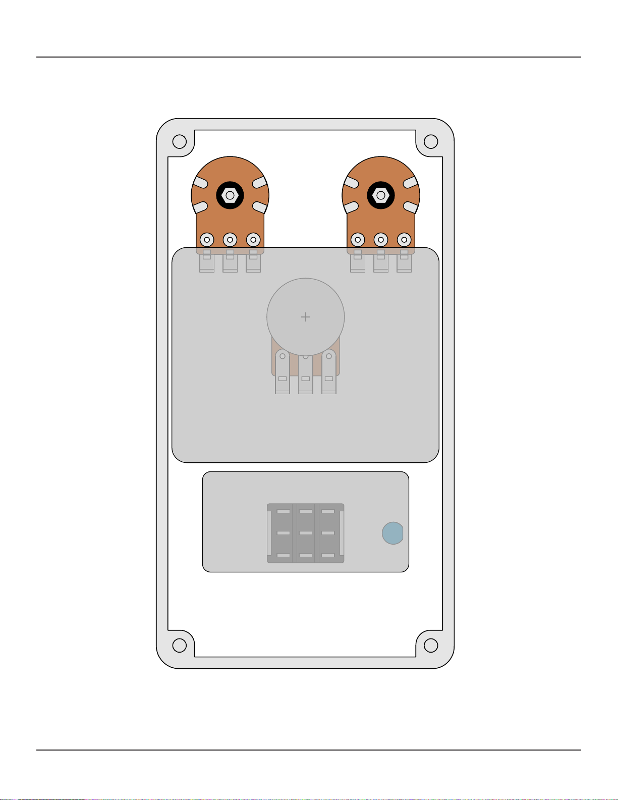
Making the dual 10kA/10kC “Balance” pot
The main reason the SP-1 has never been cloned before is due to the odd 10kA/10kC Balance pot.
This pot is unique to the pedal, and to custom-order it from Alpha would mean ordering at least 1,000
minimum. This has historically made the SP-1 prohibitive to DIYers wanting to build their own.
Fortunately, dual 10kA pots are available, and it’s very easy to switch out the top wafer of these pots
since the top wafer is identical in construction to the wafers used in single pots.
But, here’s the catch: since the top wafer is upside down, its taper is actually mirrored. The top wafer of
a dual 10kA pot is the same as a 10kC. Because of this, you will need to pull the replacement wafer from
a single 10kA pot, which will give you the correct “C” taper when used upside-down in a dual pot.
So for this, you will need one 10kA dual pot (preferably right-angle PCB mount) and one 10kA single pot
(preferably straight-pin PCB mount). It’s recommended to order at least two 10kA single pots in case
you break one while taking it apart.
Once you have the dual 10kA and single 10kA pots, follow these steps for making the dual pot.
1. Start with a 10kA dual pot (right
angle PCB mount) and a 10kA single
pot (straight-pin PCB mount).
4. On the single pot, break away
all the black plastic from the metal
shaft, taking care not to scratch
the carbon on the wafer itself. This
will take a fair amount of force.
You could also use a utility knife or
Dremel tool to cut it away.
2. On the dual pot, bend out the
four tabs with needle-nose pliers to
separate the top wafer.
5. Once the plastic has been broken
away, set aside the wafer and throw
the rest away. (Note that this photo
shows a solder-lug wafer, which
won’t fit the PCB without cutting
down the lugs. Use a straight-pin pot
as shown in step 1.)
3. On the single pot, bend out the
four tabs near the nut to separate
the metal cover from the rest.
6. Place the 10kA wafer on the dual
pot as shown, carbon side down, and
bend the four tabs inward to secure
it in place. Bend the pins straight
upward. This wafer will act as a
C-taper pot since it is upside-down.

CHROMA PARAMETRIC BOOST 6
BUILD NOTES, CONT.
Setting the gain trimmer
According to the SP-1 service manual, the Gain trimmer should be set as follows:
Test signal: 5KHz +/- 10% sine, -20dBm, set SPECTRUM, BALANCE at max (FCW), adjust trimmer
pot 1K for 2.5dBm output at peaking freq. (5KHz +/-10%)
Follow the process if you want, but it’s definitely overkill and an effect this simple does not need that
kind of precision. We couldn’t hear much difference across the whole sweep of the trimmer, but it would
be most noticeable at full clockwise (wet) on the Balance control. You might be able to make its impact
more pronounced by raising the value of R7.
IC selection
The original SP-1 used the Raytheon RC3403A “ground-sensing” quad op-amp. Raytheon hasn’t
manufactured analog components in several decades, and originals are scarce today—but fortunately
the New Japan Radio NJM3403A is an exact substitute and still in production.

SCHEMATIC
CHROMA PARAMETRIC BOOST 7
10kC
10kA
GND
2M2
1N5817
100uF
1kB
GND
100kA
+9V
100n
VA
100R
1k
47n
NJM3403A
NJM3403A NJM3403A
NJM3403A
470k
33k
33k
GND
47uF
GND
VB
VB
GND
VA
1uF
1k
VB
10k
10k
1uF
VB
10k
1uF
VB
VB
100n
10k
18k
3n3
VB
100kB
100kB
3n3
1uF
10k
22k
10k
VB
47k
47pF
470R
1uF
GND
IN
OUT
RPD
D1
C12
GAIN
1
2
3
VOLUME
1
2
3
C13
R16
R1
C1
2
3
1
IC1A
13
12
14
IC1D
6
5
7
IC1B
9
10
8
IC1C
411
R2
R14
R15
C11
C2
1
2
3
BALANCE A
1
2
3
BALANCE B
R5
R3
R4
C3
R10
C8
C4
R6
R7
C5
1
2
3
SPECTRUMA
SPECTRUMB
1
2
3
C6
C7
R8
R9
R11
R12
C9
R13
C10
GND

CHROMA PARAMETRIC BOOST 8
DRILL TEMPLATE
Cut out this drill template, fold the edges and tape it to the enclosure. Before drilling, it’s recommended
to first use a center punch for each of the holes to help guide the drill bit.
Ensure that this template is printed at 100% or “Actual Size”. You can double-check this by measuring
the scale on the printed page.
Top jack layout assumes the use of closed-frame jacks like the Switchcraft 111X. If you’d rather use
open-frame jacks, please refer to the Open-Frame Jack Drill Template for the top side.
LED hole drill size assumes the use of a 5mm LED bezel, available from several parts suppliers. Adjust
size accordingly if using something different, such as a 3mm bezel, a plastic bezel, or just a plain LED.
x: -0.65, y: +1.71 x: 0.65, y: +1.71
ø9/32” ø9/32”
x: 0, y: +0.66
ø9/32”
x: 0, y: -1.20
ø15/32”
x: -0.775, y: -1.20
ø5/16”
CENTER (0,0)
ø3/8” ø1/2”
0.385”
0.625” 0.625”
ø3/8”
OUT DC IN
125B
SPECTRUM
LEVEL
BALANCE
FOOTSWITCHLED
0 1 2
CM
0 1
INCH

CHROMA PARAMETRIC BOOST 9
ENCLOSURE LAYOUT
Enclosure is shown without jacks. See next page for jack layout and wiring.
125B

CHROMA PARAMETRIC BOOST 10
WIRING DIAGRAM
125B
IN +VGND N.C. N.C. OUT
PCB
IN
GND +V +V JACK GND JACK
OUTIN
GND GND PCB
OUT
Shown with optional 9V battery. If battery is omitted, both jacks can be mono rather than one being stereo.
Leave the far-right lug of the DC jack unconnected.

CHROMA PARAMETRIC BOOST 11
LICENSE & USAGE
No direct support is offered for these projects beyond the provided documentation. It’s assumed
that you have at least some experience building pedals before starting one of these. Replacements and
refunds cannotbe offered unless it can be shown that the circuit or documentation are in error.
All of these circuits have been tested in good faith in their base configurations. However, not all the
modifications or variations have necessarily been tested. These are offered only as suggestions based
on the experience and opinions of others.
Projects may be used for commercial endeavors in any quantity unless specifically noted. No
attribution is necessary, though a link back is always greatly appreciated. The only usage restrictions
are that (1) you cannot resell the PCB as part of a kit without prior arrangement, and (2) you cannot
“goop” the circuit, scratch off the screenprint, or otherwise obfuscate the circuit to disguise its source.
(In other words: you don’t have to go out of your way to advertise the fact that you use these PCBs, but
please don’t go out of your way to hide it. The guitar effects industry needs more transparency, not less!)
DOCUMENT REVISIONS
1.0.0 (2021-10-22)
Initial release.
Table of contents
Other aion Music Pedal manuals

aion
aion FRACTAL PARAMETRIC OVERDRIVE User manual

aion
aion CONSTELLATION User manual

aion
aion Arcturus User manual

aion
aion COMET User manual

aion
aion Lumitron User manual

aion
aion Lab Series User manual

aion
aion BETA PREAMP User manual

aion
aion TITAN User manual

aion
aion UBE SCREAMER User manual

aion
aion theseus User manual