aion Fusion User manual

FUSION DYNAMIC DISTORTION 1
PROJECT NAME
FUSION
BASED ON
EFFECT TYPE
PROJECT SUMMARY
DOCUMENT VERSION
Suhr®Riot™
A versatile distortion/overdrive noted for its Marshall-like “stack of amps” tone.
Distortion 1.0.0 (2023-03-24)
BUILD DIFFICULTY
Easy
Actual size is 2.3” x 1.86” (main board) and 1.78” x 0.87” (bypass board).

FUSION DYNAMIC DISTORTION 2
TABLE OF CONTENTS
1Project Overview 7Drill Template
2Introduction & Usage 8Enclosure Layout
3-4 Parts List 9Wiring Diagram
5Build Notes 10 Licensing
6Schematic 10 Document Revisions
INTRODUCTION
The Fusion Dynamic Distortion is an adaptation of the Suhr®Riot™ Distortion, originally released in
2009. The Riot is in the family of Marshall-like pedals and is lauded for its high gain “stack of amps” tone.
The Riot was developed as a modified clone of the MI Audio Crunch Box from 2006, which in turn was a
derivative of the Marshall Bluesbreaker along with some inspiration from the Fulltone® OCD®.
The updated version of the Fusion is very similar to the legacy PCB, but with the addition of an internal
slide switch so that 9V and 18V modes can both be used instead of being hardwired for one or the other.
As in the legacy project, we’ve also brought over the internal Presence trimmer from the Crunch Box.
The Riot never had one, though it had two fixed resistors that simulated a 20k trimmer set at around
1:00 (58% rotation). You can always set it to be exactly like the original, but by having the trimmer
available, you have access to an expanded range of tones not found in the original Riot.
USAGE
The Fusion has the typical controls of a 3-knob overdrive:
• Drive controls the amount of gain pushed into the hard-clipping diodes.
• Tone controls the treble response via a passive filter.
• Volume controls the overall output.
There is also one toggle switch, one internal trimmer and one internal slide switch:
• Clipping (toggle switch) selects between three different combinations of clipping diodes.
• Presence (trimmer) adjusts some of the fixed treble cut that comes after the tone control.
• Voltage (slide switch) selects between 9V and 18V power.

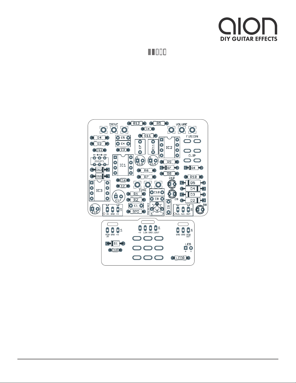
FUSION DYNAMIC DISTORTION 3
PARTS LIST
This parts list is also available in a spreadsheet format which can be imported directly into Mouser for
easy parts ordering. Mouser doesn’t carry all the parts—notably potentiometers—so the second tab lists
all the non-Mouser parts as well as sources for each.
View parts list spreadsheet →
PART VALUE TYPE NOTES
R1 1M Metal film resistor, 1/4W
R2 1k Metal film resistor, 1/4W
R3 1k Metal film resistor, 1/4W
R4 10k Metal film resistor, 1/4W
R5 1M Metal film resistor, 1/4W
R6 470R Metal film resistor, 1/4W
R7 470R Metal film resistor, 1/4W
R8 220R Metal film resistor, 1/4W
R9 100k Metal film resistor, 1/4W
R10 100R Metal film resistor, 1/4W
R11 22k Metal film resistor, 1/4W
R12 22k Metal film resistor, 1/4W
RPD 2M2 Metal film resistor, 1/4W Input pull-down resistor.
LEDR 10k Metal film resistor, 1/4W LED current-limiting resistor. Adjust value to change LED brightness.
C1 22n Film capacitor, 7.2 x 2.5mm
C2 33pF MLCC capacitor, NP0/C0G
C3 100pF MLCC capacitor, NP0/C0G
C4 220n Film capacitor, 7.2 x 2.5mm
C5 100n Film capacitor, 7.2 x 2.5mm
C6 100pF MLCC capacitor, NP0/C0G
C7 2.2uF Film capacitor, 7.2 x 5mm
C8 22n Film capacitor, 7.2 x 2.5mm
C9 22n Film capacitor, 7.2 x 2.5mm
C10 1uF Film capacitor, 7.2 x 3.5mm
C11 2.2uF Film capacitor, 7.2 x 5mm
C12 470n MLCC capacitor, X7R Power supply filter capacitor.
C13 10uF Electrolytic capacitor, 5mm Power supply filter capacitor.
C14 47uF Electrolytic capacitor, 5mm Reference voltage filter capacitor.
C15 10uF Electrolytic capacitor, 5mm Power supply filter capacitor.
C16 470n MLCC capacitor, X7R Power supply filter capacitor.
C17 100uF Electrolytic capacitor, 6.3mm Reference voltage filter capacitor.
C18 100n MLCC capacitor, X7R Power supply filter capacitor. Mistakenly labeled C19 on initial release.

FUSION DYNAMIC DISTORTION 4
PARTS LIST, CONT.
PART VALUE TYPE NOTES
D1 1N5817 Schottky diode, DO-41
D2 Ge Germanium diode, DO-7
Any germanium diode should work the same in this circuit, so use
whatever you can find. See build notes for precautions about polarity.
D3 Ge Germanium diode, DO-7
D4 Ge Germanium diode, DO-7
D5 Ge Germanium diode, DO-7
D6 1N914 Fast-switching diode, DO-35
D7 1N914 Fast-switching diode, DO-35
D8 3mm blue LED, 3mm, blue water-clear
D9 3mm red LED, 3mm, red diffused
D10 3mm red LED, 3mm, red diffused
D11 1N5817 Schottky diode, DO-41
D12 1N5817 Schottky diode, DO-41
IC1 JRC4580D Operational amplifier, DIP8
IC1-S DIP-8 socket IC socket, DIP-8
IC2 JRC4580D Operational amplifier, DIP8
IC2-S DIP-8 socket IC socket, DIP-8
IC3 TC1044SCPA Operational amplifier, DIP8 Can also use LT1054.
IC3-S DIP-8 socket IC socket, DIP-8
DRIVE 100kB 16mm right-angle PCB mount pot
TONE 10kC 16mm right-angle PCB mount pot
VOL. 10kA 16mm right-angle PCB mount pot
CLIP DPDT on-on-on Toggle switch, DPDT on-on-on See build notes for correct switch configuration.
VOLT. DPDT slide DPDT slide, micro E-Switch EG1271
LED 5mm LED, 5mm, red diffused
IN 1/4" stereo 1/4" phone jack, closed frame Switchcraft 112BX or equivalent.
OUT 1/4" mono 1/4" phone jack, closed frame Switchcraft 111X or equivalent.
DC 2.1mm DC jack, 2.1mm panel mount Mouser 163-4302-E or equivalent.
FSW 3PDT Stomp switch, 3PDT
BATT. 9V 9V battery snap Soft vinyl type. The hard-shell type will not fit.
ENC 125B Enclosure, die-cast aluminum Can also use a Hammond 1590N1.

FUSION DYNAMIC DISTORTION 5
BUILD NOTES
Clipping switch
The clipping switch is a DPDT on-on-on toggle. For this type of switch, depending on the manufacturer,
there are two different types of configurations for the center position, which are as follows:
The Fusion requires the Type 2 configuration, which is used by most major manufacturers such as
Taiway. If you’re considering a different brand, make sure to check the configuration of the center
position. Many of the on-on-on switches sold by Tayda or Love My Switches are Type 1 and will not work.
In addition, make sure you’re using an on-on-on switch and not an on-off-on switch, which has the same
appearance and also has 3 positions, but will not work in this circuit.
Germanium diodes
The Riot uses four germanium diodes as part of the clipping combinations. These days, the Russian D9
series are probably the most readily-available NOS germaniums, and will sound great in this circuit. But
be aware that these Russian diodes have the stripe on the anode rather than the cathode, meaning they
should be inserted backwards according to the PCB silkscreen.
This isn’t an issue for circuits like the Klon or Distortion+ that just use two germanium diodes, since it’s
electronically identical whether they’re both the right way or both backwards. However, since these are
in series with other diodes, if the germaniums are reversed in relation to the other diodes then the path
to ground will be blocked and only half the waveform will be clipped.
C19 capacitor
The initial run of Fusion PCBs had the capacitor on the footswitch PCB labeled C19 instead of C18. This
will be fixed in subsequent orders, but for now, just know that the MLCC capacitor on the footswitch
PCB should be 100n (0.1uF).
TYPE 1 TYPE 2

SCHEMATIC
FUSION DYNAMIC DISTORTION 6
Ge
GND
2M2
1N5817
100uF
GND
+9V
100n
100kB
10kA
1k
10k
1M
470R
1M
22n
100pF
220n
GND
100n
100pF
GND
1k
33pF
GND
10kC
22n
GND
20k TRIM
22n
GND
1uF
JRC4580
JRC4580
100k
100R
470R
220R
GND
VA
TC1044SCPA
GND
1N5817 1N5817
10uF
470n
GND
470n
GND
22k
10uF
22k
GND
47uF
GND
GND
VB
VB
VB
VB
VA
GND
VA
GND
2.2uF
2.2uF
JRC4580
JRC4580
IN
OUT
RPD
D1
C17
C18
DRIVE
1
2
3
VOLUME
1
2
3
R3
R4
R5
R6
R1
C1
C3
C4
C5
C6
D9
D10
D3D2
R2
C2
TONE
1
2
3
C8
PRESENCE
1
2
3
C9
D4D5
C10
2
3
1
IC2A
6
5
7
IC1B
R9
R10
R7
D7D6
R8
D8
A2
A3
A1
CLIP A
B2
B3
B1
CLIP B
1
2
3
4 5
6
7
8
IC3 D11 D12
C15
C16
C12
R11
C13
R12
C14
VOLTAGE
2
3
1
84
C7
C11
2
3
1
IC1A
6
5
7
IC2B
84
GND

FUSION DYNAMIC DISTORTION 7
DRILL TEMPLATE
Cut out this drill template, fold the edges and tape it to the enclosure. Before drilling, it’s recommended
to first use a center punch for each of the holes to help guide the drill bit.
Ensure that this template is printed at 100% or “Actual Size”. You can double-check this by measuring
the scale on the printed page.
Top jack layout assumes the use of closed-frame jacks like the Switchcraft 111X. If you’d rather use
open-frame jacks, please refer to the Open-Frame Jack Drill Template for the top side.
LED hole drill size assumes the use of a 5mm LED bezel, available from several parts suppliers. Adjust
size accordingly if using something different, such as a 3mm bezel, a plastic bezel, or just a plain LED.
x: -0.65, y: +1.71 x: 0.65, y: +1.71
ø9/32” ø9/32”
x: -0.85, y: +0.66
ø1/4”
x: 0, y: +0.66
ø9/32”
x: 0, y: -1.20
ø15/32”
x: -0.775, y: -1.20
ø5/16”
CENTER (0,0)
ø3/8” ø1/2”
0.385”
0.625” 0.625”
ø3/8”
OUT DC IN
125B
VOLUME
CLIPPING TONE
DRIVE
FOOTSWITCHLED
0 1 2
CM
0 1
INCH

FUSION DYNAMIC DISTORTION 8
ENCLOSURE LAYOUT
Enclosure is shown without jacks. See next page for jack layout and wiring.
125B

FUSION DYNAMIC DISTORTION 9
WIRING DIAGRAM
125B
IN +VGND N.C. N.C. OUT
PCB
IN
GND +V +V JACK GND JACK
OUTIN
GND GND PCB
OUT

FUSION DYNAMIC DISTORTION 10
LICENSE & USAGE
No direct support is offered for these projects beyond the provided documentation. It’s assumed
that you have at least some experience building pedals before starting one of these. Replacements and
refunds cannotbe offered unless it can be shown that the circuit or documentation are in error.
All of these circuits have been tested in good faith in their base configurations. However, not all the
modifications or variations have necessarily been tested. These are offered only as suggestions based
on the experience and opinions of others.
Projects may be used for commercial endeavors in any quantity unless specifically noted. No
attribution is necessary, though a link back is always greatly appreciated. The only usage restrictions
are that (1) you cannot resell the PCB as part of a kit without prior arrangement, and (2) you cannot
“goop” the circuit, scratch off the screenprint, or otherwise obfuscate the circuit to disguise its source.
(In other words: you don’t have to go out of your way to advertise the fact that you use these PCBs, but
please don’t go out of your way to hide it. The guitar effects industry needs more transparency, not less!)
DOCUMENT REVISIONS
1.0.0 (2023-03-24)
Initial release.
Table of contents
Other aion Music Pedal manuals

aion
aion NYSIAD Silicon Fuzz User manual

aion
aion COMET User manual

aion
aion PROCYON User manual

aion
aion CRESCENT AMP DISTORTION User manual

aion
aion ANDROMEDA User manual

aion
aion SOMNUS User manual

aion
aion Particle User manual

aion
aion CHROMA User manual

aion
aion TITAN User manual

aion
aion IBEX User manual

aion
aion PLASMA VINTAGE DRIVE User manual

aion
aion TORUS User manual

aion
aion Obscura User manual

aion
aion Lab Series User manual

aion
aion Onyx User manual

aion
aion Gladiator Dual Drive User manual

aion
aion ZIRCON SILICON FUZZ User manual

aion
aion AZURE User manual

aion
aion DYNAMO User manual

aion
aion TRITON MK. III User manual