Customer : CSN
Type : A318/A319/A320/A321
Rev. Date : May 01, 2018
Manual : AMM
Selected applicability : 0053-0053
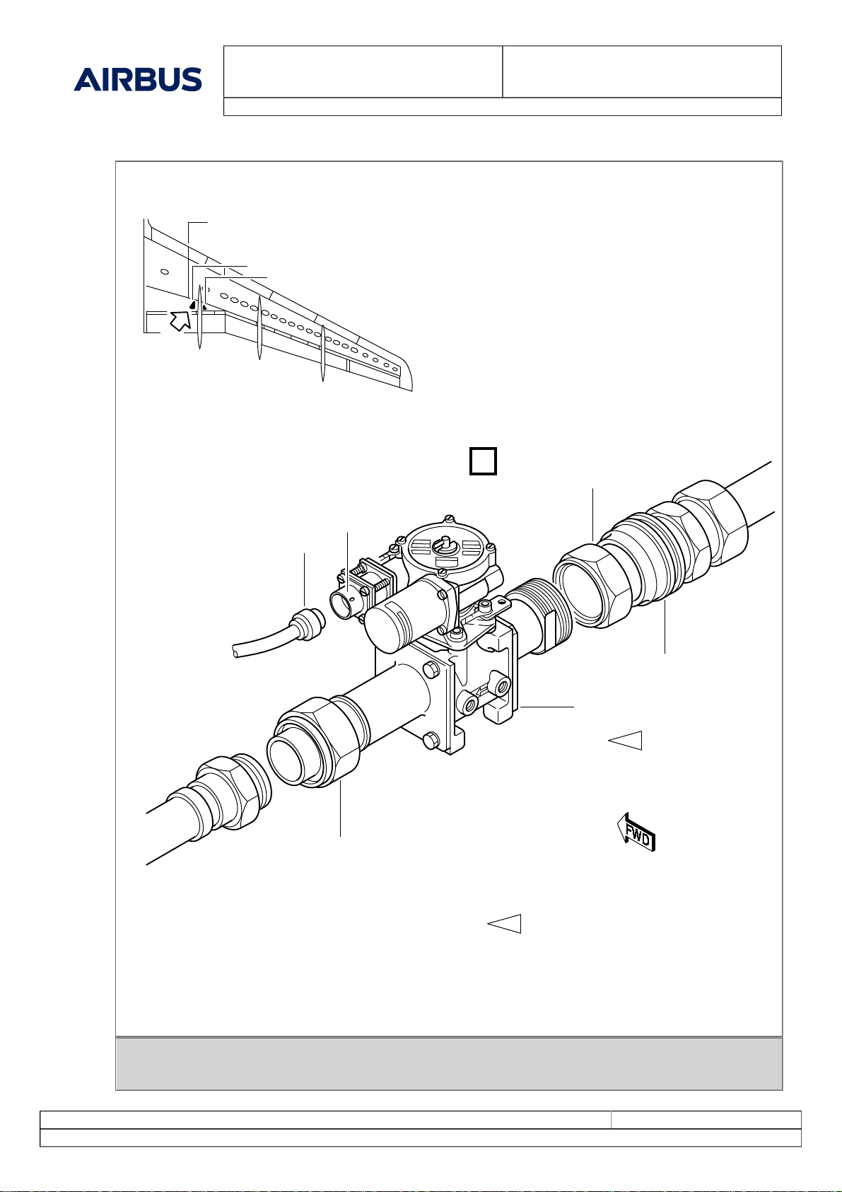
29-11-52-000-001-A - Removal of the Engine Pump Fire-Valve
Print Date: August 16, 2018 Page 5 of 6
© AIRBUS S.A.S. ALL RIGHTS RESERVED. CONFIDENTIAL AND PROPRIETARY DOCUMENT.
3. Job Set-up
** ON A/C 0001-0004, 0007-0099, 0101-0107, 0109-0115, 0126-0199, 0204-0204, 0207-0207, 0209-0249, 0251-
0299, 0301-0399, 0401-0449, 0451-0470, 0501-0549, 0551-0559, 0601-0650, 0701-0749
(Ref. Fig. Engine Pump Fire-Valve (1046GK))
** ON A/C ALL
Subtask 29-11-52-941-050-A
A. Safety Precautions
WARNING: OBEY THE HYDRAULIC SAFETY PROCEDURES.
(1) You must obey the hydraulic safety procedures (Ref. AMM TASK 29-00-00-910-002) when you do
work on the hydraulic system.
(2) As necessary, use the applicable SAFETY BARRIERS, specified by the operator's instructions and
your local regulations.
(3) Put a WARNING NOTICE(S) in position to tell persons not to pressurize the Green hydraulic system.
Subtask 29-11-52-864-050-A
B. Depressurize the Applicable Hydraulic System
WARNING: MAKE SURE THAT THE TRAVEL RANGES OF THE FLIGHT CONTROL SURFACES
ARE CLEAR BEFORE YOU PRESSURIZE/DEPRESSURIZE A HYDRAULIC SYSTEM.
(1) Depressurize the Green Hydraulic system (Ref. AMM TASK 29-00-00-864-001) .
(2) Depressurize the Green Hydraulic system reservoir (Ref. AMM TASK 29-14-00-614-001) .
Subtask 29-11-52-865-050-A
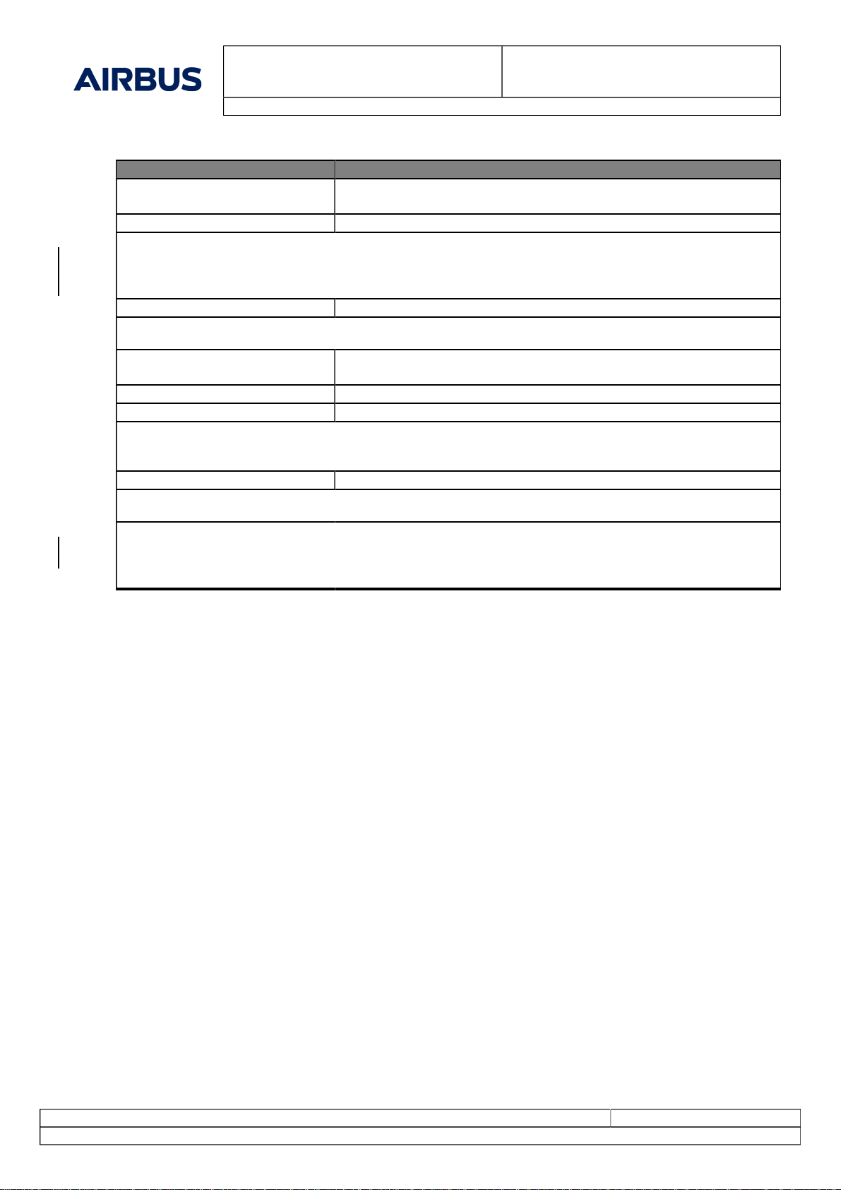
C. Open, safety and tag this(these) circuit breaker(s):
PANEL DESIGNATION FIN LOCATION
49VU HYD/FIRE VALVE/G/ENG1 1703GK C13
121VU HYDRAULIC/G HYD/PUMP ENG1/
MONG 1702GK R34
** ON A/C 0051-0099, 0101-0107, 0109-0115, 0126-0199, 0204-0204, 0207-0207, 0209-0249, 0251-0299, 0301-
0399, 0401-0449, 0451-0499, 0501-0549, 0551-0599, 0601-0749, 0751-0799, 0801-0830, 0832-0899, 0901-0999,
1001-1050, 1053-1151, 1153-1153, 1155-1200
Subtask 29-11-52-010-050-B
D. Get Access
(1) Put the ACCESS PLATFORM 3M (10 FT) below zone 574.
(2) Remove the access panels 574AB, 574BB.
(3) Put clean Textile-Lint free Cotton - (Material No. 14SBA1) below the engine pump fire valve (5).
(4) Put a CONTAINER 1 L (1/4 USGAL) below the access door opening, to collect the hydraulic fluid.
** ON A/C ALL
4. Procedure