Customer : CSN
Type : A318/A319/A320/A321
Rev. Date : May 01, 2018
Manual : AMM
Selected applicability : 0059-0059
29-13-47 PB 401 CONF 00 - SLIDE - COMPENSATED - REMOVAL/INSTALLATION
Print Date: June 08, 2018 Page 8 of 9
© AIRBUS S.A.S. ALL RIGHTS RESERVED. CONFIDENTIAL AND PROPRIETARY DOCUMENT.
WARNING: MAKE SURE THAT THE TRAVEL RANGES OF THE FLIGHT CONTROL SURFACES
ARE CLEAR BEFORE YOU PRESSURIZE/DEPRESSURIZE A HYDRAULIC SYSTEM.
WARNING: MAKE SURE THAT THE CONTROLS AGREE WITH THE POSITION OF THE ITEMS
THEY OPERATE BEFORE YOU PRESSURIZE A HYDRAULIC SYSTEM. UNWANTED
MOVEMENT OF HYDRAULICALLY OPERATED ITEMS CAN CAUSE SERIOUS INJURY
AND/OR DAMAGE.
(1) Pressurize the Yellow hydraulic reservoir (Ref. AMM TASK 29-14-00-614-002) .
(2) Fill the Yellow system reservoir (Ref. AMM TASK 12-12-29-611-001) or (Ref. AMM TASK 12-12-29-
611-002) .
(3) Pressurize the Yellow hydraulic system (Ref. AMM TASK 29-10-00-863-002) or
(Ref. AMM TASK 29-24-00-863-001) .
Subtask 29-13-47-790-050-A
E. Leak Test
(1) Examine the hydraulic connections of the compensated slide (1) for leaks.
Subtask 29-13-47-864-051-A
F. Depressurize the Applicable Hydraulic System
(1) Depressurize the Yellow Hydraulic system (Ref. AMM TASK 29-00-00-864-001) .
5. Close-up
** ON A/C 0001-0004, 0007-0099, 0101-0107, 0109-0115, 0126-0199, 0204-0204, 0207-0207, 0209-0249, 0251-
0299, 0301-0399, 0401-0449, 0451-0470, 0501-0549, 0551-0559, 0601-0650, 0701-0749
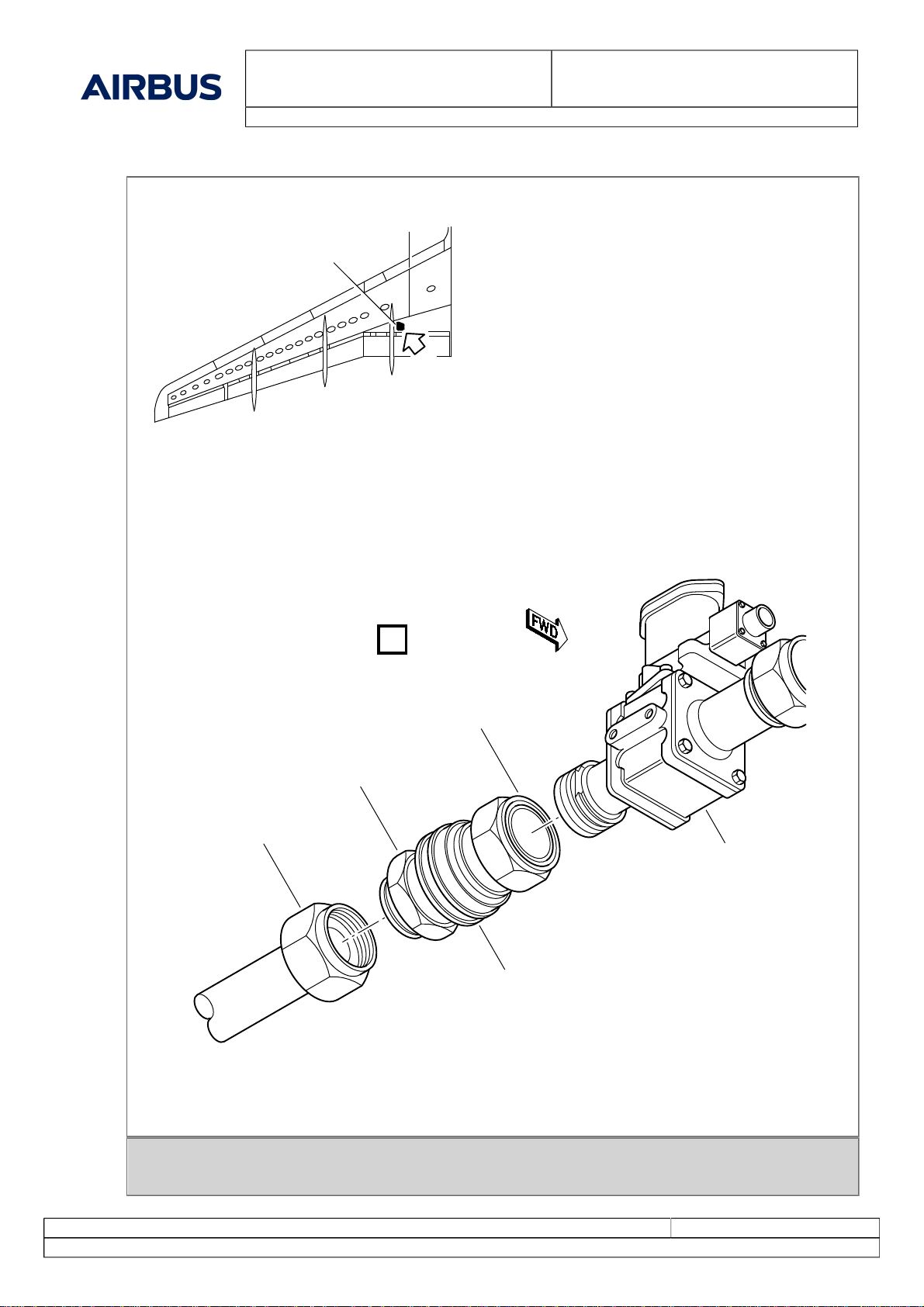
(Ref. Fig. Compensated Slide SHEET 1)
** ON A/C 0051-0099, 0101-0107, 0109-0115, 0126-0199, 0204-0204, 0207-0207, 0209-0249, 0251-0299, 0301-
0399, 0401-0449, 0451-0499, 0501-0549, 0551-0599, 0601-0749, 0751-0799, 0801-0830, 0832-0899, 0901-0999,
1001-1050, 1053-1151, 1153-1153, 1155-1200
Subtask 29-13-47-410-050-B
A. Close Access
(1) Make sure that the work area is clean and clear of tools and other items.
(2) Remove the CONTAINER 5 L (1.32 USGAL) from below the compensated slide (1).
(3) Install the access panel 674AB.
** ON A/C ALL
Subtask 29-13-47-942-051-A
B. Removal of Equipment
(1) Remove the SAFETY BARRIER(S)S.
(2) Remove the warning notice(s).
(3) Remove the access platform(s).
(4) Remove the ground support and maintenance equipment, the special and standard tools and all other
items.
** ON A/C 0001-0004, 0007-0099, 0101-0107, 0109-0115, 0126-0199, 0204-0204, 0207-0207, 0209-0249, 0251-
0299, 0301-0399, 0401-0449, 0451-0470, 0501-0549, 0551-0559, 0601-0650, 0701-0749
Figure 29-13-47-991-00100-00-A / SHEET 1/1 - Compensated Slide